

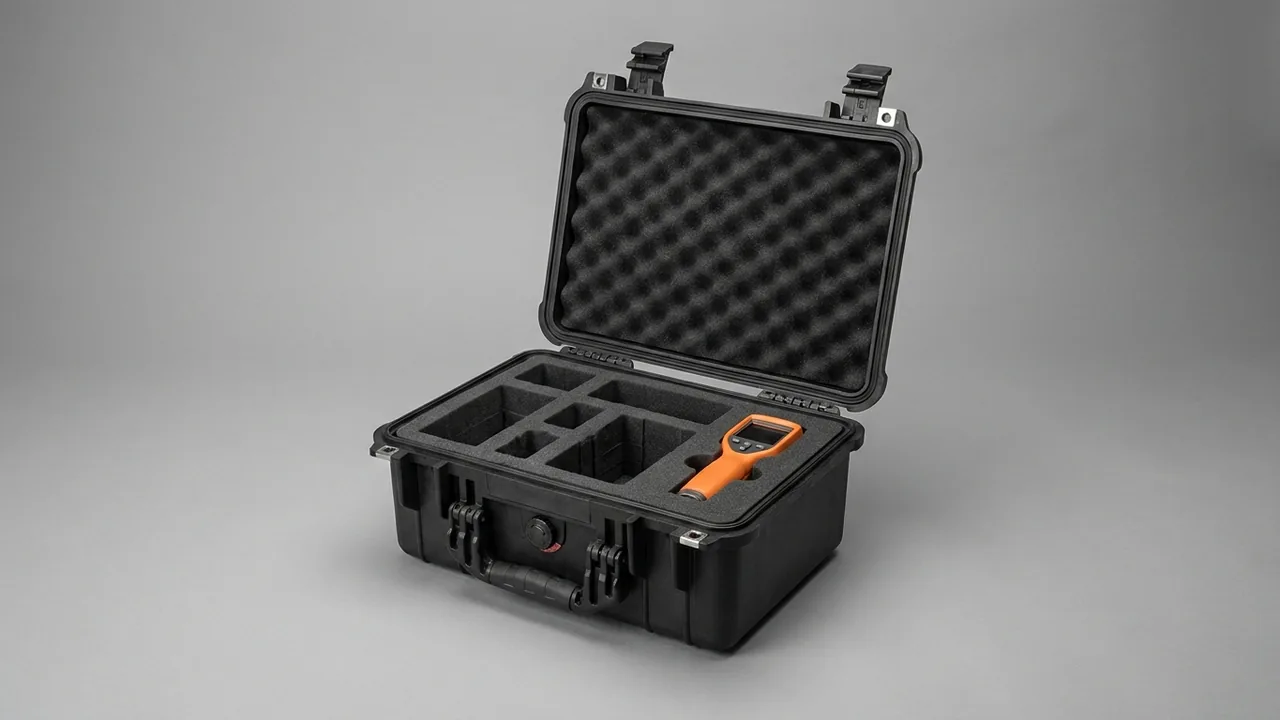
A fire pump set is normally shipped as seven families of hardware: pump body, impeller, mechanical seal, coupling, controller module, pressure transmitter and valves. Delivery distances range from a few hundred kilometres within one province to intercontinental sea freight. The key conclusion up front: protecting fire pump components in transit is not about making the case wall thicker. It is about satisfying four conditions at the same time, namely cleanliness of the mechanical seal mating faces, dimensional hold of the impeller and casing passages, moisture control around the controller module, and a case that delivers both IP67 sealing and a declared IK impact resistance, so that the set can be energised and pressure-tested on arrival. A fire pump is a standby-reliability asset: once a sprinkler head or hydrant opens, the pump must reach rated pressure within seconds. Micro-scratches, condensation and assembly misalignment introduced during transport tend to cause first-start failures far more often than normal running wear does. This article works through each component family, giving protection parameters, the standards behind them, and a method for case selection, for fire protection contractors and pump manufacturers.
Most projects still ship pump sets in timber crates filled with loose foam chips. Four problems recur on arrival. Mechanical seal faces are scratched by debris and begin weeping after a few dozen running hours. Impeller wear rings and casing passages pick up burrs during drops or stacking, producing vibration and a flow shortfall. Controller modules absorb moisture, insulation resistance falls, and commissioning triggers nuisance faults. Pressure transmitter and valve threads corrode, forcing site re-tapping. Less obvious is that metal swarf and dust inside the case are carried into the seal chamber when the case is opened, so the set has to be stripped and cleaned before assembly, which pushes the schedule out. These failure modes overlap with those described for general pump and valve component transit cases, but fire pumps carry one extra hard constraint: they must arrive in a maintenance-free standby condition.
Contents
- Fire pump set components and their transport damage map
- Impellers and casing passages: dimensional hold and impact avoidance
- Mechanical seals and shaft seals: cleanliness of the mating faces comes first
- Couplings and concentricity: constraining movement in transit
- Controller modules and pressure transmitters: moisture and vibration control
- Valves, flanges and pipe fittings: rust prevention and interface protection
- What IP67 actually means: IEC 60529 and GB/T 4208
- How the IK impact rating maps to case structural strength
- Blocking salt fog and high humidity on sea freight
- The emergency spares case: designed for install-on-arrival
- Insert material selection: EVA, PE, PU and antistatic options
- Transport validation: ISTA, GB/T 4857, ASTM D4169 and MIL-STD-810H
- Packing, marking and handover procedure
- Frequently asked questions
- Conclusion and further reading
Fire pump set components and their transport damage map
A fire pump package is usually split into six functional groups when it leaves the factory: hydraulic parts, sealing parts, drive parts, control parts, monitoring parts and piping parts. Their sensitivity to the transport environment varies enormously, and putting everything into one large crate separated only by a layer of bubble film is the single most common cause of high return rates. The table below lists the main weak points per component family together with a recommended zoning strategy, and it can serve as the first check layer of any packing list.
| Component | Main transport weak point | Recommended zoning |
|---|---|---|
| --- | --- | --- |
| Pump body and casing | Chipped flange faces, burred passages, coating damage | Dedicated heavy-duty zone, blind flanges fitted |
| Impeller | Deformed wear ring, chipped blade edges, lost balance | Individual cavity with axial and radial restraint |
| Mechanical seal | Scratched faces, displaced spring, twisted O-ring | Original inner pack plus secondary shock cavity |
| Coupling | Aged elastomer, damaged keyway, lost alignment mark | Compartmentalised, never in the same cavity as heavy parts |
| Controller module | Moisture ingress, board resonance, loosened terminals | Antistatic bag, desiccant, vibration-damping pads |
| Pressure transmitter | Deformed diaphragm, pulled leads | Soft-lined individual cavity, leads coiled and tied |
| Valves and fittings | Corroded threads, chipped sealing faces, broken handles | Split by bore size, dust caps on all ports |
Looking at the damage mechanics, transport failures rarely come from a single large shock. They come from sustained static load during long stacking, from low-frequency vibration in the 3 Hz to 30 Hz band inside the vehicle, and from condensation driven by day-night temperature swings. When those three loads combine, the first items to fail are usually the seal faces and the electrical modules, not the heaviest-looking casing. Selection work should therefore weight cushioning and moisture control as heavily as load capacity, rather than choosing a case purely by weight.
There is another frequent misjudgement in practice: treating fire pump components as ordinary industrial pump components. The difference is that a fire pump often sits in storage for months, sometimes over a year, before it is connected to the network, and that storage may be a temporary site warehouse with high temperature and humidity. Long storage combined with residual transport vibration accelerates rubber ageing and promotes pitting in plated surfaces. If the case has a seal that can be opened and closed repeatedly, and if the desiccant is designed as a replaceable element, the same case covers both the transport phase and the storage phase. That is why this article keeps returning to case structure rather than one-way packaging.
Impellers and casing passages: dimensional hold and impact avoidance
The impeller is the most balance-sensitive single part in a fire pump. On a cast impeller the wear ring clearance is typically in the 0.2 mm to 0.5 mm range, and once the ring goes oval or a blade edge rolls over, the installed pump shows reduced flow and shaft vibration, sometimes tripping a bearing temperature alarm. The protection objective is simple to state: the impeller must not move, must not carry load, and must not touch a hard surface.
The method has three steps. First, each impeller needs its own cavity; two impellers must never be stacked hub face to hub face, because pressure marks on the hub affect the fit on the shaft. Second, restraint combines an axial stop with a radial cradle: 20 mm to 30 mm thick EVA or PU blocks bear on both ends of the hub, while a curved saddle matched to the disc outside diameter grips the rim. Third, the spaces between blades are left unfilled, so that no filler can abrade into powder and migrate into the passages.
On the casing and volute, the critical features are the flange face and the internal passage walls. Once a flange sealing face is chipped, the joint may weep at high pressure even with a new gasket. Fit a temporary blind flange or plastic guard over the face, then add a 5 mm to 10 mm resilient pad outside it. Because the casing is heavy it usually becomes the ballast reference part fixed to the base of the case, and it needs at least 30 mm of cushioning clearance around it so that an impact on the outer wall is not transmitted straight into the flange.
Rule of thumb: for a horizontal fire pump in the 200 mm to 400 mm bore range, the casing alone commonly weighs between 80 kg and 300 kg. The transport acceleration spectrum concentrates energy in the 5 Hz to 15 Hz band, which is also where cushioning pads are most prone to compression fatigue.
For casings that carry a coating or a corrosion-resistant finish, avoid soft PVC inserts that contain migrating plasticisers, because prolonged contact makes the paint film bloom and blister. On inspection this shows up as a dulled finish, and it is easily misread on site as a paint defect from the factory.
Mechanical seals and shaft seals: cleanliness of the mating faces comes first
The mechanical seal has the highest protection priority of any fire pump component, because its failure mode is hidden. The flatness of the rotating and stationary faces is normally verified by optical interference bands, and any hard particle pressed into the pair can produce a micro-leak that only begins after tens of hours of running.
Keep the seal in its original factory inner packaging and place that whole pack into a secondary shock cavity inside the case. The secondary cavity should use closed-cell material so that no debris can shed from open-cell foam, and a dedicated desiccant compartment above the cavity keeps the seal space at low humidity. Never ship a mechanical seal in the same cavity as loose metal parts, bolts or gaskets, because under vibration those items behave like abrasive paper.

The alternative shaft sealing method is gland packing. Packing rings age, so they must not be crushed by heavy items and must not sit at high temperature for long periods. Where a cartridge seal is used, note that its secondary O-rings are sensitive to compression set; apply 5 mm to 10 mm of resilient preload in the axial direction instead of rigid clamping.
At inspection, open the case and first confirm the packaging is intact, then turn the pump shaft by hand where it is already assembled to check for binding or noise, and finally look for oil or water traces in the seal chamber. If any loose particles are found inside the case, clean the seal chamber before assembly rather than coupling straight to the motor.
Couplings and concentricity: constraining movement in transit
A coupling transmits torque and compensates radial misalignment, and its transport risks fall into three groups: compressed or deformed elastomer and disc packs, damaged keyways and bores, and alignment marks rubbed away after being set at the factory.
- Elastomeric couplings: the elastomer must travel in a free state. Do not pre-compress it to save space, because recovery drops and installed vibration rises.
- Disc couplings: the disc pack is thin-walled and must be supported on a flat plate. It must never bridge a gap or sit under a heavy item.
- Gear couplings: the teeth carry grease, so keep metal swarf off them. Fit a dust sleeve and store the unit separately.
Alignment marks are soft data. Once they are gone, the site team has to repeat laser alignment, which consumes commissioning time. Cover the marked area with an oil-resistant label, and print the alignment reference on the insert as well, so the information exists twice. This follows the practice described for shaft coupling transit cases, with the added emphasis that a fire pump coupling directly determines first-start vibration levels.
If the bearing housing and shaft arrive pre-assembled, axial float must be restricted. A common method is a temporary support block at the shaft extension that bears on the shaft end, preventing inertia from dragging the bearing during road vibration. Where the pump set ships as a complete baseplate assembly, fit stiffness-matched support pads between baseplate and case so the baseplate cannot distort and take concentricity out of tolerance.
Controller modules and pressure transmitters: moisture and vibration control
A fire pump controller contains the main control board, a soft starter or star-delta starter, a dual power supply transfer module, relays and terminal blocks. Their common enemy is moisture and vibration rather than weight, and protection rests on three points.
The first is packaging layers. Bag the control module in antistatic shielding film, then place it in a moulded EVA or PE cavity that contacts the walls without squeezing them. The second is humidity management. An indicating desiccant absorbs moisture and shows by colour change whether the limit has been exceeded; for sea freight, add vapour-phase corrosion inhibitor material so that terminals and busbars sit in a protective atmosphere. The third is vibration design. Circuit boards resonate at relatively high frequencies, so amplitude is controlled by clamping rather than by leaving clearance, which means the insert must locate the module on all four sides instead of only padding the bottom.
Pressure transmitters and pressure switches contain diaphragms that can take a permanent set when pressed. They must travel with protective caps on the ports, must not carry stacking load on the diaphragm chamber, and their leads should be coiled to a diameter of at least 100 mm and tied to the liner so the root solder joints are never pulled.
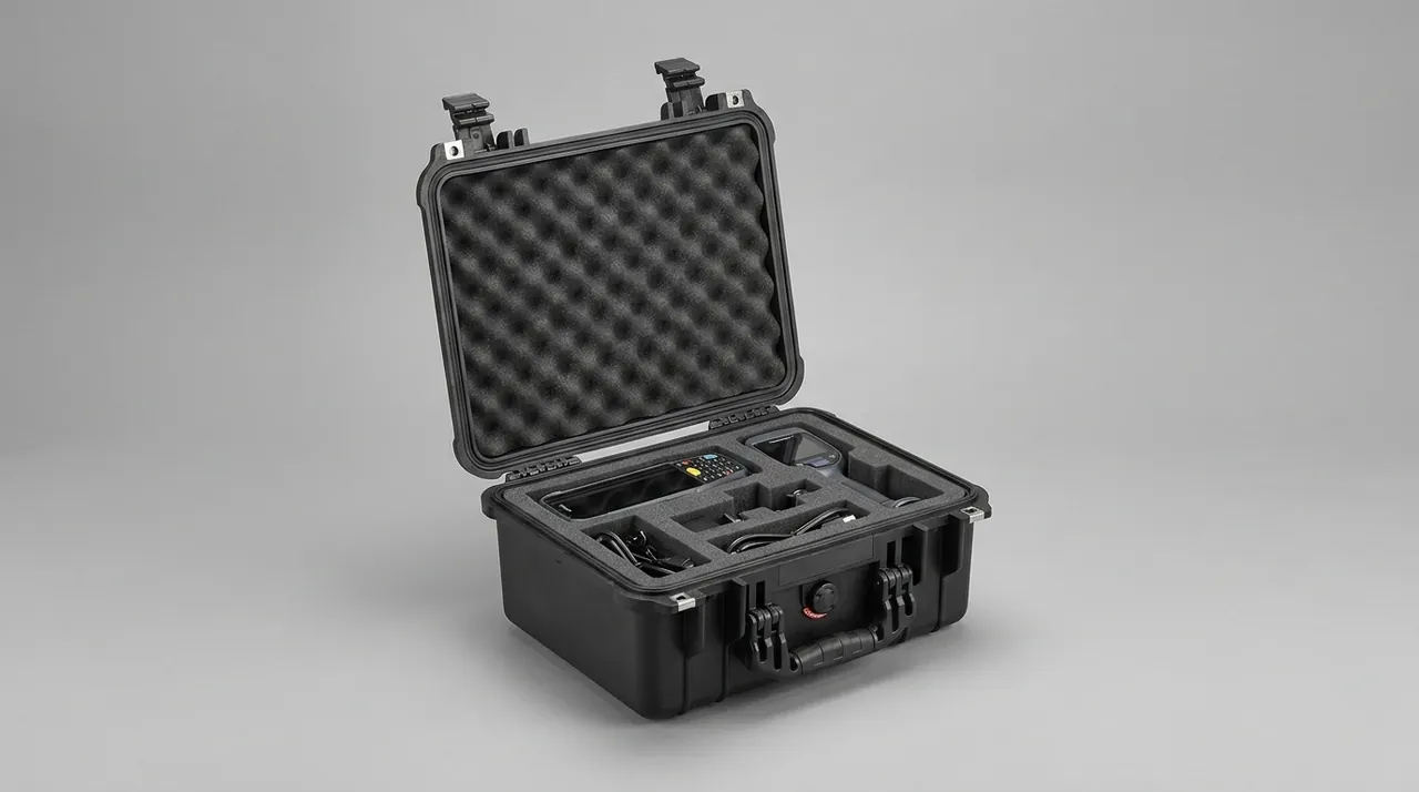
For control hardware, the case sealing class sets the risk level directly. An IP67 construction blocks rain spray and short-term immersion, but only while the gasket is intact and the latches apply even pressure. If a gasket is found with a groove pressed into it by grit, replace it rather than patching with tape.
Valves, flanges and pipe fittings: rust prevention and interface protection
The valves supplied with a fire pump set include the discharge gate valve, the check valve, the relief valve and the test valve, usually with cast iron or ductile iron bodies and bronze or stainless steel stems. The main transport problems are corroded threads and flange faces, and handles or stems broken by leverage loads.
Coat all exposed threads with a long-life anti-seize grease and fit plastic caps. Apply peelable protective film to flange faces. Where a handle cannot be removed, set limit blocks on both sides so that no lever arm can develop. Valve bodies and fittings should be arranged by bore size: place large valves lengthwise along the long side of the case, and put small fittings in compartmented trays on separate levels so they cannot migrate through the gaps around heavier items.
Because valves in a fire main sit idle for long periods and then have to operate on demand, stem and handwheel freedom is itself a reliability metric. If dust enters the stuffing box in transit, the valve will bind when it is finally operated. The case should therefore present no obvious dust path when closed, which depends on the fit accuracy of hinges, latches and gaskets; the structural points are covered in toolbox hinge, latch and seal design.
Piping hardware also includes grooved couplings, flange gaskets and bolts. Gaskets are consumables and should lie flat in a closed box rather than being rolled; bolts should be bagged by size with the size and quantity marked, so nothing gets mixed up on site. Galvanised fittings should not touch stainless steel parts, because galvanic corrosion accelerates in a damp environment.
What IP67 actually means: IEC 60529 and GB/T 4208
The water resistance of a case has to be expressed as a verifiable rating rather than an adjective. The international basis is IEC 60529, and the corresponding Chinese standard is GB/T 4208, which covers degrees of protection provided by enclosures using the IP code. Both define IP67 in the same way: the first digit of 6 means dust-tight, and the second digit of 7 means that under the specified test conditions, short-term immersion of the enclosure in water, typically 1 m depth for 30 minutes, produces no harmful effect.
| Rating | Dust protection | Water protection | Typical transport scenario |
|---|---|---|---|
| --- | --- | --- | --- |
| IP54 | Limited dust ingress | Splash resistant | Short road legs, covered storage |
| IP55 | Dust protected | Water jet resistant | Urban distribution, site transfer |
| IP65 | Dust-tight | Water jet resistant | Short-term outdoor storage |
| IP66 | Dust-tight | Strong water jet resistant | High-rainfall regions, open unloading |
| IP67 | Dust-tight | Short-term immersion | Sea freight, monsoon season, flood-prone yards |
One caution is needed. IP67 is an enclosure rating: it describes how hard it is for external water and dust to enter, and it is not the same as permanent humidity control inside the case. Internal humidity also depends on the moisture vapour transmission rate of the gasket material, on the breathing effect caused by temperature cycling, and on desiccant capacity. For humidity-sensitive items such as controller modules and mechanical seals, the correct approach combines an IP67 enclosure with internal humidity management. Rely on the enclosure alone and you may still find condensation on the inner wall after a sea voyage.
On verification, the buyer can request an immersion test report to IEC 60529 or GB/T 4208, and should check whether the test sample used the production configuration, meaning the same gasket cross-section, latch count and wall thickness as the delivered goods. For the custom cases typical of this sector, a sealed design with a pressure equalisation valve maintains IP67 while relieving the differential pressure caused by temperature cycling; the principle is described under case pressure equalisation valves.
How the IK impact rating maps to case structural strength
IP addresses water and dust; IK addresses impact energy. The IK scale comes from IEC 62262 and states, in joules, the ability of an enclosure to withstand external mechanical impact. On a fire pump project the site hazards include forklift contact, swinging loads during lifting, drops from stacks and shifting heavy items inside the vehicle.
| IK code | Impact energy | Typical scenario |
|---|---|---|
| --- | --- | --- |
| IK06 | 1 J | Small cases, careful manual handling |
| IK07 | 2 J | Manually carried transfer cases |
| IK08 | 5 J | Workshop transfer with frequent forklifts |
| IK09 | 10 J | Outdoor sites, multi-shift loading |
| IK10 | 20 J | Heavy components, frequent lifting |
It must be said that the IK code describes the shell itself, and it does not mean that internal parts see impact reduced by the same proportion. What determines whether an impeller or a mechanical seal survives is how much the insert system attenuates the external shock. In engineering terms the case is the structural skeleton and the insert is the second-stage attenuator, and neither works alone: an under-stiff case deforms heavily at the contact point and passes energy straight into the insert, while an under-stiff insert lets the part move and collide a second time.
When discussing selection, therefore, state three things together: the case IK rating, the ratio of insert material behaviour to payload weight, and the maximum drop height that must be survived. Casings above roughly 150 kg normally need a rotationally moulded or injection moulded case with stiffening ribs plus a base pallet, whereas light precision items such as seals and transmitters can travel in a portable case where the design effort goes into cushion thickness and location accuracy. Those thresholds are engineering experience ranges, and the component supplier's stated fragility should govern.
Blocking salt fog and high humidity on sea freight
Coastal projects, island installations and export orders spend long periods in salt-laden damp air. The corrosion risk to metal parts can be assessed using the neutral salt spray method of GB/T 10125, and buyers can ask the supplier for salt spray results on case hardware such as hinges, latches and telescopic handles, checking whether stainless steel or a plated finish was used.
Corrosion control works in three layers. The material layer keeps harmful chemistry off the parts: inserts that stay in contact with metal should avoid sulphur or halogen bearing compounds, because open-cell foam with high compression set absorbs moisture and then acts as a carrier for corrosive media. The atmosphere layer uses vapour-phase corrosion inhibitor material to form a monomolecular protective film on metal surfaces, which suits parts with complex geometry that cannot be greased individually. The barrier layer uses the sealed case plus desiccant to hold relative humidity at a low level, cutting off the electrolyte that electrochemical corrosion needs.
For casings and fittings that already carry galvanising or paint, watch for localised corrosion initiated by mechanical damage. A small scratch disables the coating locally and becomes a pitting site in damp conditions. The insert must therefore avoid hard contact with the payload; low-cost inserts made from recycled material often have uneven hardness and will abrade the coating under vibration.
Do not mix dissimilar metals in one case either. Stainless steel clamps in prolonged contact with galvanised bolts form a galvanic couple in damp conditions. Where space constraints force mixed loading, put an insulating barrier between them. For a fire pump, the as-delivered condition is effectively the long-term condition, which is worth stating explicitly in the packing work instruction.
The emergency spares case: designed for install-on-arrival
Fire pumps are installed in plant rooms, pump houses and fire control rooms, and those sites share a schedule characteristic: once the goods arrive, installation has to proceed quickly so that the fire acceptance inspection can be booked. A well-designed case can serve as both transport container and site spares cabinet, cutting out a handling and unpacking cycle.
Four design points matter. First, zoning should follow assembly sequence rather than weight, so that pump body, impeller, seal, coupling, controller and valves are reached in the order they are fitted, allowing the crew to work from one end to the other. Second, labelling should be systematic: every cavity carries part number, description, quantity and the set number it belongs to, and on multi-pump projects such as duty-standby-duty arrangements each set gets its own colour code. Third, consumables get their own zone: mechanical seals, gaskets and O-rings live in a small dedicated box with space reserved for spares, so restocking later is straightforward. Fourth, documents stay with the case, with the packing list, installation drawing and conformity paperwork inside a waterproof document wallet fixed to the inside of the lid.
Where air freight or emergency transfer is involved, the case should also be practical to move by hand, for example with folding handles and castors, as described in case wheels and trolley handle selection. Fire protection projects run to fixed energisation dates, and whether spares can be installed the moment the crew arrives directly affects the commissioning and acceptance schedule.

Insert material selection: EVA, PE, PU and antistatic options
The insert is the highest-technology part of a protective case, and it governs both the shock attenuation curve and the location accuracy of the payload. Common materials include EVA, PE and PU foams and composite constructions. The table maps them against fire pump requirements.
| Material | Cushioning behaviour | Dimensional stability | Suitable parts |
|---|---|---|---|
| --- | --- | --- | --- |
| EVA | Medium to high, good recovery | Good, easy to CNC carve | Impellers, couplings, controller modules |
| PE foam | Medium, firmer | Good, low cost | Pump casings and fittings as underlay |
| PU foam | High, best energy absorption | Medium, degrades when damp | Impact-sensitive parts, transmitters |
| Composite insert | Stiffness designed zone by zone | Good | Mixed multi-part shipments |
One point is often missed during material selection: chemical compatibility with the payload. Soft materials containing plasticisers migrate into organic coatings over long contact and cause bloom, sulphur bearing compounds discolour copper alloys, and recycled stock varies in composition, so hardness variation and leaching can occur in the same sheet. For equipment that has both appearance and corrosion requirements, specify virgin material and carve the zoning rather than moulding it from regrind.
In the customisation workflow, the supplier usually needs the outline dimensions, weight, centre of gravity and fragility of each item, and then designs cushion thickness and restraining geometry from that input. JUNZHIJIA, manufactured by Kexin New Materials (Guangdong) Co., Ltd., builds inserts to fire pump set model and works with OEM and ODM programmes, matching cavities to impeller bore, seal type and controller cabinet dimensions, and can issue material and sealing performance documents for contractors to file with fire acceptance records.
Transport validation: ISTA, GB/T 4857, ASTM D4169 and MIL-STD-810H
A protection scheme cannot rest on experience alone; it needs reproducible transport testing. The usual references are:
- ISTA procedures, which build a test sequence from the real distribution chain and suit validation of a complete packaging scheme.
- GB/T 4857 series, the Chinese basic test methods for transport packages, covering vibration, impact, stacking and compression.
- ASTM D4169, a performance test standard for the distribution cycle, with test intensity selectable by transport mode and assurance level.
- MIL-STD-810H, a method standard for environmental testing that can be consulted for vibration, shock and temperature-humidity cycling methodology. It must be stated clearly that cases of this class are not military-certified products; the standard is cited only as a source of test methods and confers no military qualification of any kind.
A sensible programme runs in three stages, from light to severe. The first stage applies stacking and random vibration to check whether the insert collapses under sustained static load and low-frequency excitation. The second applies drop and inclined impact tests to check whether the restraining geometry survives a case-level fall. The third combines temperature-humidity cycling with vibration to check for condensation inside the case and for premature desiccant exhaustion. Related procedures are covered under ISTA transport testing procedures and GB/T 4857 transport packaging tests.
Acceptance criteria should include three items: no visible damage to components, key dimensions such as impeller wear ring diameter and flange flatness within tolerance, and no free particles or condensate inside the case. For controller modules, add insulation resistance measurement and a functional power-up check. Only when all three pass is the protection scheme validated.
Packing, marking and handover procedure
The same case and insert produce completely different outcomes depending on how they are packed, which is why the packing sequence should be written as an executable checklist and folded into factory inspection.
- Verify the list: count parts against the set number, and check for wet paint, missing anti-rust oil or absent thread caps.
- Clean and protect: clean flange faces and ports, apply anti-rust grease, fit caps and blind flanges.
- Load in sequence: place the heavy reference part first and lock its restraint, then mid-weight items, and finally precision and consumable items, with precision cavities kept away from the case walls.
- Manage humidity: size the desiccant charge to the transport duration and climate, and record the insertion date and expiry indication.
- Close and compress: check the gasket for foreign objects, then close the latches in diagonal order and confirm even feel.
- Mark and secure: apply set number, centre of gravity and lifting marks, and add a tilt indicator where required.
Handover should be signed jointly by sender and receiver on an unpacking record covering case condition, gasket condition, desiccant indication and component condition. If anything is abnormal, photograph it immediately and preserve the original insert condition so the cause can be traced to design or to handling. For export projects, markings should meet destination language requirements and carry both Chinese and English content to prevent misreading on site.
Frequently asked questions
Q: Can an impeller and valves share the same protective case? A: Not recommended, on performance grounds rather than convenience. An impeller is balance sensitive and needs its own cavity, restraint in two directions and no compressive load on the hub, because wear ring clearance is measured in fractions of a millimetre. Valves and fittings are heavy items that migrate under vibration and rub against whatever they touch. In a shared case a valve body becomes an impact source, and once a wear ring goes oval or a blade edge rolls over, the installed pump delivers reduced flow and higher shaft vibration, sometimes enough to trip a bearing temperature alarm. If freight cost forces mixed loading, three conditions make it tolerable: a rigid divider must separate the two functional zones completely, heavy items must sit on the base with their restraints locked, and the impeller cavity must stay clear of the case walls with at least 50 mm of cushioning between zones. The more robust answer is to split by component class and ship an assembled set in three cases, one for heavy castings, one for precision parts and one for electrical hardware.
Q: Should the mechanical seal be removed and packed separately before shipment? A: Removing it and using the original factory inner pack inside an individual shock cavity is the preferred route, because the mating faces of a mechanical seal are the most particle-sensitive surfaces in the whole pump. Flatness is verified with optical interference bands at the factory, and a single hard particle pressed between the rotating and stationary faces can start a micro-leak that only appears after tens of hours of running. Where the assembly sequence makes removal impractical, protect the seal in place: fit a protective sleeve over the chamber, avoid rigid axial clamping, and keep the seal strictly separated from bolts, gaskets and other loose metal, which behave like abrasive paper under vibration. Either way, place an indicating desiccant in the case so the seal sits at low humidity and the secondary O-rings do not absorb moisture and take a compression set. On arrival, inspect for oil traces, water traces and free particles, and clean the chamber before assembly rather than coupling straight to the motor.
Q: How do diesel-driven and electric fire pumps differ in protection requirements? A: The difference sits in the control and monitoring hardware rather than in the hydraulic end. An electric set carries a controller cabinet with the main board, dual power supply transfer and a soft starter, and that cabinet is the most moisture- and vibration-sensitive item in the shipment, so it needs antistatic bagging, an indicating desiccant and four-sided clamping rather than bottom padding alone. A diesel set adds batteries, fuel lines and an engine-mounted controller, so the emphasis shifts to leak containment, corrosion control and preventing fuel from reaching adjacent components. Batteries fall under dangerous goods transport rules and normally need separate declaration and packaging, never sharing a case with precision parts. Pipe stubs should be plugged so residual fuel cannot seep into the insert and soften or swell the foam. What does not change with the drive method is the strict part: pump body, impeller, mechanical seal and coupling protection standards are identical for both.
Q: Can a case genuinely achieve IP67, and how does a buyer verify it? A: Yes, provided the sample submitted for testing was built to the production configuration. IP67 under IEC 60529 and GB/T 4208 requires dust tightness plus no harmful effect after short-term immersion under the specified conditions, most commonly 1 m depth for 30 minutes. Verify three things. First, confirm the test sample used the same gasket cross-section, the same latch count and the same wall thickness as the delivered goods, because a thicker gasket or an extra latch can carry a test that the shipping build would fail. Second, confirm the report documents an internal inspection for water traces after the test rather than only stating that the unit still worked. Third, confirm the gasket has been tested for ageing and compression set, since sealing performance after a few years of opening and closing is what the project actually depends on. Also state plainly that IP67 covers the enclosure only, and that internal humidity still depends on desiccant and pressure equalisation working together.
Q: What does the IK impact rating mean for a fire pump case? A: The IK scale comes from IEC 62262 and expresses in joules how much external mechanical impact an enclosure withstands, running from IK06 at 1 J up to IK10 at 20 J. On a fire pump project the realistic hazards are forklift contact at a loading bay, a swinging load during lifting, a drop from a stack, and heavy items shifting inside the vehicle. Heavy-component cases therefore normally need IK09 to IK10 strength, which in practice means stiffening ribs, reinforced corners and a base pallet. What matters just as much is understanding the limit of the rating: IK describes the shell only, and the shock that reaches an impeller or a mechanical seal depends on how much the insert attenuates. Case and insert form two stages in series, so specify all three parameters together, the case IK rating, the insert material relative to payload weight, and the maximum drop height that must be survived, and ask the supplier for the drop height behind any IK claim.
Q: How should moisture and salt fog be handled for export to hot, humid or coastal regions? A: Work in three layers. At the material layer, specify virgin closed-cell insert stock and avoid sulphur or halogen bearing compounds, because foam that absorbs moisture becomes a carrier for the chemistry that drives corrosion. At the atmosphere layer, add vapour-phase corrosion inhibitor material so complex metal geometry, which cannot be greased item by item, receives a protective film instead. At the barrier layer, rely on the sealed case and an adequate desiccant charge to hold internal relative humidity low, which cuts off the electrolyte that electrochemical corrosion needs. Ask the supplier for salt spray results to GB/T 10125 on hinges, latches and telescopic handles, and check whether stainless steel or a plated finish was used. Finally, never mix dissimilar metals in one case: stainless steel clamps in direct contact with galvanised bolts form a galvanic couple in damp air, so an insulating barrier is required wherever mixed loading cannot be avoided.
Q: Does a pressure equalisation valve on the case compromise water resistance? A: A properly designed valve does not compromise IP67, and on most sea freight routes it improves the outcome. Temperature cycling creates a pressure differential across a sealed case. Without relief, the interior can develop condensation as the case cools, and the lid can be hard to open because of negative pressure. A pressure equalisation valve vents slowly through a micro-orifice or a waterproof breathable membrane while blocking liquid water and dust, so the enclosure still resists immersion. When selecting, confirm three points. Check that the valve body genuinely incorporates a breathable membrane rather than a simple plug. Check that its mounting position avoids standing water and avoids direct spray on the upper face. Check that the joint to the case wall is integrally formed, because a valve fitted as an afterthought is a common source of leakage. Combined with desiccant, an equalisation valve sharply reduces the condensation seen when a case is first opened after a long voyage.
Q: Is custom insert tooling expensive, and how should small batches be handled? A: It depends on the process route rather than on the size of the order. Carved inserts suit small and medium batches across several models: there is no steel mould to cut, the supplier only needs outline dimensions, weight, centre of gravity and fragility for each item, and a later design change costs little because the programme is edited rather than retooled. Moulded foam suits high volumes with fixed cavity geometry, where the piece price is low but a one-off tooling investment is required, and the order of magnitude is discussed in custom case mould cost analysis. Fire pump projects are typically multi-specification and low volume, so the sensible sequence is to validate fit with a carved insert first and release volume production only after location accuracy and drop behaviour are confirmed. JUNZHIJIA supports model-matched inserts and OEM and ODM programmes, so a single-cavity sample can be built against a drawing or a scanned part before any commitment to moulding.
Q: What must be checked during unpacking acceptance on arrival? A: Work through a short list in a fixed order and record the result. Inspect the case exterior for drop deformation and damaged latches. Inspect the gasket for grit marks, cracks or loss of rebound. Read the desiccant indicator to confirm it has not expired early. Inspect the insert for collapsed cavities or shed debris. Inspect the components for chipped flange faces, corroded threads and abraded coatings, and check an impeller wear ring for roundness where a gauge is available. Confirm the packing list, installation drawing and conformity paperwork are complete. For a controller module, add an insulation resistance measurement and a power-up self-test before installation. Both parties sign the record, and any anomaly is photographed with the original insert condition preserved, so the cause can be traced either to the protection design or to handling.
Conclusion and further reading
Four things decide whether a fire pump set survives its journey: clean, dry seal faces; impellers in individual cavities with two-direction restraint; controller modules bagged, clamped and desiccated; and a case whose IP67 and IK claims can be tested rather than assumed.
Further reading