

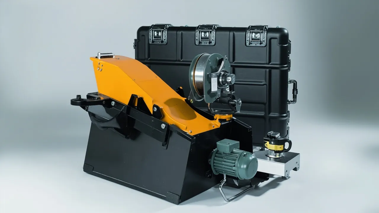
Transit damage to a hoist usually happens before it is ever hung on a beam. A motor shaft extension is chipped and burred, so the coupling misaligns and the unit vibrates in service. A brake friction face picks up oil or dust, so braking torque is short and the load slips. A gearbox oil seal is crushed out of shape, so the unit weeps from its first week. A hook or sheave rope groove is struck, so the wire rope wears prematurely. A limit switch is broken, so the safety protection fails. These faults are hard to spot during incoming inspection and surface only at commissioning, when the only remedies are rework or downtime. The conclusion is clear: a hoist motor and brake are heavy-load, safety-related components, a gearbox and drum are precision fits, and a hook and wire rope are load-bearing safety items. Their outer packaging must be a dedicated parts case with separated-cavity location, verified load paths, contamination and moisture control, and vibration-damped support - not a crate stuffed with filler, not stretch wrap, and not bare parts tied together.
Three characteristics set hoist components apart. In the trade this packaging category is generally called an electric hoist case, subdivided by model, with brake component cases often planned separately, and all brought under one numbering and traceability system for lifting equipment cases. The first is their safety role. The brake is the last line of defence against a falling load, and the cleanliness and flatness of its friction faces directly govern braking torque. Any oil, dust, or score can cause brake failure, which is an intolerable risk. The second is their heavy-load nature. Motors, gearboxes, and drums are heavy with high inertia, so transit shock travels through them to shaft extensions, bearings, and case structure, and the damage accumulates. The third is compound sensitivity. An electric hoist contains a motor with windings and insulation, a brake with friction pair and springs, a gearbox with gears and oil seals, a control box with contactors and a PCB, and a hook and wire rope as load-bearing items. Each needs a different protection logic, so grading is essential.
This article is written for hoist manufacturers, specialist electric hoist factories, lifting equipment distributors, and project buyers. It sets out graded protection schemes for motor and brake components, insert and load-path design, standard validation methods, and on-site acceptance rules, and it explains the engineering capability behind custom inserts and OEM/ODM supply.
Table of Contents
- 1. Why Hoist Components Need a Dedicated Parts Case
- 2. Hoist Motor and Brake Component List and Protection Class
- 3. Failure Modes: Brake Face Contamination, Shaft Extension Deformation, Gearbox Weeping and Rope Groove Damage
- 4. Load Ratings and Packing Strategy
- 5. Case Structure and Material Selection for Hoist Motor Assemblies
- 6. Insert Design: Axial Location, Brake Face Protection and Suspension Fixing
- 7. Protecting Wire Rope, Hooks and Sheave Blocks
- 8. Protecting Electrical Parts: Limit Switches, Control Boxes and Encoders
- 9. Brake Dust and Moisture Control plus Case Ingress Protection: IEC 60529 / GB/T 4208
- 10. Rust Prevention and Cleanliness Control
- 11. Load Testing and Acceptance Awareness
- 12. Vibration and Shock Validation for Hoist Components: GB/T 4857 and ISTA
- 13. Stacking, Lifting and Load-Handling Awareness for Hoist Cases
- 14. OEM/ODM Customization: Acceptance and Maintenance for Hoist Cases
- Frequently Asked Questions
- Conclusion & Related Reading
1. Why Hoist Components Need a Dedicated Parts Case
A hoist is a classic heavy-load, safety-related, electromechanical machine. Its components are machined to demanding accuracy, and much of that accuracy is squandered at the packaging step.
The brake is a safety item that tolerates no contamination. Conical-rotor braking, electromagnetic disc braking, and mechanical braking all depend on friction pair contact. Oil on a friction face sharply reduces the coefficient of friction and braking torque. Dust or grit scores the face and causes uneven wear. A hard impact creates a local high spot that reduces contact area. Such problems may not show in a static inspection but surface under load braking, and brake failure is the highest-risk failure mode in lifting work.
The motor is a component whose precision lives in its fits. The shaft extension mates with a coupling or gearbox input shaft. Its diameter tolerance, keyway, and axial location determine alignment accuracy. Once the extension is burred, bent, or its keyway deformed, assembly runs eccentric, showing up as vibration, noise, and early bearing wear, and in severe cases as a broken shaft.
The gearbox is a component whose precision lives in gear and shaft train. Gear tooth accuracy, bearing clearance, and oil seal contact are set at the factory. Transit shock causes micro-pitting on tooth flanks, brinelling of bearing races, and deformation of seal lips. Seal deformation shows as weeping after installation, which both contaminates the environment and degrades lubrication.
Hooks and wire rope are load-bearing safety items. The hook throat, the critical section, and the threaded shank must have no cracks, deformation, or impact damage. Wire rope strands and core, once crushed by a hard object or cut by a sharp edge, suffer broken wires and reduced diameter, cannot be repaired on site, and must be replaced as a whole.
Contamination and moisture are concealed failure sources. Motor windings and terminals are moisture sensitive, and moisture lowers insulation resistance. If gearbox breathers and oil ports are left open, dust and water vapour enter and contaminate the lubricant. Contactors and PCBs in the control box are sensitive to dust, moisture, and ESD.
Key reminder: hoist component damage is cheap to prevent, expensive to reverse, and safety-relevant. The consequence of brake face contamination caused by poor packaging is not merely rework cost but on-site safety risk.
For a hoist factory, the case matters beyond protection: it standardises the dispatch step. Collapse the case range into a few load-rating grades and cover the different models with swappable plates, and the warehouse no longer needs a dedicated position per model, while handling gear and inspection items shrink with it. Reuse limits and discard criteria are covered in protective case service life and reuse years.
2. Hoist Motor and Brake Component List and Protection Class
Protection logic differs markedly between components, so grade each item before packing.
| Component | Typical material / structure | Critical sensitivities | Recommended protection |
|---|---|---|---|
| --- | --- | --- | --- |
| Hoist motor | Cast aluminium or iron housing, shaft extension | Shaft extension, keyway, terminal chamber, insulation | Isolated cavity + shaft sleeve + barrier bag |
| Conical rotor motor | Axially movable rotor | Axial clearance, brake spring | Axial stops + isolated cavity |
| Electromagnetic disc brake | Armature, friction disc, springs | Friction faces, armature flatness, springs | Divided cavity + face film + pre-compressed springs |
| Mechanical brake | Pawl, ratchet, band | Ratchet teeth, band face | Isolated cavity + tooth guard |
| Gearbox | Cast housing, gears | Tooth flanks, bearings, seals, joint faces | Shaft sleeve + port caps + baseplate location |
| Drum assembly | Drum, rope groove, bearing housings | Rope groove, journals, flanges | Cradle support + groove film |
| Hook and hook block | Forged body, sheaves | Throat, critical section, thread | Suspension fixing + throat guard + thread sleeve |
| Wire rope | Steel strands, core | Broken wires, diameter, corrosion | Large-diameter coiling + end fixing + anti-rust film |
| Sheave and sheave block | Cast iron or nylon wheel | Rope groove, rim, bearings | Dedicated slot + groove guard |
| Rope guide and spooling device | Cast iron or steel | Threaded rod, guide face | Divided cavity + thread sleeve |
| Control box and contactors | Sheet-metal box, electrical parts | Moisture, dust, ESD | Barrier bag + ESD bag + damped support |
| Limit switch and encoder | Electromechanical, electronic | Contacts, code disc, cable | Small-parts box + ESD packaging |
| Pendant and control handle | Plastic shell, pushbuttons | Buttons, cable, housing | Small-parts box + coiled and secured cable |
| Coupling and gear sleeve | Alloy steel, nylon | Tooth flanks, fit bores | Isolated cavity + anti-rust paper |
| Fasteners and pins | High-strength alloy steel | Threads, fit surfaces | Compartment box + anti-rust paper |
The table shows that brake face cleanliness and motor shaft extension accuracy are the two physical protection themes, while the integrity of load-bearing items, hooks and wire rope, forms a third non-negotiable theme.
3. Failure Modes: Brake Face Contamination, Shaft Extension Deformation, Gearbox Weeping and Rope Groove Damage
Brake friction face oil and scoring. The friction coefficient of a friction pair is extremely sensitive to contamination. Oil comes from oil seals, lubricated parts, or an uncapped gearbox port sharing the case. Dust comes from crate wood dust, cardboard fibre, and case reuse residue. Scores come from contact with other metal parts. Any of these reduces or unbalances braking torque, which is a safety-relevant, unacceptable failure.
Permanent deformation of brake springs. A brake relies on spring preload. If a spring stays compressed in transit or suffers inter-coil impact, it takes a permanent set, so preload is short and the brake responds late or the load slips.
Motor shaft extension deformation and keyway damage. The shaft extension is a fit surface. Impact causes burrs, bending, or keyway deformation, and assembly then runs eccentric, producing vibration, noise, and early bearing wear. Because the extension is a cantilever, the lever effect amplifies any force, so it is struck more often than other areas.
Gearbox seal weeping and joint face seepage. Seal lips take a permanent set after compression or heating, and sealing compound at joint faces can crack under shear shock. Both show as weeping early in operation.
Gear flank micro-pitting and bearing brinelling. Shock load causes local plastic deformation and micro-pitting on tooth flanks, the starting point of later fatigue spalling. Bearing races brinell under shock load, producing noise and temperature rise.
Drum rope groove and flange damage. The rope groove is the formed surface guiding the rope onto the drum; damage causes erratic spooling and uneven rope wear. A damaged drum flange edge shears the rope at the edge.
Hook throat and critical section damage. A hook throat opens further under load when deformed, so impact damage creates stress concentration. Scores and cracks at the critical section are a major hazard and must be strictly avoided.
Broken wires, crushing, and corrosion in wire rope. Crushed by a hard object, cut by a sharp edge, or over-bent, wire rope develops broken wires and reduced diameter. Stored or shipped in a humid environment without rust protection, it corrodes and loses breaking strength.
Electrical moisture ingress and insulation loss. Motor windings, terminals, and control boards lose insulation resistance when moist, and in severe cases trip on energising or oxidise contacts.
4. Load Ratings and Packing Strategy
Hoist component weights span a wide range, so packing strategy must be tied to load rating.
| Load rating | Typical components | Component weight | Packing strategy | Key risk |
|---|---|---|---|---|
| --- | --- | --- | --- | --- |
| Micro (0.25-1 t) | Miniature motors, small brakes | 5-30 kg | One-person carry case + divided cavities | Impact, mixing |
| Small (1-3 t) | Standard motors, gearboxes | 30-120 kg | Two-person or wheeled case + stops | Drop during handling, shaft damage |
| Medium (3-10 t) | Motor-gearbox assemblies, drum sets | 120-400 kg | Heavy-duty case + lifting points | Unbalanced lift, structural deformation |
| Large (10-30 t) | Large drums, hook blocks | 400-1,500 kg | Base pallet case + multi-point lifting | Offset centre of gravity, case instability |
| Very large (over 30 t) | Split drums, large hook blocks | Over 1,500 kg | Steel base case + dedicated rigging | Transport permits, structural strength |
Four grading principles apply. First, grade by handling method: below 20 kg one person can carry, 20-50 kg needs two people or an aid, and above 50 kg requires lifting points or forklift pockets. Second, grade by safety class: safety-related items such as hooks, wire rope, and brakes should be cased or cavitied separately from ordinary parts, with a clear safety-item marking on the case. Third, grade by stiffness and cantilever: cantilevered items such as motor shaft extensions and rope guide threaded rods need dedicated sleeves or supports so the cantilever does not become a load lever. Fourth, grade by weight and centre of gravity: above 400 kg per item, verify and mark the centre of gravity and arrange lifting points symmetrically.
5. Case Structure and Material Selection for Hoist Motor Assemblies
A hoist component case has to satisfy three demands that pull against each other: carry an assembly weighing several hundred kilograms, keep the brake friction face away from the slightest trace of oil, and leave a cantilevered part such as a motor shaft extension completely unloaded. Selection lands where capacity, stiffness, tare weight, and sealing balance out.
| Case type | Body material | Rated unit load | Structural trait | Hoist components it typically carries |
|---|---|---|---|---|
| --- | --- | --- | --- | --- |
| Small injection case | PP / PE | Up to 30 kg | Fine compartments, nestable | Limit switches, pendants, encoders, connectors |
| Standard rotomoulded case | LLDPE | Up to 120 kg | One-piece moulding, tough | Standard motors, small gearboxes, brake assemblies |
| Heavy-duty rotomoulded case | LLDPE with thickened base | Up to 400 kg | Base carries load, lifting points fitted | Motor-gearbox assemblies, drum sets |
| Frame composite case | Aluminium profile plus composite panels | Up to 800 kg | Takes load columns and forklift pockets | Large drums, hook blocks |
| Steel-base pallet case | Steel base with case cover | Over 800 kg | Shortest load path, multi-point lifting | Very large split components, rigging sets |
Four selection criteria specific to hoists. First, the brake cavity must be an oil-free zone: no plastic part or gasket sharing that cavity may be soft PVC containing plasticiser, because plasticiser migration forms an oil film on the friction face and cuts braking torque directly. Second, for cantilevered parts judge the case stiffness rather than the insert softness: damage to motor shaft extensions and rope guide threaded rods usually starts with the case deforming during lifting or stacking and passing that displacement to the free end, so ribs and base thickness on a heavy case do more than a thicker insert. Third, treat salt spray as the default condition on sea freight: transfer cycles are long, so latches, hinges, and steel parts must be selected and finished for a salt-spray environment rather than carrying over an inland specification. Fourth, match the hardware to the total weight: latch, hinge, and handle capacity must suit the loaded case, so the case does not survive while a latch fails first. Hardware and gasket design are covered in case hinges, latches and sealing structure.
6. Insert Design: Axial Location, Brake Face Protection and Suspension Fixing
The insert is the functional core of a parts case. For hoist components it must solve location, cushioning, isolation, and cleanliness at once.
Motors: axial stops plus shaft sleeve. Fix the motor in both axial and radial directions. Radially, use a contoured cradle covering more than a half circle for surface contact at low stress. Axially, fit stop blocks at both ends so the motor cannot travel. The shaft extension must be sleeved in plastic or a soft tube covering the whole extension including the keyway. Cap the terminal chamber entry so dust and moisture cannot enter.
Brakes: friction face film plus pre-compressed springs. The friction faces must be filmed for isolation, with film material that is oil-free and free of plasticizer migration so it cannot contaminate the friction material. Springs should be fixed in a pre-compressed state so transit cannot create free vibration and inter-coil impact. Disc spring stacks should be fixed in their as-assembled state and never broken up or mixed.
Gearboxes: baseplate location plus port caps. Carry the gearbox on its baseplate and reinforced areas, and fit stop blocks around the perimeter to limit horizontal travel. Cap every oil port, breather, and filler. This is the single most important measure against leakage and contamination in transit. Orient the shaft extension with the case stiffening direction so it does not take shock directly.
Drum assemblies: cradle support plus groove film. Seat the drum journals in cradles for surface contact, film the rope groove against scoring, and fit guards on the flange edges. Long drums need a mid-span support.
Hooks: suspension fixing plus throat guard. Suspend the hook so the body does not rest on the case floor, reducing impact risk. Guard the throat against deformation and sleeve the thread. Sheaves in a hook block should be in their own cavity with the rope groove filmed.
Control boxes and electrical parts: isolated damped cavity plus moisture and ESD control. Support the control box on damping pads with clearance for cushioning. Fit a barrier bag with desiccant and a humidity indicator card, and pack PCB-containing parts in anti-static shielding bags.
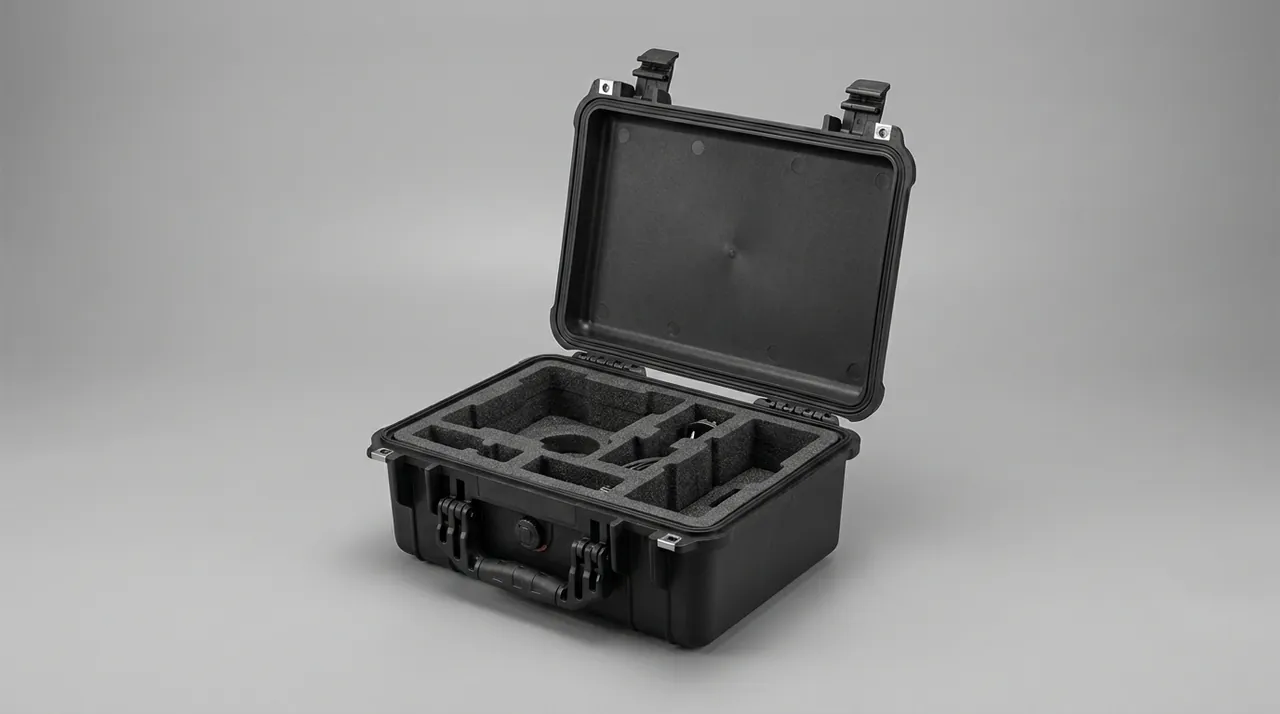
How to build the insert depends first on how many models you run. A hoist range is usually messier than a bore series: within one load rating there are single-speed and two-speed versions, single-rope and double-rope, standard and explosion-proof. With few models and small batches, routing the whole cavity by CNC is the most direct answer, and a model change only means a new toolpath. With many models, split the insert into three layers: a universal base, a model plate, and a dedicated brake cavity. Batch-produce the plates as die-cut EVA, so a model change swaps only the middle layer. The brake cavity must be physically separated from oil-bearing items such as oil seals and gearboxes, and that separation should be a rigid divider rather than foam, because compressed foam forms a creep path for oil along its face. Process and tolerance control are set out in custom foam insert design guide, and energy-absorbing structure design in shock-absorbing cushion liner cases. Where a single case must carry several different components, a removable divider system markedly improves adaptability; see case removable divider system design.
JUNZHJIA, manufactured by Kexin New Materials (Guangdong) Co., Ltd., provides custom contoured insert design based on hoist model, motor and gearbox outline, hook block dimensions, and centre of gravity, and supports a 3D insert concept before physical sampling.
7. Protecting Wire Rope, Hooks and Sheave Blocks
Wire rope, hooks, and sheave blocks are load-bearing safety items with a completely different protection logic from other parts: no repair is permitted, only replacement.
Coiling and securing wire rope. Coil wire rope on a large-diameter reel or in large-radius loops. The bend radius must not fall below the manufacturer's recommendation, typically no less than six to ten times the rope diameter depending on construction. Secure both ends after coiling so the strands cannot loosen or form a kink on unreeling. Wire rope must never contact a sharp edge, be crushed by a heavy object, or be sharply bent.
Rust protection for wire rope. Wire rope corrodes readily in humid conditions. Coat it with rust-preventive grease or wrap it in vapour corrosion inhibitor film, and put desiccant in the case. Sea freight projects need particular attention to salt spray and reinforced barrier packaging where necessary.
Protecting the hook externally. The hook throat and critical section must have no impact damage. Suspend the hook so the body hangs free, guard the throat, and sleeve the thread. Keep clearance to the case wall so nothing strikes it in transit.
Protecting sheave grooves. The sheave groove is the formed surface that mates with the rope; damage causes uneven rope wear and broken wires. Use a dedicated cavity, film the groove, and guard the rim. Fit dust caps to sheave bearing housings.
Protecting the rope guide threaded rod. The threaded rod and guide faces of a rope guide govern spooling quality, so sleeve the thread and use a dedicated cavity.
Consistency management for matched items. Wire rope, rope clips, wedges, and pressure plates are matched sets and should be packed by unit with the pairing marked, so nothing is mixed on site. Rope handling and discard awareness can be built around the relevant wire rope practice for lifting machinery; note that the parts case described here serves an outer packaging function only and does not change the mechanical properties of the rope.
8. Protecting Electrical Parts: Limit Switches, Control Boxes and Encoders
Hoist electrical parts share one trait: they carry a protective function rather than a purely controlling one. If the over-hoist limiter or the upper limit switch fails, the hook runs straight into the top. The packaging objective is therefore not "good enough to work" but "arrives with its actuating position exactly as it left the factory."
Keep the control box in its original packaging, then add a high-barrier bag. Contactors, relays, and terminal blocks inside the box fear moisture above all, and damp conditions oxidise contacts and drop insulation resistance. Retain the factory packaging, wrap it in an aluminium-laminate or high-barrier film bag with desiccant and a humidity indicator card, and let the site settle moisture exposure on opening. If fill material must be added inside an electrical enclosure, select it against UL94 flammability classifications rather than bringing combustible filler into the cavity.
Run inverters and encoders through ESD control. Inverters, soft starters, and encoders containing PCBs belong in anti-static shielding bags, unpacked and wired under ESD-controlled conditions. Ordinary bubble film generates static through friction and must not wrap a PCB directly.
Protect limit switches in their preset state. Upper limit switches and over-hoist limiters leave the factory with their actuating position set for a given model. Park the mechanism unloaded, keep the shims and lever accessories with the switch, and store it in a compartmented small-parts box so transit cannot press or strike it into a shifted position. A shift is hard to notice on site, yet it directly weakens top-of-travel protection.
Give the encoder its own damped cavity. The code disc inside an encoder is very sensitive to shock and vibration, so provide a separate damped cavity with clearance around it and keep it out of any cavity holding heavy items.
Pendant and cables. Pendant housings and buttons damage easily, so a small-parts box is preferable; coil control cables at a large radius and secure them so pulling cannot break conductors internally, and cap the plugs.
Note on temperature extremes. Where a route may see low or high temperatures, electrical material properties, grease consistency, and battery performance are all affected; see extreme temperature protective case design.
9. Brake Dust and Moisture Control plus Case Ingress Protection: IEC 60529 / GB/T 4208
On a hoist case, the first question an IP rating answers is not "will it get rained on" but "can dust reach the brake friction face". A brake tolerates particles almost to zero, and a single dust ingress can make braking torque unpredictable at the next loaded stop.
Set the class from the route, and leave no margin on cases with electrical parts. In-plant circulation and covered short-haul delivery are served by IP54. Domestic long-haul road transport with open storage in wet regions calls for IP65. Export sea freight, quay transfer, and long-term open storage call for IP67. Any case holding a motor, control box, or encoder should reach IP67 as a complete unit, because motor insulation is highly sensitive to condensation, and condensation is not confined to sea freight: inland routes with large day-night temperature swings trigger it just as readily.
The standard judges the enclosure, not the component. IEC 60529 and GB/T 4208 set out enclosure test methods: IP65 means dust-tight plus protection against water jets, IP67 means dust-tight plus temporary immersion. It must be stated plainly that these standards judge the enclosure alone. They do not stand in for cushioning, location, and cleanliness design inside, they say nothing about whether the motor, brake, or encoder inside meets the same class, and they say nothing about the machine as a whole.
High ratings are hard on a big case because the sealing face is so long. Drum sets and assembly cases are large with long openings, so the sealing perimeter grows and flatness plus uniform compression degrade quickly. Enlarging the gasket section usually backfires, because uneven compression creates local failure. The effective route is denser latches, multi-point simultaneous clamping, case stiffness sufficient to control deflection, and a machined sealing face that holds flatness.
On heavy long cases, fit a pressure equalisation valve. A sealed case develops a differential across air freight, high-altitude transport, and day-night temperature swings, and that differential lifts the gasket or bulges the case wall at its weakest point. On an IP67 case, fit a pressure equalisation valve that passes air but not water, so the differential is relieved without giving up sealing. The longer the case and its sealing face, the more necessary this becomes.
Replace the gasket as a consumable. After every reuse, check compression set, ageing cracks, and embedded grit. On a case holding a brake or a motor, a failed gasket costs more than moisture damage, because it lets dust straight onto the friction face. Hardware life management and gasket replacement intervals are covered in protective case service life and reuse years.
10. Rust Prevention and Cleanliness Control
Hoists contain many steel parts and machined surfaces, so rust prevention and cleanliness control run as two parallel lines.
Three categories of corrosion risk. The first is exposed machined surfaces such as motor shaft extensions, drum journals, gear tooth flanks, and hook threads. The second is structural steel parts such as drum shells, frames, and rope guides. The third is slender or elastic parts such as wire rope and springs. Strategies differ: machined surfaces take rust-preventive oil plus vapour corrosion inhibitor film; structural parts take coating plus barrier packaging; wire rope and springs take rust-preventive grease plus desiccant.
Cleanliness matters especially for brakes and gearboxes. Brake friction faces tolerate no oil or particles, and gearbox internals must admit no dust or water. Controls include capping all oil ports, breathers, and fillers; filming brake friction faces for isolation; thoroughly removing debris after insert machining; physically separating the packing area from machining; and cleaning cases thoroughly before reuse.
Identifying contamination sources in packaging. Crate wood dust, cardboard fibre, low-density foam crumbs, floor grit, and hand sweat are all contamination sources. Prefer closed-cell, non-shedding insert materials such as EVA and IXPE, and wear clean gloves when packing so bare hands never touch machined surfaces.
The on-site value of humidity monitoring. A humidity indicator card is a low-cost diagnostic that delivers a definitive moisture verdict the moment the case is opened, providing evidence for liability allocation. For cases containing motors this matters particularly, because falling insulation resistance is gradual and easily missed.
11. Load Testing and Acceptance Awareness
Hoists fall within the scope of special equipment, with strict load testing and safety inspection requirements. Packaging does not change a machine's mechanical performance, but packaging damage directly affects test results.
What load testing involves. Lifting equipment normally undergoes static and dynamic load testing after manufacture or major overhaul to verify structural strength, braking reliability, and running smoothness. Static testing verifies load capacity and structural strength, while dynamic testing verifies the reliability of the travel mechanism and brake. These tests are performed by the machine builder or a qualified inspection body.
How packaging damage affects test results. First, brake face contamination directly reduces braking torque, appearing in static and dynamic tests as excessive braking distance or load slip. Second, shock damage to gears and bearings appears in dynamic testing as abnormal noise, vibration, and temperature rise. Third, motor shaft extension deformation causes misalignment, appearing as vibration and current fluctuation. Fourth, a shifted limit switch preset causes inaccurate limit protection. If these symptoms surface only at the test stage, the response is usually teardown inspection or even machine rework.
Moving acceptance awareness forward. The right approach is to move acceptance awareness forward to the unpacking step: complete visual inspection and critical dimension sampling before assembly, so packaging-induced damage is identified before assembly rather than at load testing.
Note on standard references. Awareness of load and stability requirements for lifting machinery can be built around the thinking in GB/T 3811 for crane design, and general hydraulic and mechanical safety around ISO 4413. Note that these are design and management references: the parts case described here performs an outer packaging function only and does not alter the mechanical or safety performance of the equipment. Load testing and safety inspection must follow the formal procedures of the machine builder and inspection body.
12. Vibration and Shock Validation for Hoist Components: GB/T 4857 and ISTA
Validation on a hoist case looks slightly different from ordinary heavy-item packaging: it is not only about whether a part moved, but also about whether a stop block loosened and whether the brake face picked anything up.
Vibration loosens the restraint first, then causes impact. Road transport vibration concentrates in the low-frequency band. Drums, long shafts, and rope guide threaded rods have natural frequencies close to that band and are easily excited; once excited, the part jumps inside the case and strikes the insert and case wall repeatedly, and the foam suffers compression fatigue and collapse. On heavy items such as motors, gearboxes, and drum sets, vibration has a less obvious effect too: fasteners loosen and stop blocks shift, so parts that were originally restrained gradually free themselves, and damage accelerates from that point.
For heavy items, shock is the dominant load. The high accelerations from loading drops, forklift impacts, and emergency braking pass from the base into the case and then through the insert and stop blocks into the part. The greater the mass, the stronger the inertial response, which is where shaft extension deformation, bearing brinelling, and case structural damage originate.
Choosing the standard set. Domestic projects should work to the GB/T 4857 series: random vibration verifies insert and location stability, stacking verifies the compressive capacity of case and contents, and drop verifies case structural strength. International projects can reference ISTA procedures and the ASTM D4169 distribution cycle, which suits combining test items to match a real distribution chain; see ASTM D4169 distribution cycle testing points. Where environmental robustness must be assessed, the relevant methods in MIL-STD-810H can be used as an evaluation basis, noting that the standard is an environmental test methodology reference, not a military certification.
Validate the first article as a whole case, then re-check the safety items. First-article validation should run on the complete case rather than a single part, because case stiffness, latch distribution, insert fit, and contents inertia act together. After testing, check five things: part displacement, insert compression set, case cracking, gasket condition, and hardware tightness, then iterate. For safety-related items such as hooks, wire rope, and brakes, add one visual and dimensional review after validation to confirm no hidden damage occurred. Environmental test usage is covered in MIL-STD-810H environmental testing and case compliance.
13. Stacking, Lifting and Load-Handling Awareness for Hoist Cases
Hoist assembly cases commonly weigh several hundred kilograms, and stacking plus lifting are the two actions most likely to go wrong.
Confirm the load path before stacking. Stacking capacity follows from case stiffness, insert support, and the contents together. Under heavy loads the part rather than the case wall often does the real work, so if a motor or gearbox housing cannot carry compressive load along its length, the design must switch to case-carries, contents-unloaded: fit load-bearing columns or frames in the insert so the upper load bypasses the part and runs into the case floor and pallet. Stacking tests can follow the relevant parts of GB/T 4857.
Lifting points follow the offset mass. A motor-gearbox assembly's centre of gravity sits toward the motor end, since the motor is a solid casting; a drum set's sits on the axis; a hook block's sits toward the sheave end, and none of the three is a centred block. Place lifting points symmetrically, mark the longitudinal centre-of-gravity position on the outside of the case, and give a rated load label. Handles and trolley handles are for manual pulling only and must never substitute for a lifting point.
Forklift and manual limits. Align forks with pallet openings or reinforcing beams so fork tips do not press into the case floor and injure the parts, and keep fork length sufficient to avoid an excessive cantilever. Treat 20 kg as the one-person limit, use two people or an aid from 20 to 50 kg, and require mechanical handling above 50 kg, with weight markings on both sides and on the top. Heavy cases should move mainly by forklift and lifting gear, with wheels reserved for level-ground adjustment.
Safety items deserve a separate mention. Hooks, wire rope, and brake assemblies must be set down gently, never thrown or dragged. Inspect visually immediately after unpacking, confirming the throat, critical section, and rope strands are sound before the item enters the assembly flow.
Boundary of the standard references. A hoist is lifting equipment, and load and stability awareness for lifting work can be built around the thinking in GB/T 3811 for crane design, with general hydraulic and mechanical safety around standards such as ISO 4413; the cleanliness requirement for a brake friction face and the discard criteria for a hook belong to the equipment's own service requirements. One boundary should be stated clearly: the case discussed in this chapter is responsible only for delivering components safely to the assembly line. It does not change braking torque, does not change hook breaking load, and plays no part in the machine's safety inspection verdict.
14. OEM/ODM Customization: Acceptance and Maintenance for Hoist Cases
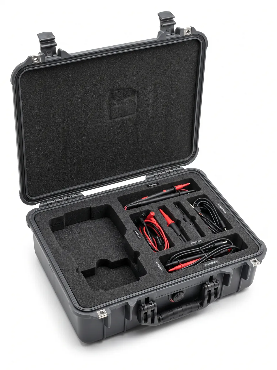
Customization for a hoist case usually starts with a model-versus-load-rating table. The sensible order is: plan the case series by load-rating grade and the number of models, settle the insert layering (universal base, model plate, dedicated brake cavity), run a first-article trial fit with clearance checks, add a round of vibration and drop pre-trials if needed, move into pilot production and volume supply, and finally iterate on site feedback.
When shortlisting a supplier, check four things: whether they can run a load-path and stiffness check on heavy items, the accuracy of insert machining and the level of cleanliness control, whether their test documentation covers tender requirements, and how stable volume delivery is. The methodology is set out in how to choose a protective case OEM factory. JUNZHJIA, manufactured by Kexin New Materials (Guangdong) Co., Ltd., has long supplied hoist manufacturers and specialist electric hoist factories with integrated case planning, contoured insert design, and volume delivery. It can build a standard case series around model and load rating, supply matched gaskets and hardware, and provide test documentation that supports tendering and acceptance. Counterfeit cases with substituted insert materials and hardware also circulate in this market, so buyers should verify actual compression and sealing behaviour; identification methods are described in identifying genuine versus counterfeit protective cases.
Acceptance points are best run in two layers. At case level: cracking, gasket integrity, latch and hinge function, lifting points and pallet structure, tamper evidence, and the humidity indicator card. At component level: motor shaft extensions and keyways for burrs or deformation, brake friction faces for oil and scores, gearbox port caps in place, drum rope grooves for impact damage, hook throats and critical sections, wire rope for broken wires and crushing, and limit switch actuating mechanisms.
Maintenance and life management: wipe inserts with a soft cloth and a neutral cleaner, never a solvent; check gasket compression set and ageing cracks after every reuse; re-lubricate hinges and latches and re-tighten on a schedule; inspect load-bearing members for cracks or deformation at every return; and keep a register per case with mandatory inspection points set by cumulative cycle count. For cases holding safety-related items, raise the inspection frequency and bring the records into the quality system.
Maintenance and life management: wipe inserts with a soft cloth and neutral cleaner, never solvent; check gasket compression set and ageing after every reuse; lubricate hinges and latches and check tightness periodically; inspect structural members for cracks or deformation; maintain a case serial register with mandatory inspection points set by cumulative cycle count. For cases holding safety-related items, increase inspection frequency and bring the records into the quality system.
Frequently Asked Questions
Q: Hoist motors and gearboxes are heavy. Why not just fix them in a wooden crate with timber battens?
A: Three reasons. First, the load path. Crate-and-batten packing usually lets the contents press directly on the battens, giving few contact points at high stress, so under shock the local pressure is very high and can dent or crack motor and gearbox housings or shaft extensions. The correct approach routes load through the case floor, load-bearing columns, and pallet, leaving the insert to locate and cushion. Second, contamination. Wooden crates shed wood dust, and battens rubbing together shed more, so dust easily enters motor terminal chambers, gearbox oil ports, and brake friction faces. Brake face contamination directly reduces braking torque and is a safety-related failure. Third, controllability. Batten fixing depends on on-site manual wedging, so consistency is poor, and different cases in the same batch can end up with completely different restraint. Such a scheme cannot be validated by standardised testing. A dedicated parts case, by contrast, offers repeatable location, a defined load path, and controllable sealing, and can be validated as a complete case under the GB/T 4857 series. For a machine that is simultaneously heavy-load and safety-related, packaging consistency is worth far more than the difference in packaging cost.
Q: What special protection does a brake need in transit?
A: A brake is the last line of defence against a falling load, so it needs four kinds of special protection. First, friction face isolation. Friction faces must never contact oil, dust, or hard objects. Film them before packing, using a material that is oil-free and free of plasticizer migration so it cannot contaminate the friction material, and keep them out of the same cavity as oil seals, lubricated parts, and gearboxes. Second, spring and disc spring protection. A brake depends on spring preload, and a spring held compressed for a long period or subjected to inter-coil impact takes a permanent set, so preload falls short. Fix springs in a pre-compressed state, keep disc spring stacks in their as-assembled state, and never break them up or mix them. Third, armature and guide protection. The armature flatness and guide pin fit of an electromagnetic disc brake govern braking torque uniformity; impact tilts the armature or deforms the guide pin, so use an isolated cavity with guards. Fourth, marking and traceability. A brake is a safety-related item, so mark the case clearly and make friction face appearance a mandatory acceptance check, quarantining any item showing oil or scores rather than "trying it and seeing."
Q: Why is the motor shaft extension a vulnerable area, and how should it be packed?
A: Three reasons. First, the shaft extension is a fit surface whose diameter tolerance, keyway dimensions, and axial location determine alignment with the coupling or gearbox input shaft. Once burred, bent, or with a deformed keyway, assembly runs eccentric, showing as vibration, noise, current fluctuation, and early bearing wear. Second, the extension is a cantilever, so the lever effect is pronounced: the same impact force at the extension end creates far more bending moment than on the housing, so the probability of damage is higher. Third, the extension is usually finish-turned or ground, so although surface hardness is high, toughness is limited and a corner impact readily causes local plastic deformation. Packing should do three things. Use a contoured cradle covering more than a half circle for surface contact at low stress. Fit axial stop blocks at both ends so the motor cannot travel and wear the keyway and fit surfaces. And sleeve the shaft extension so the sleeve covers the whole extension including the keyway, in plastic or a soft tube, ensuring no contact with any hard object. It also helps to align the extension direction with the case stiffening direction so it is not the first element to take shock.
Q: How does protecting wire rope and hooks differ fundamentally from protecting ordinary components?
A: The difference is that these are load-bearing safety items whose protection logic is "no repair permitted, replacement only." A slightly damaged ordinary component may be restored by dressing or adjustment, but once wire rope shows broken wires, crushing, reduced diameter, or corrosion, and once a hook shows a crack, deformation, or impact damage at the throat or critical section, it must be discarded and replaced, with no on-site repair possible. The protection objective is therefore to avoid all damage absolutely, not to minimise it. Measures fall into four groups. Wire rope must be coiled on a large-diameter reel or in large-radius loops, with bend radius no less than the manufacturer's recommendation, typically six to ten times the rope diameter depending on construction, and both ends secured after coiling to prevent loosening or kinking on unreeling; never let it contact a sharp edge, be crushed by a heavy object, or be sharply bent. It should be coated with rust-preventive grease or wrapped in vapour corrosion inhibitor film with desiccant in the case, and sea freight projects need reinforced salt spray protection. Hooks should be suspended so the body hangs free, with the throat guarded against deformation, the thread sleeved, and clearance kept to the case wall. Inspect visually immediately after unpacking, confirming the throat, critical section, and rope strands are sound before assembly.
Q: How should a hoist control box and limit switch be packed?
A: The priorities for a control box and a limit switch are moisture, ESD, mechanical damage, and preserving preset positions. On moisture, contactors, relays, and terminal blocks inside the box oxidise their contacts and lose insulation resistance once damp. Keep the factory packaging, then wrap it in an aluminium-laminate or high-barrier film bag with desiccant and a humidity indicator card, so the site can settle moisture exposure on opening and keep the evidence; if fill is required inside the electrical cavity, select it against UL94 flammability classifications. On ESD, inverters, soft starters, and encoders containing PCBs belong in anti-static shielding bags and should be unpacked and wired under ESD-controlled conditions, and ordinary bubble film must never wrap a PCB. On mechanical and state protection, the upper limit switch and the over-hoist limiter leave the factory pre-set to a model, so park the actuating mechanism unloaded, keep the shims and lever accessories with it, and store it in a compartmented box so nothing presses or strikes it into a shifted position, which is hard to spot on site yet directly weakens top-of-travel protection. Encoders are vibration sensitive and belong in their own damped cavity. Pendant housings and buttons damage easily, so box them, coil control cables at a large radius, and cap the plugs. Electrical parts should be cased separately from motors and gearboxes.
Q: How should the sealing class for hoist parts cases be set, and where is the difficulty on large cases?
A: Set the class from the worst condition in the transport and storage chain rather than the usual one. In-plant circulation and covered short-haul delivery are served by IP54. Domestic long-haul road transport with open storage in wet regions points to IP65. Export sea freight, quay transfer, and long-term open storage point to IP67, and any case holding a motor, control box, or encoder should reach IP67 as a complete unit. Be clear that IEC 60529 and GB/T 4208 assess the enclosure itself: they neither replace internal cushioning and cleanliness design nor imply that the motor, brake, or encoder inside meets the same class, and they say nothing about the machine as a whole. The hard part on a large case is sealing face length: drum set and assembly cases are large with long openings, so the sealing perimeter grows and flatness plus uniform compression become difficult. Enlarging the gasket section usually backfires through uneven compression, so the workable route is denser latches, multi-point simultaneous clamping, case stiffness that controls deflection, and a flat sealing face. Air freight, high-altitude transport, and day-night temperature swings also create a differential, so an IP67 case should carry a pressure equalisation valve that passes air but not water. On a case holding a brake, treat dust as seriously as water, because dust on a friction face cuts braking torque, and that is a safety-related failure.
Q: How does packaging damage affect hoist load testing?
A: Through four paths. First, braking performance: once brake friction faces carry oil or dust the friction coefficient falls, and static and dynamic tests may show excessive braking distance or load slip, which is usually invisible in a static inspection and appears only under loaded braking. Second, transmission and shaft train: micro-pitting and local plastic deformation on tooth flanks plus brinelling of bearing races show up in dynamic testing as abnormal noise, vibration, and temperature rise, and are typically the starting point of later fatigue spalling. Third, alignment and vibration: a deformed motor shaft extension causes coupling misalignment, showing as increased vibration and current fluctuation. Fourth, safety protection: a limit switch or over-hoist limiter struck in transit shifts its preset position, making limit protection inaccurate. When such symptoms surface only at the load test stage, the remedy is usually teardown inspection or even machine rework, at a cost far above the packaging investment. The right approach is therefore to move acceptance forward to unpacking, completing visual checks and critical dimension sampling before assembly. To be clear, this parts case performs an outer packaging function only: it does not change the machine's mechanical or safety performance, and load testing plus safety inspection must follow the formal procedures of the machine builder and the inspection body.
Q: How should a hoist manufacturer plan its parts case series?
A: The guiding idea is to trade case commonality for cost and efficiency while dividing case types by safety class. A hoist range usually spans several load ratings and models, and tooling each one separately rapidly inflates tooling and inventory cost. Four practices help. First, divide case types by load rating, for example micro, small, medium heavy-duty, and large pallet cases, with case dimensions and load-bearing structure designed for the largest item in each band. Second, adapt to different models and component combinations with replaceable insert plates that are standardised and batch-produced, so switching configuration means switching a plate rather than a whole case. Third, distinguish case marking and inspection requirements by safety class, giving cases holding hooks, wire rope, and brakes a dedicated marking and higher inspection frequency. Fourth, match case dimensions to truck and container internal profiles to raise load fill, and consider nestable or collapsible empty cases to cut return cost. It also helps to map the case series to product model numbers and embed that mapping in production and shipping workflows. JUNZHJIA can assist customers at the concept stage with case series planning and standardised insert design.
Conclusion & Related Reading
Transit protection for hoist motor and brake components has to hold two lines at once. One is the integrity of safety-related items: a brake friction face, a motor shaft extension, a hook, or a wire rope that arrives damaged becomes a hazard on the finished machine. The other is the load path for heavy items: the mass and inertia of motors, gearboxes, and drum sets have to be taken by the case floor and load-bearing structure, not by foam. Case sealing stiffness and stacking capacity decide whether both lines hold for the journey.
Hoist protection comes down to two moves: keep brake friction faces, motor shaft extensions, hooks, and wire rope in isolated cavities by safety class, and carry their mass on the case floor rather than on foam, with location, damping, and rust-prevention then tuned to weight, stiffness, and route. For hoist manufacturers and specialist electric hoist factories needing custom inserts, OEM/ODM volume supply, or supporting test documentation, JUNZHJIA can provide integrated support from case series planning and structural design through to volume delivery.
Related Reading