

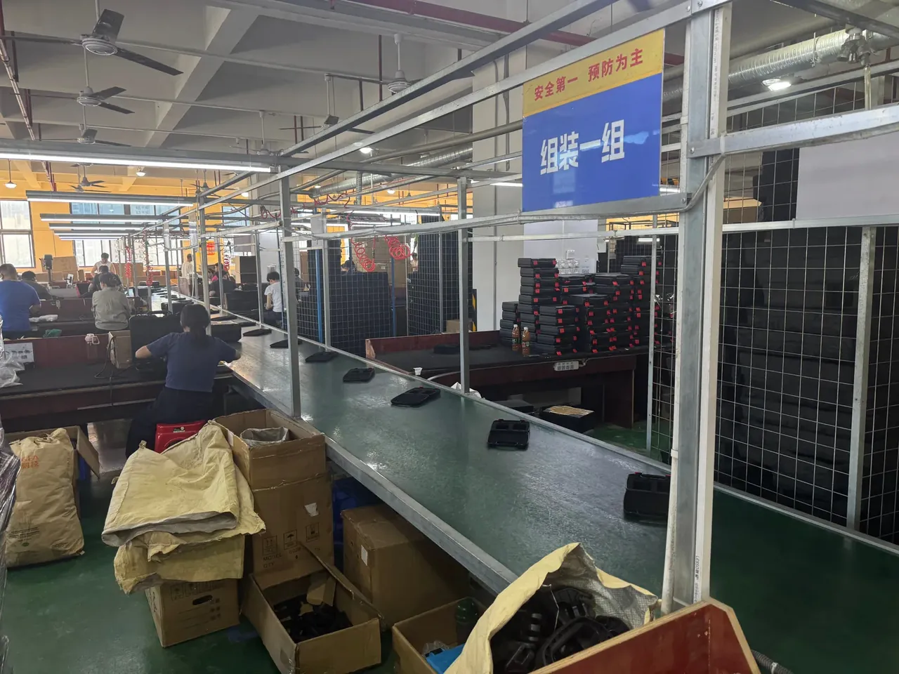
Quick answer: OEM Tooling Boundaries mark where one shared base stops: 480–640 mm width, 1.8 mm stock, 0.06 mm sink. Past that, the 220,000 CNY tool is dedicated.
Table of contents
- Size Span the Tooling Boundary Covers
- Wall Stock and Sink Depth
- Rib Thickness and Draft Angle
- Downtime When Swapping Inserts
- The Tooling Boundary Decision Table
- FAQ
1. Size Span the Tooling Boundary Covers
How wide a shell one base can frame depends on how much wall stock keeps a sink mark down. Two shared bases cover 480–640 mm of width, the largest at 640×445×255 mm outside, 575×385×195 mm inside and 4.8 mm wall. Under 480 mm takes a smaller base, over 640 mm a new frame. That ceiling is the first of the OEM Tooling Boundaries.
Shrinkage of 1.6% goes back into the cavity, so a 640 mm case cuts near 650 mm, with 0.5 mm of trim at each end. PP runs 1.0%–2.5%, so 1.6% is mid-band; change grade without recutting steel and the first lot lands small. Wider cases absorb that error badly, which ties the second OEM Tooling Boundaries figure to length.
Depth eats span too. A 195 mm cavity lengthens core stroke, so guide pins, return pins and spacers move. Fit a deeper shell and the spacer thickens until closed height hits the press minimum; width stays inside 640 mm, yet the OEM Tooling Boundaries are crossed.
| Wall stock tier | Width covered | Sink risk | Typical use |
|---|---|---|---|
| 1.2 mm | 480–540 mm | Low, flatness holds | Shallow cases, cosmetic face up |
| 1.5 mm | 540–600 mm | Medium, needs pack pressure | Cases at standard depth |
| 1.8 mm | 600–640 mm | High, ribs must divert flow | Deep cavities with boss seats |
2. Wall Stock and Sink Depth
Stock is material added beyond nominal wall. On a 4.8 mm shell, rib roots and boss seats thicken to 1.8 mm, and thick sections hold heat longer, so the face dishes. More stock means a harder dish; at 1.8 mm this base hits its ceiling, the third of the OEM Tooling Boundaries.
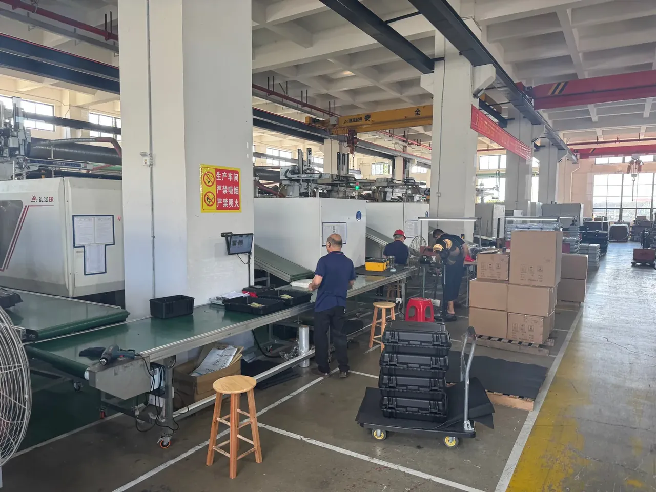
Sink depth is read on a profile projector 24 h after ejection. The release line is 0.06 mm; five parts per lot, and one over it resets pack pressure.
Pack pressure is the first lever, cooling the second. Rib roots get their own circuit; mould temperature holds near 40 ℃, since hotter moulds pack better but eject worse. When the window is narrow, drop a stock tier rather than push pressure; flatness won that way rarely survives a second pass.
3. Rib Thickness and Draft Angle
Rib thickness is 1.6 mm, one third of the 4.8 mm wall, below the usual 40%–60% band. The choice is deliberate: the closer a rib comes to wall thickness, the more its root acts as thick material and pulls a sink on the opposite face. Thin ribs buy flatness; stiffness must come from rib height, which puts the fourth OEM Tooling Boundaries value on the rib.
Rib height caps at three times the wall, or 14.4 mm; taller ribs neither fill nor cool. The root carries a 1.2 mm fillet, a quarter of wall thickness, because a sharp corner concentrates stress where a moulded shell cracks.
Draft is 1.2°, mid-band against the 0.5°–1.5° norm. Deeper ribs need more, and a textured face adds 1° per 0.025 mm of texture depth, or the flank scuffs on the way out. Set the pull wrong and 1.2° saves nothing: the OEM Tooling Boundaries fail at ejection, not on the drawing.
4. Downtime When Swapping Inserts
An insert swap keeps the base in the shop but costs 4.2 h. Split four ways: 1.1 h lifting and stripping, 0.8 h resetting water lines, ejectors and slides, 1.3 h for alignment plus first-off, 1.0 h for trial shots and records.
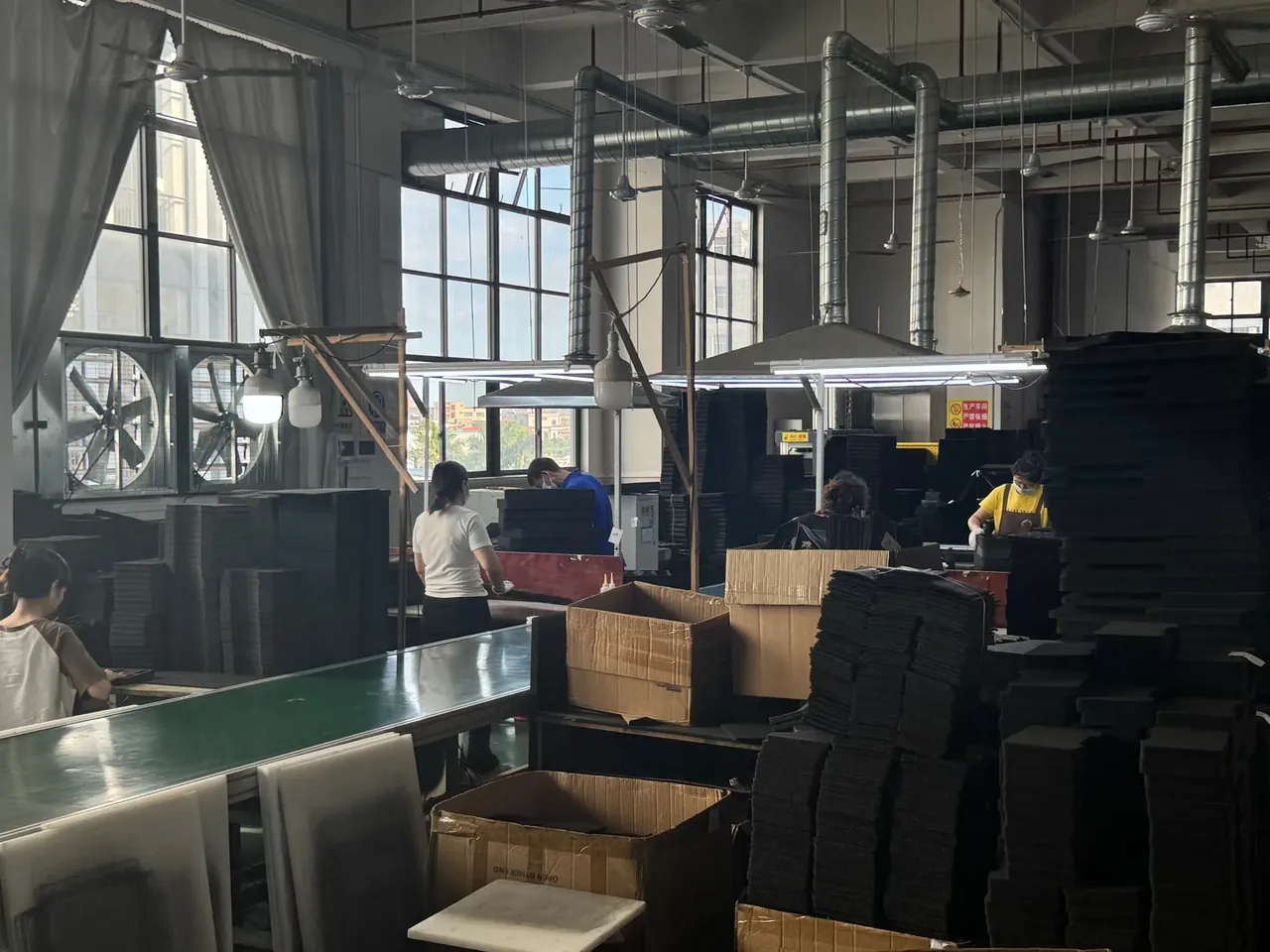
Two bases alternate: core and gate inserts change, while frame, guide pins and ejector plate stay. Because the frame never leaves the press, an insert swap does not redraw OEM Tooling Boundaries, only shifts work between bases. The insert-to-frame face keeps 0.02 mm of fitting allowance, so hand pressure will not seat it and a brass drift is needed. Overdo the drift and the face is bruised. Photograph the old insert before lifting so the new one goes back to a record. Log insert number and hour so wear shows after three models.
| Trial round | Purpose | Recorded | Pass line |
|---|---|---|---|
| First | Filling and ejection | Short-shot position, ejector marks | A complete part |
| Second | Dimensions into band | Wall, rib, three-axis outside size | Every size in tolerance |
| Third | Sink under control | Sink depth, flatness | 0.06 mm or less |
5. The Tooling Boundary Decision Table
Three lines go on one sheet: width inside 480–640 mm, stock no more than 1.8 mm, third-trial sink below 0.06 mm. Pass all three and the case stays shared; miss one and it needs a dedicated base, with a second frame outside the 220,000 CNY figure.
The stock tier is the smallest whose third-trial sink reads below 0.06 mm; any wall difference beyond that line is quoted on a dedicated base.
| Sink reading | Stock used | Flatness | Action |
|---|---|---|---|
| 0.03 mm | 1.2 mm | 0.15 mm | Release as is |
| 0.05 mm | 1.5 mm | 0.18 mm | Release after extra pack |
| 0.06 mm | 1.8 mm | 0.20 mm | Boundary, inspect each |
The verdict is not permanent: after three case models, insert wear pulls the OEM Tooling Boundaries back inward, so first-off is rechecked every 2000 shots.
Conclusion
OEM Tooling Boundaries are settled by three lines on one sheet. A shared base saves a frame and weeks spent cutting one, but never the three trial rounds. Hold the 0.06 mm sink line and the same base can take a second and a third case model.
Related Reading
- Cavity Volume and Wall Stock
- Reading Mold Bases and Inserts During an Audit
- Mold Protection in Automotive Plastics Cases
- Military Case OEM and ODM Factory
Related Products
- 8 Series — Gun Cases; Military Equipment Cases; Camera Equipment Cases; Drone Cases; Watch Cases; Knife Cases; First Aid Cases; Electronics Equipment Cases
- WL8-2812 PP Gun Case — model WL8-2812
- All protective cases and toolboxes: 7 series, 158 models