

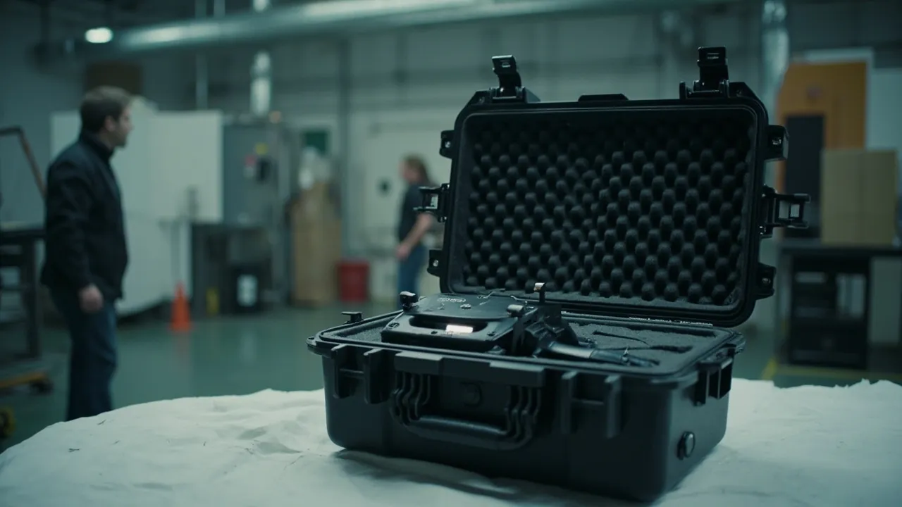
In the cost structure of automotive plastic parts, the mold and the gauge are two assets that are easy to overlook and impossible to replace quickly. A bumper or instrument-panel injection mold can be worth several hundred thousand to several million, and its development schedule is tied to the vehicle program gate. A checking fixture decides whether the part can pass dimensional approval at all. The conclusion up front: an automotive plastic parts mold case is not a box that happens to fit a mold. It is a transport protection system for tooling. Parting surfaces and cavity faces stay unloaded through profile-cut cradles and relief pockets, guide pillars and ejection systems are located independently so they cannot be knocked, and gauges are protected by unloading the datum blocks and supporting the frame over a wide area. Specify at least IP65 for the shell, go to IP67 for ocean freight and high-humidity regions, and verify the design against ISTA, GB/T 4857 and ASTM D4169 so that "it arrived" also means "it still works."
What actually keeps tooling engineers awake is not the weight of a mold but its fragility. A 0.05 mm impression on a parting surface, a chipped cavity edge, or a knock on a gauge datum block can send an entire tool back for rework, and in the worst case push a part out of dimensional tolerance so that gap and flush targets at the assembly plant are lost. This article follows the sequence of failure mode, protection design, verification method and acceptance criteria. It gives usable guidance on shell selection, insert structure, rust prevention, transport test plans and inspection checklists for tooling management teams at vehicle makers, mold shops at tier suppliers, gauge vendors, and procurement and logistics staff.
Table of Contents
- 1. Why Injection Molds and Gauges Need Dedicated Cases
- 2. Where Injection Molds Fail: Parting Surfaces, Cavities, Guides and Ejection
- 3. Gauges and Measuring Fixtures: Accuracy Tiers, Datum Protection, Distortion
- 4. IATF 16949 and PPAP: Tooling Transport Is Tooling Management
- 5. Rust and Condensation: ISO 4406 Cleanliness Awareness and VCI Limits
- 6. Edges, Cavities and Mirror Surfaces: Corners, Relief and Contact Control
- 7. Shell Structure and IP Protection: IP65/IP67, IEC 60529 and GB/T 4208
- 8. Insert Design: Profile Cradles, Layers and Load Paths
- 9. Vibration and Transport Verification: ISTA, ASTM D4169 and GB/T 4857
- 10. Temperature, Humidity and Cross-Climate Shipping
- 11. Lifting, Handling and Safe Unpacking on Site
- 12. Incoming Inspection, Traceability and AQL Sampling
- 13. Custom Insert Workflow and Selection Decision Tables
- Frequently Asked Questions
- Conclusion & Related Reading
1. Why Injection Molds and Gauges Need Dedicated Cases
To understand the value of a dedicated case, start with how automotive plastic part tooling works. An injection mold passes through design, machining, trial shots and dimensional rework over several rounds. The final state is not a lump of steel. It is a precision mating system that has already been tuned, and its value sits in the debugging hours already invested and the process state already frozen.
The transport situations for molds and gauges are more varied than most people assume.
- Mold shop to parts plant. The classic trunk route, mostly road freight, with vibration concentrated between 5 and 50 Hz. Pavement joints and speed bumps add periodic shocks.
- Intra-plant and inter-plant transfers. Molds are loaned between sites in the same group, which means repeated loading and unloading, and every load is a risk event.
- Overseas programs and export deliveries. A mold shipped with a program sees elevated container temperature and humidity, cross-climate temperature swings, salt-laden air at sea, and inland transport at the destination port.
- Gauge round trips for CMM measurement. Gauges travel between the parts plant, the vehicle maker and third-party labs. Trip frequency is high, distance is short, but handling events are numerous.
- Mold repair and maintenance. Molds return to the shop for repair, insert replacement and polishing, then go back. This is a high-frequency, short-distance pattern.
These five situations do not demand the same packaging. Long-haul cases emphasize vibration and moisture resistance. Short, frequent trips emphasize handling efficiency and reusability. Cross-ocean cases emphasize rust prevention and condensation control. The reason a generic wooden crate with bubble wrap is dangerous is that it solves exactly one problem, holding the part in place, and solves none of moisture, condensation, local edge loading or traceability.
There is also an economic argument that is routinely missed. The purchase cost of a dedicated protective case is usually under one percent of the mold value. A single transport-damage rework event involves disassembly, haulage, bench hours, trial-shot verification and possibly waiting at the customer, and its cost is typically dozens of times the case. This matches the logic set out in the custom case mold cost analysis, where front-end investment reduces total lifecycle cost.
The typical JUNZHJIA delivery format for automotive tooling protection is a combination of a profile-cut cradle and a compartmented base built around the mold outline and lifting points, with a gasketed shell and an optional pressure equalization valve, plus written structural data when the customer needs it for transport verification.
2. Where Injection Molds Fail: Parting Surfaces, Cavities, Guides and Ejection
An injection mold looks like one heavy block of steel, but the truly untouchable areas are few and concentrated. Listing them clearly defines what the insert must do.
| Location | Structural feature | Typical transport failure | Insert countermeasure |
|---|---|---|---|
| --- | --- | --- | --- |
| Parting surface (PL face) | Large precision mating face, fits often 0.02 to 0.05 mm | Impression, burr, local collapse causing flash | Never let the parting face carry load; face it away from the insert; add a rigid protective plate |
| Cavity and core | Polished or mirror finish, complex geometry | Scoring, chipping, rust spots | Profile cradle plus lint-free separator; no contact, no rubbing |
| Guide pillars and bushes | Precision mating pair, sensitive to coaxiality | Bending, galling, scored mating face | Independent relief bore for location; never use a pillar as a load path |
| Ejector pins, sleeves, plates | Slender parts, many of them | Bent or broken pins, distorted plate | Full relief cavity for the ejection system; protective sleeves on pins |
| Hot runner and nozzles | Slender heated assembly with wiring | Bent nozzle, torn thermocouple lead | Separate small compartment with soft liner; harness secured separately |
| Water fittings and cylinders | Protruding parts, first to be hit | Broken fitting, bent piston rod | Relief pocket for every protrusion; never loaded externally |
| Lifting eyes and tapped holes | Load-bearing structure, thread accuracy matters | Damaged thread, deformed eye | Protective caps on threads; store eyes separately after use |
The core rule: the weight of the mold must be carried by something other than the parting surface. The most reliable field approach is to let the mold base, meaning the feet and the base plate, sit on a high-density EVA or composite plywood frame, producing a large-area face support. The parting surface should face open space inside the case or face a soft liner, and must never be pressed against a rigid insert. A large share of workshop incidents trace back to laying the mold on its side. On its side, the full weight rests on one parting face, and with road vibration this produces an impression that cannot be recovered.
For precision pairs such as guide pillars and bushes, the correct approach is to suspend the pillar in an independent relief bore so it takes no load inside the case. Using a pillar for location is reasonable. Using it to carry weight is wrong in every case. Hot runners, cylinder rods and water fittings deserve extra attention. Their protrusion may only be a few tens of millimetres, but once loaded they bend or break, and replacing a nozzle or a piston rod is extremely labour-intensive.
For the insert material itself, the EVA foam insert custom process sets out the full workflow from density selection to CNC milling tolerance, and it can be used directly in a tooling insert technical review.
3. Gauges and Measuring Fixtures: Accuracy Tiers, Datum Protection, Distortion
Gauges follow a completely different protection logic from molds. A mold fears compression. A gauge fears distortion.
A gauge exists to provide a stable, repeatable measurement datum. Its accuracy tier is therefore far above general tooling, and it is more sensitive to structural stiffness and environmental stability. The common types and their protection priorities are as follows.
- Master checking fixtures. Large and thin-walled, usually a skeletal frame in aluminium or resin. The dominant risk is global distortion. Once the frame bends, the positional relationship among every locating pin and checking block shifts. The countermeasure is uniform multi-point support plus independent unloading of the datum blocks.
- Functional gauges and gap-flush gauges. Small and numerous, with many thin checking faces and graduated surfaces. The priority is preventing mutual impact and scoring of graduated faces.
- CMM fixtures. Made of a base plate, uprights, support rods and quick-change clamps. Uprights are slender and lateral vibration bends them easily; the base plate is the master datum and loses its value the moment it is dinged.
- Stamping and weld-assembly gauges. Often fitted with toggle clamps and flip mechanisms. If they are not locked reliably before packing, they swing inside the case and strike other parts.
- Portable measuring stands and surface plates.
Three actions are decisive when packing a gauge.
- Unload the datum blocks separately. Datum planes and datum holes are the origin of the gauge. Load must be transferred from the datum region straight into the base through blocks or support posts, and the accuracy faces must not carry weight.
- Lock every moving element and add secondary restraint. Clamps, flip arms and sliding mechanisms must be locked before packing, with auxiliary supports inside the case to stop reciprocating swing in transit.
- Support slender uprights axially to prevent bending. Uprights must be supported in groups with mid-span support, never left as free cantilevers.
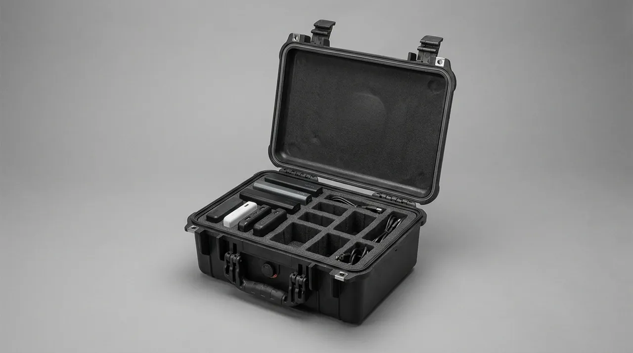
For which insert material carries load and which absorbs shock, the case foam material comparison benchmarks EVA, EPE, PU and XPE for resilience, compression set and load capacity, and it is a useful reference for gauge insert selection. The usual JUNZHJIA approach on gauge cases is a two-layer build: a rigid frame that carries load plus a soft facing that protects the accuracy surfaces.
4. IATF 16949 and PPAP: Tooling Transport Is Tooling Management
For suppliers in the automotive chain, tooling and gauges are not ordinary material. They are controlled assets inside the quality system.
The basic position of IATF 16949 is that the design, manufacture, acceptance, use, maintenance and storage of tooling and gauges must all be controlled. What a layperson hears as a vague phrase about storage, an auditor reads as a document set: a tooling register with identification, storage and handling requirements, maintenance records and an abnormality process. Packaging, as part of handling and storage control, should therefore be defined explicitly.
PPAP ties tooling status directly to part approval. A PPAP submission package normally has to state the current status of the tooling, whether it is used in production, and how tooling and gauges are identified and traced. If a mold or gauge is damaged in transit, then even after repair it may need dimensional capability re-verification, which can affect the PPAP conclusion. That is the practical basis for saying transport protection belongs inside the quality system.
Expressed in system language, transport protection for molds and gauges should include at least the following records.
| Record | Content | Purpose |
|---|---|---|
| --- | --- | --- |
| Tooling register | Mold number, gauge number, revision, applicable part number | Traceability and mis-load prevention |
| Packaging plan drawing | Case model, insert structure, packing orientation, lifting points | Work instruction for the shop floor |
| Packing checklist | Cleaning, rust prevention, locking, fastening, sealing, desiccant | Pre-shipment confirmation |
| Transport test report | ISTA, ASTM D4169 or GB/T 4857 records | Customer audit evidence |
| Unpacking checklist | Appearance, rust, distortion, damage records and photos | Responsibility allocation and claims |
| Storage and environment log | Location, temperature and humidity, stack height, storage duration | Long-term storage compliance |
A practical recommendation: make the packaging plan drawing part of the tooling acceptance file. When a mold passes acceptance, confirm and archive its packaging plan at the same time, and execute every subsequent transfer to that same plan. This stops the shop floor from improvising and makes responsibility boundaries much clearer.
Note that IATF 16949 and PPAP are system and process requirements. They do not specify packaging technical parameters. IP rating, insert density and cushion thickness still have to be determined independently from IEC 60529, GB/T 4208, the ISTA series and the GB/T 4857 series.
5. Rust and Condensation: ISO 4406 Cleanliness Awareness and VCI Limits
Rust on a mold is more insidious than a knock and often more expensive. Once rust appears on a parting surface or in a cavity, the tool has to be polished, and polishing changes cavity dimensions, which triggers a new trial shot.
The first principle of rust prevention is controlling humidity, not applying grease.
Three preconditions must be met before a mold is packed: it must be clean, completely dry, and free of surface contamination. Residual cutting fluid, release agent and hand sweat are all moisture sources and corrosion sources, and they create local electrochemical cells on tool steel and stainless steel. The industry often cites ISO 4406 particle contamination classes when stating cleanliness requirements, a standard that expresses the number of particles in different size bands per unit volume. In the mold and gauge world it is best understood as a cleanliness discipline: no visible particles, oil or metal chips should remain, especially on parting surfaces and sliding fits. The actual acceptance limit should be agreed between buyer and supplier in the technical agreement.
Usable combinations of rust and condensation countermeasures include the following.
- Dedicated protective agents for parting surfaces and cavities. Use rust-preventive grease or a dry rust-preventive film that is compatible with later production, and avoid heavy oils that leave oil marks on the first shot.
- The limits of vapour corrosion inhibitor, or VCI. VCI works well on carbon and tool steels but carries risk for copper, brass, zinc and some aluminium alloys. Molds with copper inserts, beryllium copper or zinc-plated parts must have compatibility confirmed first. VCI is not a universal solution, and the wrong formulation accelerates discoloration.
- Desiccant sizing. Estimate from free space volume inside the case and the transport duration. A practical rule is 1 to 2 kg of high-efficiency desiccant per cubic metre of free space, doubled for long ocean voyages, with a humidity indicator card placed somewhere visible on opening.
- Sealing and pressure equalization. A fully sealed case develops a pressure differential as temperature changes, which can deform the gasket or make the case hard to open. A case with a pressure equalization valve balances the differential while keeping the IP rating, and the mechanism is explained in case pressure equalization valve.
- Metal and seal compatibility. Gasket material must be compatible with the rust preventive and cleaning agents, or it will swell, harden or crack. The relevant material boundaries are collected in seal material and case compatibility.
A field experience value: in a sealed case at normal ambient temperature with a suitable amount of desiccant, mold surface protection can typically hold for 6 to 12 months. For ocean-freight export programs, inspect and re-apply protection immediately on arrival at the destination.
6. Edges, Cavities and Mirror Surfaces: Corners, Relief and Contact Control
A large share of mold and gauge damage happens at edges and cavity faces, because those are the geometric features that concentrate stress or make direct contact.
Edge protection has three layers.
The first is geometric relief. Right-angle edges, fillets, bosses and steps on a mold need matching clearance in the insert. In practice, design the insert cavity 1 to 3 mm outside the actual mold outline so an edge cannot press on the insert and create a point load.
The second is corner and edge guards. For exposed sharp edges, soft corner guards inside the case, or a rigid protective plate, let the impact be taken and spread by the guard first.
The third is contact surface control. The worst arrangements are hard against hard and two-point contact. Hard against hard produces fretting wear under vibration. Two-point contact concentrates the whole load at two points and leaves local impressions.
Additional requirements for cavity and mirror surfaces.
- A cavity face should never contact another object directly. The workable arrangement is to orient the cavity upward or inward, or toward a soft liner, and to separate it with lint-free cloth or PE film.
- If the mold geometry forces the cavity to face downward, for example some deep-cavity designs, the insert must include a full matching cavity so the cavity rim lands on a soft facing rather than a rigid support.
- Mirror-finish molds, such as those for clear or high-gloss parts, should get an additional lint-free separator film to prevent fretting against the insert.
Protecting measuring and graduated faces. Checking blocks, scales and master spheres on a gauge should sit in separate soft compartments with a dust cover, so that dust cannot settle on measuring faces and affect accuracy.

7. Shell Structure and IP Protection: IP65/IP67, IEC 60529 and GB/T 4208
The shell is the outer layer of the protection system. Its job is to keep environmental loads outside while providing a stiff, reusable platform for carrying load.
IP ratings are defined by IEC 60529 and, in China, by GB/T 4208, which use consistent classification methods and acceptance criteria. For mold cases the common grades mean the following.
| Rating | Dust | Water | Practical meaning for a mold case | Typical use |
|---|---|---|---|---|
| --- | --- | --- | --- | --- |
| IP54 | Dust protected | Splash resistant | Basic dust protection, workable for short in-plant trips | Short in-plant moves, dry shops |
| IP65 | Dust tight | Water jets | Resists washdown and rain, strong value | Trunk road freight, normal warehousing |
| IP66 | Dust tight | Powerful water jets | Withstands high-pressure water streams | Open-air storage, frequent cleaning |
| IP67 | Dust tight | Temporary immersion, typically 1 m for 30 min | Tolerates short immersion and standing water | Ocean export, high-humidity and rainy regions |
Two points are commonly misread. First, IP67 does not mean the case can stay submerged long term; the standard defines temporary immersion. Second, an IP rating describes only the shell's resistance to solid foreign objects and water. It says nothing about impact, crush or theft resistance. Do not use IP as a strength indicator.
On material, engineering plastic shells do not rust, resist chemical attack, can be washed repeatedly and weigh less than steel. Metal shells are stronger in extreme load and puncture, but their own corrosion and the way inserts are fixed must be considered. For automotive tooling, most molds weigh from a few hundred kilograms to several tonnes. At that point the sensible options are a steel base pallet with a plastic hood, or a heavy-duty engineering plastic case with forklift pockets, rather than insisting on an all-plastic build.
The hidden risk in hardware. Hinges, latches and gaskets are the life-limiting parts of any case. Poor latches work loose under vibration, hinge pins wear, and gaskets age. The selection points and failure modes for these three component groups are covered systematically in toolbox hinge latch and seal structure, which can be used directly in supplier reviews. In addition, where a case must enter an interior-parts shop or a finished-goods store at a vehicle plant, some customers impose a flame-retardancy requirement on the plastic case material. UL94 is the common evaluation method for plastic burning behaviour, with typical classes such as V-0, V-1, V-2 and HB, and the required class and test method should be written into the technical agreement to avoid disputes at acceptance. JUNZHJIA can fit reinforced hinges, metal latches and replaceable gaskets sized to the mold weight and the lifting method, can confirm flame-retardancy class requirements with the customer, and supplies the structural parameters in writing.
8. Insert Design: Profile Cradles, Layers and Load Paths
The insert is the body of the protection system. The shell decides whether the case survives external force. The insert decides whether the part experiences force at all.
Designing an insert for a mold or gauge means designing a clear load path: weight goes from the mold's own load-bearing faces to the insert support faces, into the base frame, into the case floor and finally to the forklift or lifting points. At no point on that path should it pass through an accuracy surface.
Insert structures and their applications.
| Insert structure | How it is built | Advantages | Typical use |
|---|---|---|---|
| --- | --- | --- | --- |
| Full profile cradle | CNC-milled EVA or PU forming a cavity that matches the mold outline | Large contact area, high locating accuracy | High-value injection molds, mirror-finish molds |
| Rigid frame plus soft facing | Plywood or engineering plastic frame carries load, EVA or lint-free cloth bonded on top | High stiffness, handles heavy loads | Large molds, gauge base plates |
| Layered build | High-density bottom for load, profile layer for location, top layer for compression | Balances load capacity and protection | Multi-part cases with accessories |
| Compartmented layout | Independent pocket per part, each located separately | Prevents mutual impact, easy counting | Ejector pins, inserts, small gauges |
| Adjustable dividers | Divider positions can move or be removed | Low changeover cost, suits many batches | Mixed loads, frequent batch changes |
Design checklist.
- Pick the load-bearing face on the mold base or feet, never on the parting surface, cavity face or guide components.
- Relieve every protrusion. Cylinders, water fittings, lifting eyes, ejector rods and terminal blocks all need their own clearance.
- Control compression. For soft inserts, keep compression between roughly 10 and 20 percent of material thickness. Too much compression means no cushioning; too little means the part is not held.
- Provide a compression face in the lid. When the case closes, the insert should lightly press the part and remove any freedom to jump. Compression must be even, never forced at one point.
- Design for reuse. The insert must survive repeated load and unload cycles without collapsing, so choose materials with low compression set.
- Prevent foreign matter. Milling debris must be completely removed, otherwise it becomes an abrasive.
Where several tooling variants and frequent batch changes are involved, the approach in the removable divider system lets one case serve several tools with adjustable dividers, which cuts changeover packaging cost significantly.
9. Vibration and Transport Verification: ISTA, ASTM D4169 and GB/T 4857
A finished design is not a proven design. Three families of standards dominate automotive tooling transport verification.
- The ISTA series covers performance test procedures for transport packaging, grouped by transport mode and package type. ISTA 3A applies to parcel delivery, ISTA 3E to unitized loads, and ISTA 2A to the simulated performance of individual packages. For heavy cases such as mold boxes, ISTA 3E and 3B provide the usual frame of reference. The procedure selection logic is described in the ISTA transport testing procedure.
- ASTM D4169 uses a distribution cycle framework, combining test sequences by transport stage and risk level, which suits multimodal export programs involving road, rail and sea. The sequence logic is set out in the ASTM D4169 distribution cycle case.
- The GB/T 4857 series is the Chinese family of basic test methods for transport packages, covering vibration, impact, drop, stacking and compression. Domestic supply and domestic transfer programs normally rely on this series, consistent with the methods in GB/T 4857 transport packaging verification.
For a mold case, the test set can be trimmed along the following lines.
| Test | Purpose | Key observation for a mold case |
|---|---|---|
| --- | --- | --- |
| Random vibration | Simulates sustained road and rail vibration | Fastener loosening, insert migration, fretting at edges |
| Drop and impact | Simulates handling impacts | Shell cracking, insert penetration, part migration |
| Stacking and compression | Simulates warehouse and container stacking | Shell distortion, loss of internal clearance |
| Fixed-frequency vibration | Screens for resonance risk | Sustained vibration near a part's natural frequency |
| Concentrated impact | Simulates forklift or foreign-object strikes | Local puncture and crush resistance |
| Temperature and humidity cycling | Simulates cross-climate and container conditions | Condensation, corrosion, gasket performance, insert dimensional stability |
A pragmatic recommendation: run random vibration plus drop first. They cost the least and reveal the most. If fasteners loosen or the insert migrates, improve the insert structure and the fastening method rather than simply thickening the walls.
Test reports should record the actual condition of the test item, including the mold or the equivalent mass dummy, the test parameters and the observations. When an equivalent rigid mass is substituted for a real mold, the substitution must be stated, otherwise the credibility of the report will be challenged by the customer.
10. Temperature, Humidity and Cross-Climate Shipping
Cross-climate shipping is the biggest hidden risk in mold export programs. A mold sits in a dry workshop at the point of manufacture, then goes into a container that may cycle through 60 degrees Celsius by day and 15 degrees Celsius at night, with relative humidity inside the case above 90 percent for extended periods. That is textbook condensation.
MIL-STD-810H is often used as the methodological basis for environmental testing, defining procedures and tailoring methods for temperature, humidity, vibration, shock and salt fog. The correct way to use it is to select the appropriate method and procedure, tailor them to the actual transport and use environment, and produce a program-specific test profile. It must be stated clearly that MIL-STD-810H is an environmental test method standard, and using it does not mean a product has obtained any military certification. No such implication should appear in customer communication or product literature.
Specific measures for mold cases.
- Temperature and humidity cycling. Use a hot-humid, cool-down, cold and warm-up cycle profile to check whether condensation forms inside the case and whether the gasket retains elasticity at low temperature.
- Salt fog. For ocean export and coastal plant programs, salt fog methods help assess the effectiveness of protection on case hardware and mold surfaces. Salt fog is an accelerated test, and results must be interpreted with the real situation in mind.
- Low pressure. High-altitude road transport and air freight create low pressure, which worsens the differential across a sealed case and raises the value of a pressure equalization valve.
- Thermal shock. Loading a truck in a cold-region winter or leaving a case in direct sun in a hot climate both create steep temperature gradients and put insert dimensional stability under test.
Three low-cost measures that work in practice.
- Place adequate desiccant plus a humidity indicator card inside, so the reading at unpacking becomes acceptance evidence.
- Apply a dry rust-preventive treatment to mold surfaces so large-scale corrosion does not develop at sea.
- Use a sealed case with a pressure equalization valve to reduce gasket fatigue from temperature swings.
For material and structural behaviour at temperature extremes, extreme temperature case summarizes common boundaries for low-temperature embrittlement and high-temperature softening in engineering plastics, and it can be used as a selection reference.

11. Lifting, Handling and Safe Unpacking on Site
Half of the safety problem with mold cases is in transport, and half is in handling. A multi-tonne case that gets away from the crew does far more damage than a damaged mold.
Lifting and handling points.
- Mark the centre of gravity and the lifting points. The case should carry clear markings for both, and the lifting points must be structurally verified. Control the sling angle within a reasonable range so an excessive angle does not overload the points.
- Prefer forklift pockets to slings. For heavy mold cases, forklift pockets at the base are the safest handling interface and reduce the risk of sling slip.
- Never lift by a protrusion. This is the most common accident cause: a sling is thrown over a water fitting or a cylinder for convenience.
- Limit stack height. Mold cases are heavy-duty items. Stacking must follow case capacity and contents weight, and the limit must appear both on the case and in the documents.
- Watch floors and ramps. Forklift transport must respect floor flatness and slope limits to avoid tip-over.
- Stabilize before opening. Before releasing latches, confirm the case is in a stable position. Where the hinge side is up, watch for lid rebound.
Immediate actions after unpacking, ideally written into a work instruction.
- Photograph the case exterior and seal condition.
- Read and record the humidity indicator card as soon as the case is open.
- Check the mold surface for rust, unusual stains and impact marks.
- Check whether fasteners and locking mechanisms loosened in transit.
- Check the insert for collapse, migration and damage.
- Complete and sign the unpacking checklist.
The value here is responsibility allocation. If damage is found on arrival, the unpacking checklist and photos support a claim against the carrier or supplier. If feedback is delayed by days, defining responsibility becomes very difficult.
12. Incoming Inspection, Traceability and AQL Sampling
A mold case is itself a purchased item and should be accepted by batch.
A three-layer inspection structure works well.
Layer one, appearance and structure. No cracks, no abnormal distortion, no sharp burrs. Hinges and latches move freely and lock reliably. The gasket shows no obvious gap or compression set. Handles and casters, if fitted, are secure.
Layer two, function and performance. Sealing performance is sampled against the declared IP rating using the acceptance methods of IEC 60529 and GB/T 4208. Insert dimensions match the drawing and the cavity fits the part. Stacking stability and forklift pocket dimensions meet the requirement.
Layer three, documents and marking. Factory inspection records, material declaration, structural parameter statement, packing list and marking content are complete.
AQL sampling can borrow the established framework used in consumer goods inspection: determine sample size from batch quantity and judge by defect class. For an industrial item such as a mold case, shell cracking, sealing failure and hinge detachment should be classed as critical defects that are not permitted, while cosmetic scratches, unclear marking and local insert burrs are minor defects permitted within limits. The full classification method is described in custom case acceptance and AQL.
Marking and traceability are hard requirements in tooling management. A case should carry at least the following.
| Marking | Suggested content | Form |
|---|---|---|
| --- | --- | --- |
| Tooling number | Mold or gauge number plus revision | Durable label or laser marking |
| Contents | Part name and applicable vehicle program | Label |
| Weight and centre of gravity | Gross weight, net weight, CG position | Screen print or label |
| Stacking and lifting | Permitted stack layers, lifting point positions | Screen print graphic |
| Protection rating | IP rating and temperature range | Screen print or label |
| QR code | Link to the electronic file with packing drawing and records | Weather-resistant label |
For molds kept in long-term storage, add a desiccant replacement record card inside the case and an environmental recording label on the shell, so a periodic check can quickly show whether moisture exposure has occurred.
13. Custom Insert Workflow and Selection Decision Tables
A standard custom insert workflow that can serve directly as a supplier technical requirement.
- Information review. Provide a 3D model of the mold or gauge in STEP or IGES, or complete 2D drawings, plus weight, centre of gravity, lifting points and a list of protrusions.
- Concept design. Select the case model and insert structure and issue the insert layout and packing orientation drawings.
- First-article trial fit. Build the first insert and check relief clearances, even compression and ease of loading.
- Adjust and freeze. Fine-tune cavity dimensions and compression from the trial feedback, then freeze the drawing revision.
- Production and factory inspection. Sample dimensions and appearance by batch and supply inspection records with each case.
- Change management. When a mold or gauge is revised, the insert drawing is revised in step and the old revision is withdrawn.
For the wider collaboration boundary from requirement to volume production, how to choose a case OEM factory lists the core dimensions for assessing a supplier, including mold capability, insert machining accuracy, inspection equipment and document completeness. JUNZHJIA provides an integrated service from 3D model interpretation and insert concept design to volume supply and OEM or ODM branding, and can issue structural parameters and inspection documents on request.
Selection decision table.
| Situation | Recommended shell | Recommended insert | Priority verification |
|---|---|---|---|
| --- | --- | --- | --- |
| Short in-plant moves, under 50 km | IP54 to IP65 engineering plastic case | Compartmented location with soft facing | Handling efficiency, stacking stability |
| Domestic trunk road freight | IP65 reinforced case with forklift pockets | Profile cradle plus rigid frame | Random vibration, drop |
| Ocean export across climate zones | IP67 with pressure equalization valve | Full profile plus desiccant and rust barrier | Temperature and humidity cycling, salt fog, stacking |
| Gauge round trips for measurement | IP65 small to mid-size case | Rigid frame with datum unloading | Drop, insert stiffness |
| High-value mirror-finish mold | IP67 heavy-duty case | Full profile, lint-free separator, compression face | Random vibration, contact surface inspection |
| Mixed batches of inserts | IP65 standard case | Adjustable dividers plus compartment boxes | Counting convenience, mis-load risk |
Common misconceptions.
- Misconception one: thicker walls mean safer. Thickness only addresses external crush, not internal loading.
- Misconception two: fill it with foam and it is fine. Uncontrolled compression lets the part migrate under vibration.
- Misconception three: the mold is heavy, so vibration is not a concern. The opposite is true, since greater mass means greater inertial load.
- Misconception four: IP67 means long-term submersion. The definition is temporary immersion and cannot be extrapolated.
- Misconception five: one test result lasts forever. Tooling revisions, route changes and case ageing all invalidate the conclusion.
Frequently Asked Questions
Q: What are the most common damage types in automotive injection mold transport, and how can each be prevented? A: Field data typically concentrates damage into four groups. The first is impression and burr on the parting surface, caused mostly by laying the mold on its side or letting the parting surface carry load; prevent it by making the mold feet or base plate carry all the weight, orienting the parting surface toward open space and adding a rigid protective plate. The second is scoring of cavities and mirror surfaces, usually from milling debris left in the insert or from fretting against a hard surface; prevent it by removing debris completely, using a lint-free separator film and providing full profile support. The third is bending or breaking of slender protrusions such as guide pillars, ejector pins and water fittings, caused by external loading on those parts; prevent it with an independent relief cavity for every protrusion and by never using a protrusion as a support point. The fourth is corrosion, most often in ocean freight or long storage; the core measures are cleaning and drying, a rust-preventive treatment, adequate desiccant, a sealed shell and a humidity indicator card inside. Each damage type maps to one design action, and skipping any one of them leaves a hidden risk.
Q: What is the essential design difference between a gauge case and a mold case? A: The difference is what each one fears. A mold fears local pressure and impact, because its parting and cavity faces are precision mating surfaces that must be re-fitted once impressed. A gauge fears global distortion and datum loss, because its purpose is to provide a stable measurement datum; if the frame bends or twists, the relative positions of every locating pin and checking block shift and the gauge loses its meaning. A mold case therefore focuses on relief and load-bearing face selection, steering weight away from accuracy faces. A gauge case focuses on stiffness and datum unloading, using uniform multi-point support and independent locating blocks to transfer load from the datum region straight into the base, so accuracy faces never carry load. Gauges also commonly carry toggle clamps and flip mechanisms, which must be locked and given secondary restraint before packing to prevent swing. Understanding this difference is the precondition for choosing the right insert structure.
Q: How should IP65 and IP67 be chosen, and is a higher rating always better? A: Higher is not always better. Match the rating to the situation. IP65 means dust tight and resistant to water jets; IP67 means dust tight and able to withstand temporary immersion, typically 1 metre for 30 minutes. For short in-plant moves and ordinary dry warehousing, IP65 is sufficient, and paying more buys no real protection benefit. IP67 is genuinely needed in three situations: ocean export and cross-climate shipping, where containers develop condensation and local standing water; regions with heavy rainfall or sustained high humidity; and sites where open-air storage or yard flooding is possible. Choosing a higher rating carries three consequences. Better sealing means poorer ventilation, so moisture accumulates more readily and desiccant plus a pressure equalization valve become necessary. Gaskets harden at low temperature and lose resilience, so cold-region programs must confirm low-temperature gasket performance. Higher ratings usually mean greater opening resistance, which matters where parts are picked frequently. Define the situation first, then the rating, rather than chasing the highest number.
Q: What happens if a mold is packed without any cleaning? A: The consequences are usually more serious than expected. Cutting fluid, release agent, oil and hand sweat left on a mold after machining and trial shots are themselves moisture and corrosion sources. Most cutting fluids are water-based, so residue in parting surface gaps keeps local humidity high and creates a microenvironment for electrochemical corrosion. Release agents and oil attract dust and metal chips, forming abrasive particles that produce fretting wear on parting surfaces and sliding fits under transport vibration. Chlorides in hand sweat are unfavourable to tool steel and encourage pitting. Oil also masks existing minor damage, so the problem is only discovered on arrival, when responsibility is hard to establish. The correct sequence is to clean first with a cleaner compatible with tool steel, dry completely with particular attention to deep cavities and blind holes, apply a rust-preventive treatment, and then pack. Incomplete drying is the step most often skipped, and water left in deep holes or cavities keeps humidity high inside a sealed case and can produce rust spots on tool steel within weeks.
Q: How much desiccant should go inside the case, and is there a usable estimation method? A: The practical field method is based on free space volume inside the case. For normal situations, allow 1 to 2 kg of high-efficiency desiccant per cubic metre of free space; double it for long ocean voyages of 30 days or more, and add a further margin for cross-climate transport. Free space means the net volume inside the case after subtracting the mold and the actual insert, not the external case dimensions, and this is a common calculation error. Beyond quantity, three points matter. First, desiccant must sit where air can circulate; packed under the mold or pushed into the farthest corner, its absorption efficiency drops sharply. Second, the sealing rating of the shell directly determines how fast desiccant is consumed, so a large amount of desiccant in an IP54 case performs far worse than a moderate amount in an IP67 case. Third, a humidity indicator card should always be used, placed where it can be read on opening, to provide quantitative acceptance evidence. If the card has changed colour, the desiccant is saturated; re-apply rust protection and replace the desiccant rather than releasing the tool to production.
Q: What additional transport testing does an ocean export program require? A: Compared with domestic transfers, ocean export adds at least three tests and three measures. On testing: first, temperature and humidity cycling, to verify whether condensation forms inside during repeated hot-day and cool-night cycles and whether the gasket retains resilience at low temperature; second, salt fog assessment, to judge how effective protection on case hardware and mold surfaces is in the salt-laden atmosphere of sea freight, remembering that salt fog is accelerated and results need careful interpretation; third, stacking and compression testing, since container stacking is normal and the effect of stack height and sustained pressure on insert compression and shell distortion must be evaluated. On measures: first, use a sealed case with a pressure equalization valve so temperature-driven differentials do not fatigue the gasket; second, use a dry rust-preventive treatment rather than heavy oil, to avoid difficult cleaning and oil marks on first shots at the destination; third, inspect immediately on arrival and re-apply protection as needed. Export programs should also mark cases bilingually and ship the packing drawing and inspection records with the case.
Q: What is the workflow and lead time for a custom mold case insert, and what information is needed? A: The standard workflow has six steps: information review, concept design, first-article trial fit, adjustment and freeze, volume production, and change management. The core information required includes a 3D model of the mold or gauge in STEP or IGES format, which is easiest for reading the outline directly, or complete 2D drawings with key fit dimensions; the net weight and centre of gravity; a complete list of lifting points, lifting eyes and protrusions such as cylinders, water fittings, hot runners, air cylinders and terminal boxes; the opening direction and required packing orientation; the intended transport mode, single-trip distance and whether ocean freight is involved; and whether several tools must share one case. The more complete the input, the higher the chance the concept passes first time. The trial fit step is critical because it exposes problems invisible at the design stage, such as insufficient relief for a protrusion, a loading gap that is too narrow, or uneven compression. Once the trial fit passes, freeze the drawing revision and move to volume production. If the mold is later revised, the insert drawing must be revised in step and the old revision withdrawn to prevent shop-floor errors.
Q: What should be considered when mold cases are kept in long-term storage? A: The main long-term risks are slow moisture ingress and insert ageing, so management priorities differ from the transport phase. First, choose a storage location that is shaded, ventilated, thermally stable and not affected by rising damp from the floor; avoid placing cases against external walls or directly on the ground, and use a pallet underneath. Second, for sealed cases, check the humidity indicator card periodically and replace desiccant according to the record card, typically every three to six months, and more frequently for storage spanning a year. Third, avoid long-term stacking under heavy load, since sustained pressure on an insert causes compression set and the insert then fails to hold the part; respect the permitted stack height and rotate stacks periodically. Fourth, keep inserts out of prolonged high temperature and direct sunlight, which accelerate ageing. Fifth, establish a discipline of moving parts into the warehouse on arrival with periodic inspection, and record the results. For molds unused for more than a year, confirm cavity condition and the freedom of sliding elements before they return to the line. Following these points typically keeps storage-related losses low.
Conclusion & Related Reading
Protecting automotive plastic part molds and gauges in transit is fundamentally an engineering problem of steering load away from accuracy surfaces. Four statements summarize the article. First, the vulnerable points are concentrated on parting surfaces, cavity faces, guide components, datum blocks and slender protrusions, and the insert must relieve each one and keep it at zero load. Second, weight must be carried by the mold feet or base plate through a profile cradle or rigid frame that creates a large-area face support, and point loading and side storage must never be allowed. Third, rust prevention is a combination of clean, dry, sealed and desiccated, with the IP rating matched to the situation, and IP67 with a pressure equalization valve recommended for ocean export. Fourth, effectiveness must be proven by transport testing under ISTA, ASTM D4169 and GB/T 4857, and the process and records must be formalized in the language of IATF 16949 and PPAP.
Written down, these actions become an executable packaging plan: case model and IP rating, insert structure and relief list, packing orientation and lifting points, rust prevention and desiccant configuration, verification test items, marking and traceability content, and the unpacking checklist. JUNZHJIA can provide profile-cut insert customization built around the actual mold and gauge outlines, case OEM and ODM supply, and structural parameter and inspection document support, helping automotive supply chain organizations turn tooling transport from a shop-floor judgement call into a controlled process.
Related Reading