

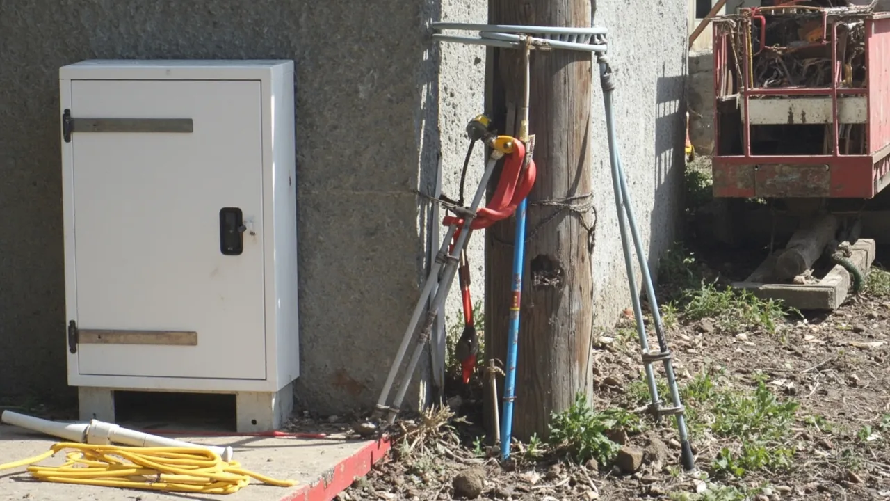
Let me start with something slightly unpopular: when an outdoor waterproof box is installed badly, it is usually not because the tools were inadequate but because the sequence was wrong. The classic version goes like this: the box gets bolted to the wall first, and only then does someone remember that cables have to enter through the bottom. At that point a drill cannot reach, so the hole goes in the side - and the whole waterproof design is dead from step one.
Tools matter, but their job is to execute a correct sequence. This article follows the real order of work: what to decide before you start, a tiered tool list, then the seven steps of positioning, drilling, gland fitting, mounting, wiring, closing up, and checking, followed by eight frequent mistakes and the differences between wall types. Figures are general industry practice and common specifications; always defer to the product manual and local code for actual values.
On safety, up front: any work on live circuits, at height, or in wet conditions should be carried out by a qualified electrician in accordance with local electrical regulations. This article addresses installation and preparation in the de-energised state and does not replace local rules or professional judgement.
Contents
- Three Decisions Before You Start
- Tool List: Essential, Recommended, Optional
- Drilling: Three Methods Compared
- Tool Budget and Selection Advice
- Step One: Siting and Marking Out
- Step Two: Drilling and Deburring
- Step Three: Fitting Glands and Plugging Spare Openings
- Step Four: Four Ways to Fix the Enclosure
- Step Five: Wiring and Termination
- Step Six: Sealing, Closing and Tightening Sequence
- Step Seven: Six Checks Before Energising
- Eight Frequent Installation Mistakes
- Fixing by Substrate Type and Maintenance Tools
- Frequently Asked Questions (FAQ)
- Closing Thoughts and Further Reading
Three Decisions Before You Start
Where the box goes. Three principles: bottom entry, clear of standing water, and accessible for maintenance. Bottom entry is non-negotiable, because gravity is the most reliable ally waterproofing has. Clear of standing water means not directly under a roof edge, not in a low spot, and not in the discharge path of air-conditioning condensate. Accessible means at least 600 mm of working space in front and a door that opens past 90 degrees.
Mounting height is typically 1.2 to 1.5 m from the ground to the bottom of the box on walkways and equipment strips, rising above 1.8 m where children might reach. Pole mounting commonly sits at 2.5 to 3 m, subject to local rules.
Where cables enter. Before touching a tool, draw out the route of every cable: which direction it arrives from, its outside diameter, how many holes are needed. A practical rule is 20% spare capacity - one or two more openings than you need today, each fitted with a plug. Adding a cable later without drilling again is an enormous convenience.
What goes inside. Terminal blocks, breakers, power supplies, fibre termination boxes: each has its own mounting method - DIN rail, back plate, or sub-panel - and its own heat output. Heat decides whether you need a vent or louvres, and any louvre must be at the bottom with an insect screen. Volume decides box size, and equipment should occupy no more than 60% of the base area so there is room for wiring and airflow.
Two further points belong in this early planning stage, because neither can be corrected once the box is on the wall. The first is sun exposure. A dark enclosure on a sun-facing wall in a hot climate can reach 70 to 80 C internally, enough to shorten the life of power supplies and soften some cable sheaths. Where there is a choice, prefer a shaded wall or fit a sun shield, and remember that plastics lose stiffness as they heat, so a hot site also argues for closer latch spacing and a more heat-resistant enclosure material. The second is access for future work. Ask who will open this box in three years, what they will need to reach, and whether a step ladder or a service vehicle will be involved. A box mounted where the door cannot swing open, or where a technician cannot see inside while working, is a box that will be maintained badly - and poor maintenance undoes good installation faster than any other factor.
Tool List: Essential, Recommended, Optional
Split three ways: cannot work without it, makes the job much faster and more reliable, and needed only for professional or special cases.
Essential:
| Tool | Suggested specification | Purpose |
|---|---|---|
| --- | --- | --- |
| Tape measure | 3-5 m | Positioning, measuring holes and cable diameters |
| Spirit level | 600 mm, magnetic preferred | Box level; prevents door drop |
| Marker or scriber | Fine tip | Marking hole centres |
| Electric drill | 500-800 W, variable speed | Drilling, driving screws |
| Step drill or hole saw | 16-32 mm step bit; or 20/25/32 mm hole saw | Bottom entry holes |
| Deburring tool or round file | General | Chamfer and de-burr holes |
| Insulated screwdrivers | VDE 1000 V, flat and cross | Terminal tightening |
| Wire stripper | 0.5-6 mm² | Strip without nicking conductors |
| Crimping pliers | For 0.5-6 mm² terminals | Fitting bootlace ferrules |
| Torque screwdriver | 1-6 N·m | Lid bolts to specified torque |
| Adjustable or open-end spanner | To suit gland flats | Tightening cable glands |
| Multimeter | Continuity, resistance, voltage | Verification and rough insulation check |
| Voltage tester, contact or non-contact | 12-1000 V | Confirming dead |
Recommended, because they raise speed and reliability substantially:
| Tool | Suggested specification | Why |
|---|---|---|
| --- | --- | --- |
| Hammer drill plus masonry bits | 6, 8, 10 mm | Essential on brick and concrete |
| Expansion anchors | M6 or M8 in 304 stainless | Far more reliable than plastic plugs |
| Stainless pole band clamps | To suit pole diameter, with rubber liner | Pole mounting; liner grips and isolates |
| Ratchet screwdriver set | Multi-bit | Saves effort with many screws |
| Socket set | M6 to M13 | Band clamps and bolts |
| Insulation resistance tester | 500 V range | Hard acceptance criterion |
| Heat gun plus heat-shrink tubing | Adhesive-lined dual wall | Waterproofing joints |
| Self-amalgamating rubber tape | 25 mm wide | Wrapping outdoor joints |
| Laser level | Cross-line | Aligning multiple boxes |
Optional, for professional or special situations:
| Tool | Situation |
|---|---|
| --- | --- |
| Leak tester or simple air fitting | Pressure decay check after batch installation |
| Torque wrench, higher range | Band clamps and foundation bolts |
| Small angle grinder with cutting disc | Cutting metal enclosures, with guards and spark control |
| Pre-filled gel joint kits | Buried or permanently damp joints |
| Infrared thermometer | Checking heat-generating components inside |
Personal protective equipment: safety glasses, mandatory when drilling; dust mask for concrete; insulating gloves; gripping gloves; ear plugs with a hammer drill. These are the items most often skipped, and yet plastic swarf and concrete dust cause irreversible eye damage.
Drilling: Three Methods Compared
There are three ways to make an entry, and choosing wrong causes permanent damage.
| Method | Best for | Technique | Risk |
|---|---|---|---|
| --- | --- | --- | --- |
| Step drill bit | Plastic enclosures, 4-32 mm | Low speed, 300-600 rpm, advance in stages and back out to clear chips | Too fast melts the bore wall and leaves stress cracks |
| Hole saw | Plastic and thin metal, larger fixed diameters | Pilot first, feed steadily | Breakout at exit; support both faces |
| Knockout | Pre-formed entry points | Tap out from inside with a screwdriver and hammer, or a dedicated tool | Too much force cracks the box or drops the slug inside |
Three lessons from the field:
Low speed, positive feed - do not burn. Plastics conduct heat poorly, so high speed with slow feed melts the bore and smears material onto the bit, leaving burnt edges and micro-cracks that later become splits. Use 300 to 600 rpm and back out whenever resistance rises.
Hole spacing at least 1.5 times hole diameter. A narrow web between two holes deforms once the glands are tightened, and the seal fails. For a 20 mm hole, keep centres at least 30 mm apart.
Deburring is a required step, not an optional one. Burrs lift the gland seal and open a leak path, and they can cut cable sheathing. Use a deburring tool or round file on both faces, then run a finger around to confirm it is smooth.
Tool Budget and Selection Advice
First-time installers tend to pick one of two wrong extremes: a cheap no-name kit that dies after two uses, or a full professional outfit costing far more than the job justifies. A guide by volume:
| Scenario | Suggested kit | Note |
|---|---|---|
| --- | --- | --- |
| One or two boxes, home or small job | Basic set: drill, step bit, strippers, screwdrivers, adjustable spanner, spirit level | Spend a little more on the step bit and torque screwdriver; the rest can be basic |
| Five to twenty boxes, site team or maintenance crew | Add hammer drill, torque screwdriver, crimper, insulation tester, band clamps | Hammer drill and torque tools get the most use |
| Fifty or more, volume delivery | Add laser level, leak test rig, torque wrench, full socket set | Efficiency and consistency first; cost per box is tiny once spread |
Three selection lessons. Bits matter more than the drill. A good drill with a poor step bit produces burnt, chipped, off-size holes; a modest drill with a good bit looks professional. Choose cobalt HSS or coated step bits, which last several times longer than plain carbon steel.
Do not economise on the torque screwdriver. Sealing depends on the right clamping force, not on tightening until it will not turn. A settable torque screwdriver is inexpensive and directly determines whether the box leaks in three years. Use torque control on glands for the same reason: over-torqued nylon cracks, and the crack often shows up weeks later.
Measuring tools must be accurate. Tape, callipers, and feeler gauges cost very little between them, yet they decide whether cable diameter matches the gland, whether the hole is the right size, and whether the joint is properly compressed. The most common cause of rework on site is not lack of skill; it is measuring wrong.
On consumables: carry 20% extra plugs, sealing washers, ferrules, cable ties, and desiccant. Each costs almost nothing, and running short stops the job - and the improvised fix made under that pressure is usually where the later fault begins.
Step One: Siting and Marking Out
Work from the three decisions above.
- Set height and position with the tape; pencil the box outline and the fixing points.
- Check level both ways. A box installed out of true causes two problems: the door swings open or shut under its own weight, and the sealing face loads unevenly.
- Confirm that fixing points land on solid material - brick, concrete, solid wall. Never fix into hollow block, insulation, or decorative cladding. Tap and listen: solid sounds dull. Or drill a 6 mm pilot and read the dust - concrete gives fine grey powder, hollow block gives coarse grit and the bit suddenly runs free.
- Check the door swing against obstacles, and prefer the hinge at the top or side, so an open door cannot catch rain.
- Mark the entry holes: all on the bottom face, and within the internal cavity projection, not through a rib or a mounting boss.
Step Two: Drilling and Deburring
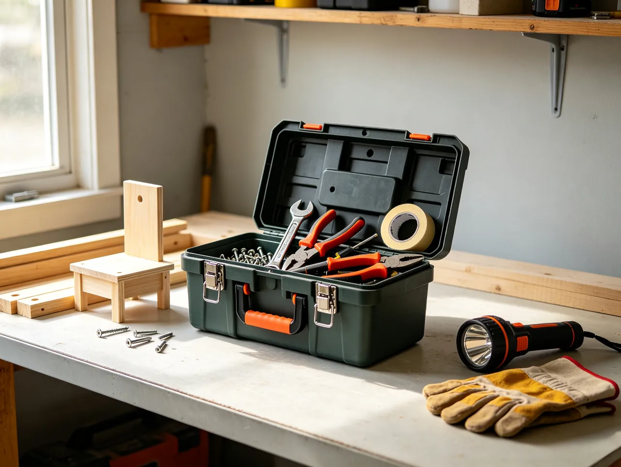
- Put on safety glasses.
- Make a centre dent with a centre punch or small bit so the drill does not wander.
- Drill from inside outwards, so any breakout is on the outside where a sealing washer covers it, at low speed and steady feed.
- Deburr both faces with the deburring tool, then go over them with the round file.
- Clear swarf with a cloth or low-pressure compressed air. Swarf left inside is a common source of later faults, and conductive swarf is genuinely dangerous.
- Measure every cable's outside diameter and check it against the gland clamping range - the step most often got wrong, and with the worst consequences.
Step Three: Fitting Glands and Plugging Spare Openings
- Dismantle a gland and identify the parts: body, sealing insert, clamping claw, locknut, washer.
- Fit the sealing washer on the outside of the enclosure if supplied, pass the body through from outside to inside, and secure with the locknut from inside.
- Reference tightening torque for nylon glands, subject to the manufacturer's data: M16 about 3-4 N·m, M20 about 4-6 N·m, M25 about 6-9 N·m, M32 about 10-14 N·m. Metal glands take a little more. Tight enough but not cracked is the goal; over-torqued nylon develops stress cracks within weeks.
- Pass cables through in order, aiming for the cable diameter to sit in the middle of the clamping range.
- Tighten the locknut, then tug the cable by hand to confirm it cannot be pulled out, roughly 30 to 50 N without slipping.
- Every spare opening must be plugged to the same rating, tightened from inside with a sealing washer outside. Never tape, never sealant, never "it faces downwards".
If the box has a breather vent, fit it now, on the side or bottom as the maker specifies, with the membrane facing out and unobstructed.
Step Four: Four Ways to Fix the Enclosure
| Method | Substrate | Suggested size | Key point |
|---|---|---|---|
| --- | --- | --- | --- |
| Expansion anchors | Concrete, solid brick | M6 light, M8 general, 304 stainless | Drill 5-10 mm deeper than the sleeve; clear dust before fitting |
| Plastic plug plus self-tapper | Solid brick, light partitions, light duty | 8 mm plug with ST4.2 screw | Not for heavy loads or high wind exposure |
| Stainless band clamp | Round or square poles | Band at least 20 mm wide, with rubber liner | Liner grips and isolates galvanically |
| Back plate or sub-panel | Metal framing, racks | M6 bolt with spring washer | Insulate dissimilar metals |
Practical points:
- Anchor torque: typically 8-12 N·m for M6 and 15-25 N·m for M8. Tighten until the sleeve is fully expanded and the washer is flat; do not wrench it, since crushing the brick makes the fixing looser, not tighter.
- Use all four fixing points. Fitting only the top two is a common shortcut, and the result is a lower edge that rocks under wind load until the sealing face fatigues.
- Use the full washer stack. A flat washer plus a spring washer resists vibration loosening; pair stainless bolts with stainless washers to avoid galvanic corrosion.
- On poles: fit the rubber liner first, then the clamps. Use two clamps spaced apart vertically by at least half the box height. Tighten clamp bolts alternately on each side, then go around again for a final pass.
Step Five: Wiring and Termination
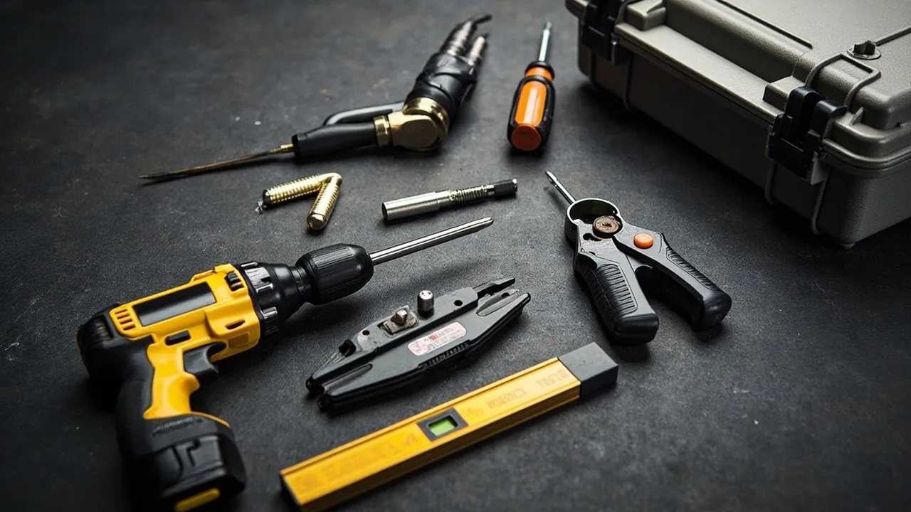
- Form the drip loop first. Once the cable enters, route it down at least 100 mm into a U before rising to the terminals. Any water tracking along the sheath then drips off at the low point instead of reaching the terminals.
- Strip to the length the terminal specifies, usually barrel length plus 1 to 2 mm, so no bare copper is exposed.
- Always crimp a ferrule on stranded conductors - never tighten strands directly under a screw, because they splay, loosen, and heat up. Pull-test each crimp lightly.
- Secure the terminal block and label every conductor. Every wire gets a marker; that saves hours of fault-finding later.
- Route and tie the wiring or use trunking. Keep power and signal separated, ideally at least 100 mm apart, crossing at right angles where they must cross.
- Earth it. Where the enclosure has an earth terminal, connect it with green-yellow cable of adequate cross-section, commonly at least 2.5 mm², subject to the circuit and local rules.
- Leave service length: about 150 to 200 mm of spare cable inside for future re-termination.
Step Six: Sealing, Closing and Tightening Sequence
This step decides whether the IP rating is delivered.
- Inspect the gasket: continuous, not twisted, nothing missing, groove clean. Wipe the sealing face with a clean cloth.
- Confirm nothing is left inside - swarf, screws, tools. In a sealed box these cause short circuits or jam mechanisms.
- Close the lid and tighten diagonally in stages. Go around the bolt pattern two or three times at 50%, 80%, then 100%. M4 is commonly 1.0-1.5 N·m and M5 is commonly 2.0-3.0 N·m, subject to the maker's data. Tightening one bolt fully at once lifts the opposite corner.
- Close every latch fully, until it clicks or seats with a definite feel. Engage any secondary catch.
- Check the joint line: try a 0.05 mm feeler gauge around the whole perimeter. If it will not enter, that is a pass. One minute of work.
- Fit desiccant and a humidity indicator card where the equipment is moisture sensitive.
- Stick an installation record card inside the door or on the outside: date, installer, torque values, cable sizes. Three years later it is worth its weight.
Two additions are worth making at this stage on sites that see regular maintenance. First, take a photograph of the interior before closing, showing routing, labels, and terminal arrangement. It costs nothing and gives the next technician a reference for what "normal" looked like, which is far faster than tracing conductors from scratch. Second, if the installation is one of many on the same project, number the box externally and keep a simple register of number, location, cable schedule, and test results. When a fault appears in year three, that register turns a half-day search into a five-minute lookup, and it also makes the periodic re-torquing programme manageable, since crews can work through the list systematically instead of hunting for what was installed where.
Step Seven: Six Checks Before Energising
- Visual: no damage, firmly fixed, no missed openings, all plugs present.
- Continuity of the protective earth: with the multimeter on continuity, resistance between the enclosure and the earth terminal should be near zero ohms.
- Insulation resistance: at 500 V, between live conductors and earth and between live conductors. Ordinary low-voltage circuits commonly require at least 1 megohm, subject to local rules and equipment requirements. Disconnect electronic components before testing or you will destroy them.
- Wiring review: check every marker and terminal torque, confirm no bare copper and no loose screws.
- Torque re-check: go over every lid bolt and gland again.
- Energising trial: no load first, then load. Watch for fifteen minutes and hand over only when there is no abnormal heating or smell.
Records: log all six results and file them with the installation card. In volume projects this matters most - without records you cannot later tell whether a failure came from installation or from the product.
Eight Frequent Installation Mistakes
Mistake one, cutting entries in the side or top. The most damaging of all. A side entry turns the cable opening into a funnel the moment the seal ages. Bottom entry plus a drip loop is the correct answer.
Mistake two, gland size not matching cable diameter. An oversized gland on a small cable cannot grip; an undersized one stretched over a fat cable cracks the rubber quickly. Measure before fitting.
Mistake three, leaving spare knockouts open. One unplugged opening takes IP67 down to roughly IP20. Fit plugs of the same rating.
Mistake four, tightening bolts fully one at a time. One-sided load warps the lid, tight on one side and slack on the other. Always go diagonally in stages.
Mistake five, substituting tape or silicone for plugs and seals. Temporary measures become permanent; silicone also bonds the gasket to the face, so the next opening ruins the sealing surface.
Mistake six, chaotic internal wiring with no drip loop and no labels. Fault-finding becomes misery, and water tracking along cables reaches the terminals.
Mistake seven, fixing into hollow block or insulation. Wind load and self-weight work the box loose until it falls. Fix to solid material only.
Mistake eight, omitting the earth or earthing poorly. On a metal enclosure the earth is both a safety requirement and an interference measure. Never skip it.
Fixing by Substrate Type and Maintenance Tools
Fixing strategy varies a great deal by substrate:
| Substrate | Recommended fixing | Watch point |
|---|---|---|
| --- | --- | --- |
| Concrete wall or column | M8 stainless expansion anchor | Avoid reinforcement, use a rebar scanner |
| Solid brick | M8 expansion anchor or 10 mm plug | Do not land on a mortar joint |
| Hollow block, aerated concrete | Hollow-block anchor or through-bolt | Ordinary expansion anchors are unreliable |
| Light steel stud partition | Through-bolt with back plate | Limited load capacity |
| Metal pole | Stainless band clamp with rubber liner | Two clamps, galvanic isolation |
| Timber pole | Stainless screws with washers | Watch for splitting and rot |
| Ground slab or foundation | Chemical anchor or cast-in insert | Provide drainage and damp protection |
Suggested maintenance tools and intervals:
| Interval | Task | Tools |
|---|---|---|
| --- | --- | --- |
| 6 months | Re-torque bolts and glands, visual check | Torque screwdriver, spanners |
| 12 months | Gasket inspection, desiccant replacement, clean out | Torch, soft cloth |
| After every opening | Reseat gasket, re-torque diagonally, feeler check | Feeler gauge, torque screwdriver |
| After storm or flooding | Open and check for ingress and condensation | Multimeter, tissue |
| 3 to 5 years | Preventive gasket replacement, depending on material and environment | Full installation kit |
Frequently Asked Questions (FAQ)
Q: What level of electrical skill does installing an outdoor waterproof box require? A: Split it in two. The mechanical work in a de-energised state - positioning, drilling, fixing, fitting glands - is within reach of anyone reasonably handy, provided it is done in the right order and tightened to torque. The wiring, earthing, and energising side should be done by a licensed electrician, because that part concerns personal and equipment safety directly, and local codes impose specific requirements on outdoor circuits such as residual current protection, earthing arrangement, and conductor size. A practical compromise: do the mechanical installation yourself, photograph it, hand the wiring and energising to a licensed electrician together with your installation record card. That saves cost without leaving a safety gap.
Q: Can I drill a plastic enclosure with an ordinary electric drill? A: Yes, but control the speed and choose the right bit. Plastics shed heat poorly, so high speed with slow feed melts the bore and smears material onto the bit, leaving burnt edges and micro-cracks that become splits later. Use a step drill bit at 300 to 600 rpm and back out to clear chips whenever resistance rises; for larger fixed diameters use a hole saw with steady feed and support on both faces to prevent breakout. Always deburr both sides afterwards with a deburring tool or round file, because burrs lift the gland seal and create a leak path. Wear safety glasses: flying plastic swarf causes irreversible eye injury.
Q: Must cables really enter from the bottom? What happens with a side entry? A: Bottom entry is strongly recommended, and gravity is the reason. A downward-facing entry does not hold water, so even as the seal ages water cannot climb against gravity. A side or top entry, once the seal ages, becomes a funnel that runs water straight down the cable sheath into the box, with the terminal block first in line. If site conditions genuinely force a side entry, do three things: form a drip loop of at least 100 mm inside the enclosure; use a high-rated gland with a sealing washer and tighten it to torque; and list that point for shorter inspection intervals. All three are mitigations, and none is as reliable as bottom entry.
Q: What torque should a cable gland be tightened to, and is tighter better? A: Tighter is not better. Typical reference values for nylon glands are about 3 to 4 N·m for M16, 4 to 6 N·m for M20, 6 to 9 N·m for M25, and 10 to 14 N·m for M32, with metal glands a little higher and the manufacturer's data taking precedence. Under-tightened, the seal cannot grip and water tracks in; over-tightened, nylon develops stress cracks that often appear only weeks later, by which time sealing is gone. Two practical ways to judge: use a torque screwdriver set to the value, or pull the cable by hand after tightening and confirm it does not slip at roughly 30 to 50 N. And check the clamping range against cable diameter first - that step goes wrong more often than torque does, with worse consequences.
Q: Is it acceptable to leave spare knockouts unplugged? A: No, never. An unplugged knockout is equivalent to dropping from IP67 to roughly IP20: dust, insects, and rain come and go freely, and the risks of condensation and short circuits rise sharply. Plug every spare opening to the same rating, tightened from inside with a sealing washer outside. Tape, sealant, and "the hole faces down so it should be fine" are not acceptable - tape fails outdoors within months, and silicone bonds to surrounding parts with limited weathering life. Specify that plugs are supplied when you buy, because many low-cost enclosures ship without them, and a site that cannot find one will improvise.
Q: How can I tell quickly whether the seal is good after installation? A: Three levels. Fastest is the feeler gauge: with the lid closed and latched, try a 0.05 mm gauge around the whole joint; anywhere it enters is under-compressed. It takes about a minute and needs almost no equipment. Second is a spray screen: wet slowly along the joint for a few minutes, then open and look for water. Do this de-energised, and note it does not substitute for a standard test. Third is pressure decay: fit an air nipple, pressurise to about 5 kPa, and watch the drop over thirty seconds; more than 10% to 20% indicates a leak path. This one is quantifiable and practical on volume installs. All three are field screens and none replaces third-party type testing to IEC 60529.
Q: What size expansion anchor should I use to fix the box? A: M8 stainless, 304 grade, is the normal choice for an outdoor waterproof enclosure; M6 suits small light boxes. The substrate matters more than the bolt size. Concrete and solid brick take expansion anchors directly. Hollow block and aerated concrete need hollow-block anchors or through-bolts with a back plate, because ordinary expansion anchors simply cannot grip in a void. Lightweight partitions have limited capacity and need through-fixing. Torque is typically 8 to 12 N·m for M6 and 15 to 25 N·m for M8, taken to the point where the sleeve is fully expanded and the washer is flat - wrenching harder crushes the brick and makes the fixing worse. Use all four points; fixing only the top two lets the lower edge rock under wind load until the sealing face fatigues.
Q: What should I watch when mounting on a metal pole? A: Three things. Use stainless band clamps with a rubber liner, because the liner grips and also isolates galvanically - an aluminium or steel pole in direct contact with stainless in damp conditions will corrode. Use two clamps spaced vertically by at least half the box height, so they resist the overturning moment from the box weight, and tighten the clamp bolts alternately on each side before a final pass. Assess the pole itself: match clamp size to pole diameter, repair any damaged galvanising first, and on a timber pole keep screws away from existing checks while planning for eventual rot. In coastal or chemical environments specify 316 for both clamps and bolts.
Closing Thoughts and Further Reading
Three sentences carry it: sequence beats tools - drill before fixing, bottom entry before wiring; torque beats force - tighten lid bolts diagonally in stages and glands to a number; records beat memory - log the date, the torque, and the cable sizes.
Installing an outdoor waterproof enclosure is not technically demanding, but it is unforgiving of detail. One unplugged hole, one lid tightened without a diagonal sequence, one gland of the wrong size, and the IP67 designed into the product counts for nothing. Run the seven steps, then spend a minute each with the feeler gauge and the torque screwdriver, and the great majority of water ingress problems never arise.
JUNZHJIA enclosures are manufactured by Kexin New Materials (Guangdong) Co., Ltd. at its Zhongshan plant. Waterproof junction boxes and electrical enclosures ship with plugs of matching rating and installation instructions, and gland selection tables, torque data, and installation work instructions are available. OEM/ODM and volume supply worldwide are supported.
Further reading