

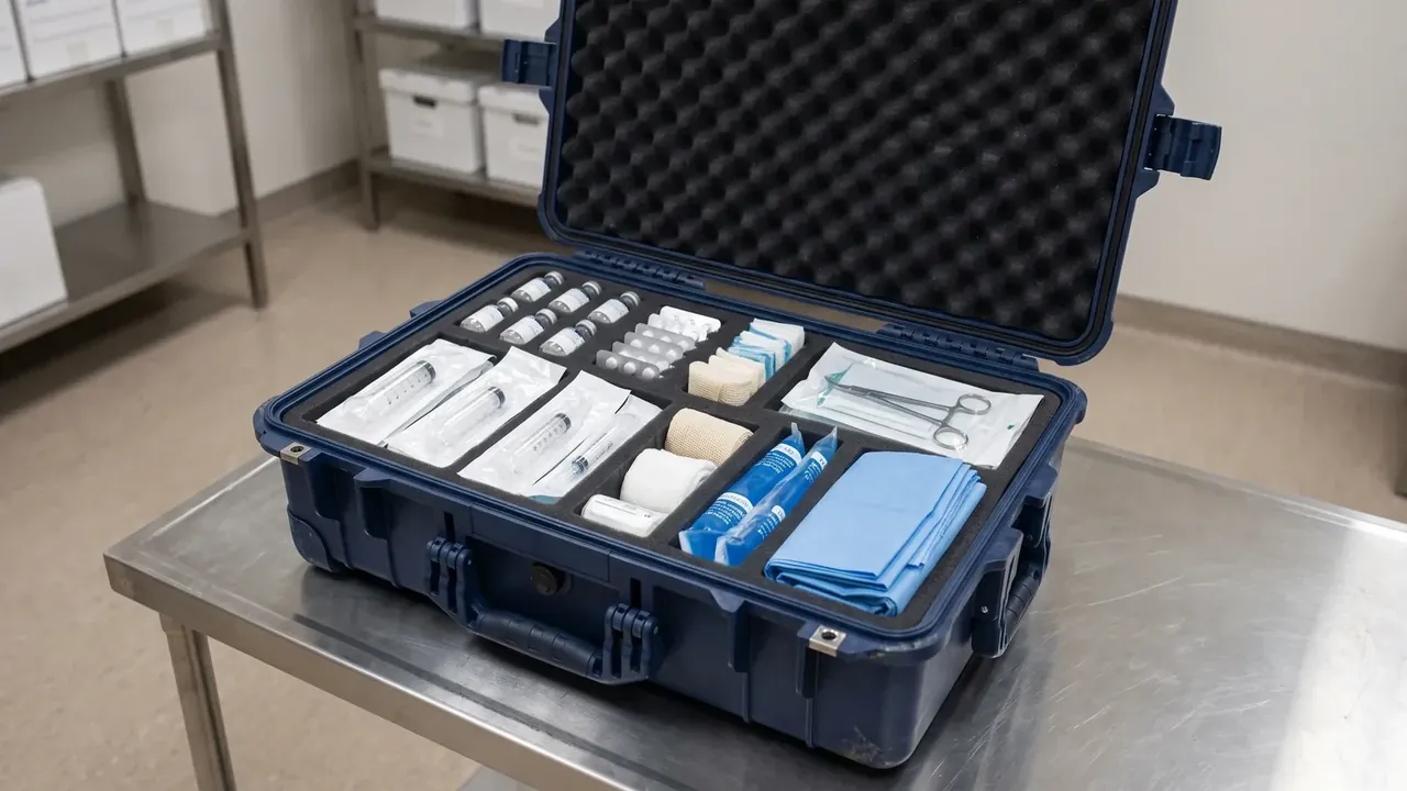
Quick answer: Three cheap case structure custom moves — 20 mm taller, 15 mm wider, two dividers — cost 15% of the original tool and lift the rating to 150 kg.
Table of contents
- Where a case structure custom starts
- 20 mm taller: height, cavity and stacking
- 15 mm wider and two dividers
- 3.5 mm walls versus six ribs
- Three retests after a structural change
- FAQ
1. Where a case structure custom starts
The request was 20 mm taller; the quotation came back with slide travel, cooling circuits and ejection. On a 500 × 365 × 200 mm case with a 450 × 320 × 170 mm cavity, those 20 mm deepen the cavity to 190 mm and lengthen the side core, so the two slides no longer fit.
A case structure custom has three entry points: height, width and internal division. Height moves cavity depth and slide travel, width moves the parting line and circuit pitch, dividers move core inserts.
| Change | Outer size | Cavity | Tool work |
|---|---|---|---|
| 20 mm taller | 200→220 mm | 170→190 mm | Cavity +20 mm, slide travel +20 mm |
| 15 mm wider | 365→380 mm | 320→335 mm | Parting line out 15 mm, 2 circuits moved |
| Two dividers | Unchanged | 3 cells, 103 mm clear | 2 core inserts, pins 12→16 |
| Wall 3.0→3.5 mm | Unchanged | 1 mm less per side | Cavity relieved, clamp +15% |
Height and width each disturb one slide and two circuits; dividers touch only inserts. All three at once are charged at 15% of the original tool; beyond that the tool is rebuilt, as a rework runs 30,000 shots short.
2. 20 mm taller: height, cavity and stacking
Height is the only change that alters the envelope. Outer height goes 200→220 mm and cavity height 170→190 mm while the gasket groove stays put, so sealing looks unaffected — but the lid deflects 0.6 mm at 0.03 MPa instead of 0.4 mm, and gasket compression falls with it.
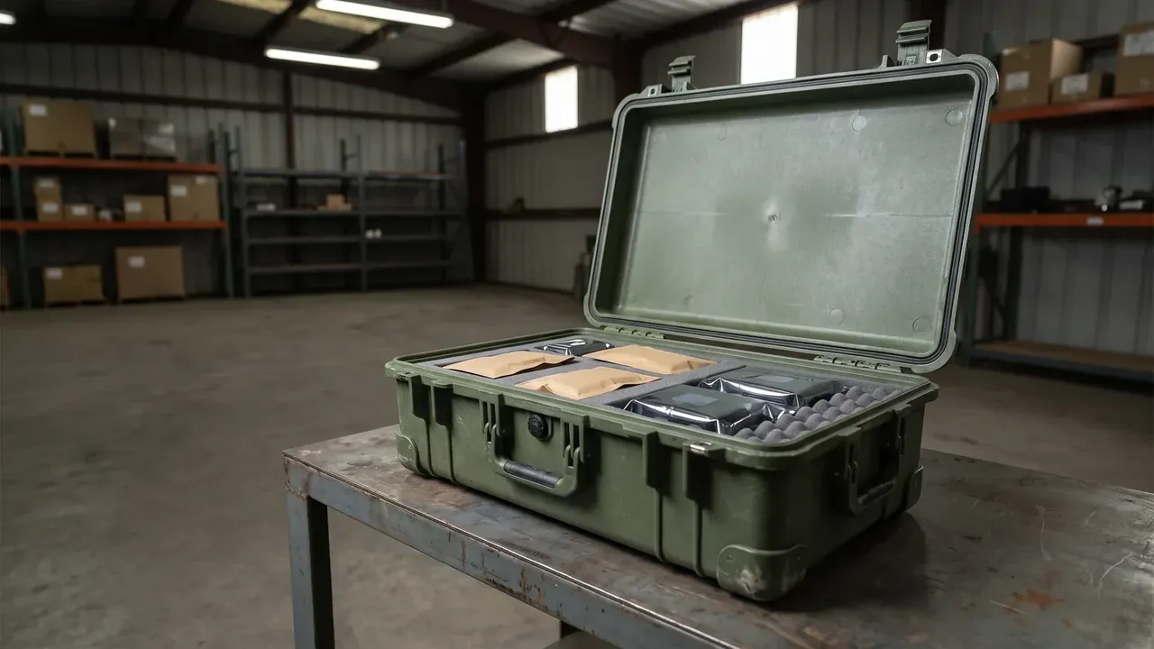
Circuits fail first: the deepest point sits 22 mm from the cavity face, becomes 30 mm, past the usual 25 mm limit, and the base sinks. Two more angled circuits are the only fix.
Slide travel forces a new cylinder: 50 mm becomes 70 mm and the shot moves from 55 s to 57 s. Stacking is worse — three warehouse layers put 66 kg on the bottom case, eight truck layers put 176 kg on it, past the 150 kg rating, so the load stops at 6 layers and 11% of load factor goes.
Half the cost of those 20 mm lands on the load factor, not on the tool.
3. 15 mm wider and two dividers
Width moves the parting line. Outer width goes 365→380 mm and cavity width 320→335 mm, so with the same base the side clearance falls from 18 mm to 10.5 mm — too little for lifting, and the base goes up one size.
Circuits are respaced: 65 mm pitch becomes 72 mm, and the freed 15 mm leaves a 40 mm band with no cooling, so 2 circuits go back at 68 mm pitch. Two dividers leave the outside alone: 450 × 320 mm splits into 3 cells of 103 mm clear width.
A wall 4 mm thick and 170 mm tall has an aspect ratio of 42 and distorts on ejection: it needs R1.5 at the root, 1° of draft and a 0.02 mm vent groove each side. Pins go from 12 to 16, so the ejector plate is new and the stroke grows from 45 mm to 50 mm.
Two dividers are the cheapest option and the easiest to ruin: a wall that leans 0.3 mm gives cells of 102.4 mm and 103.6 mm.
4. 3.5 mm walls versus six ribs
Reaching 150 kg from 120 kg has two routes. A 3.0→3.5 mm wall raises unit weight from 4.2 kg to 4.51 kg, lengthens cooling by 36% and moves the shot from 55 s to 72 s; the bill arrives in cycle time and weight.
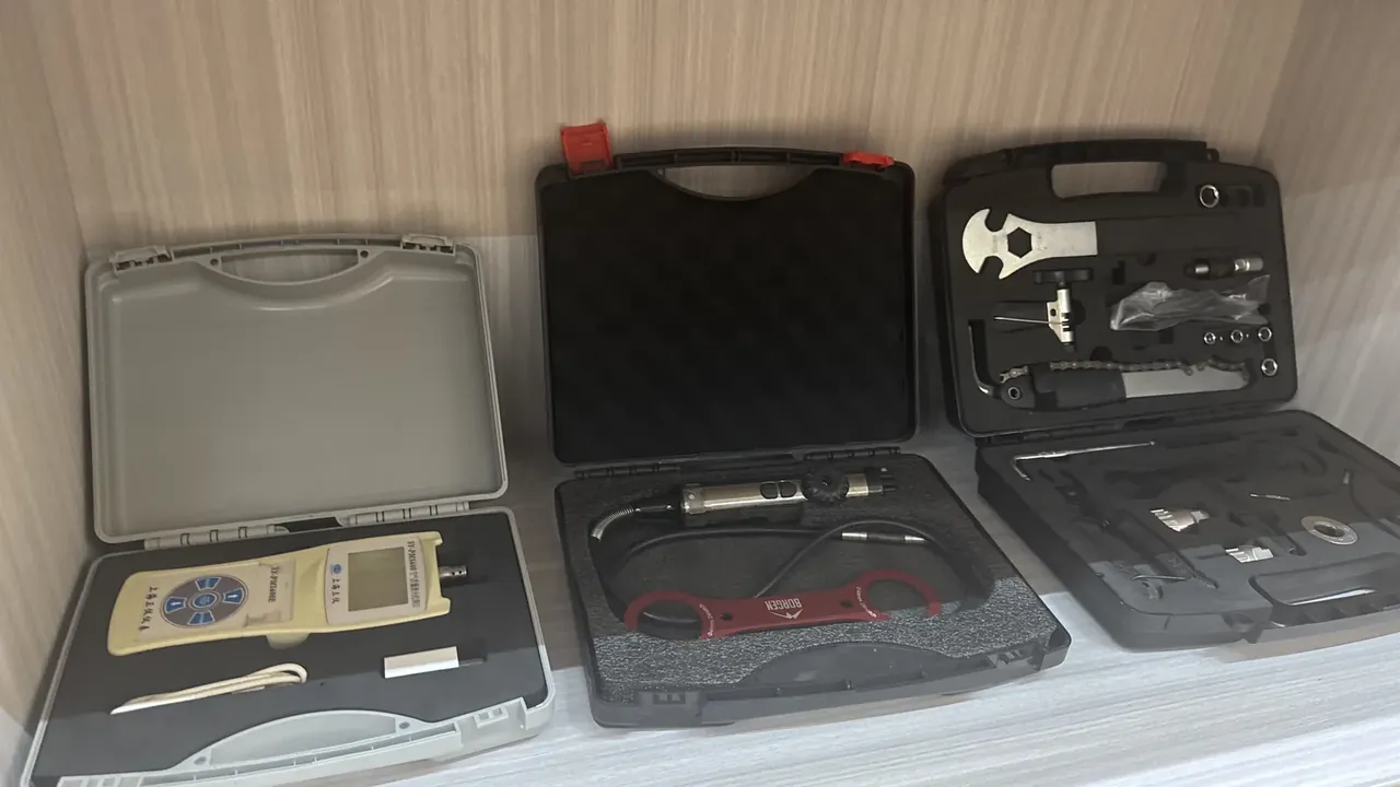
Six ribs take the other route: 2.0 mm thick, 18 mm tall, 65 mm pitch, R1.5 at the root, across the base and long sides. They add 0.09 kg, raise bending stiffness 30% and cost 2 s of cycle.
| Option | Added weight | Stiffness | Cycle | Tool work |
|---|---|---|---|---|
| Wall 3.0→3.5 mm | +0.31 kg | +22% | 55→72 s | Cavity relieved, clamp +15% |
| Six ribs | +0.09 kg | +30% | 55→57 s | 6 grooves in the cavity |
| Both | +0.38 kg | +41% | 55→74 s | Relief plus grooves |
Ribs have one trap: a 2.0 mm rib on a 3.0 mm wall is a 0.67 ratio, and above 0.6 it leaves a 0.05 mm hollow on the visible face. At 1.8 mm the hollow drops to 0.02 mm.
Three conditions decide it. If the rating needs 30 kg more and the case sits in a stack, ribs are enough — 6 grooves, no change to parting line or circuits, the lightest case structure custom change on offer. Above 60 kg, or below −20 ℃, ribs fail: a rib root is a stress raiser in the cold, the wall must grow first, then the latch boss needs 10 mm of engagement instead of 8 mm. Third, a 3.5 mm wall needs 15% more clamp force, so the 530 t press is rechecked.
5. Three retests after a structural change
Any structural change voids the old report. The minimum is three retests: airtightness, drop and stacking.
Airtightness is immersion: 1 m of water, 30 min, no continuous stream of bubbles. It is repeated although the groove did not move, because compression fell from 30% to 26% as the lid softened.
Drop follows 0.9 m, 6 faces, 3 edges and 1 corner, 10 drops, passing if the case still latches 5 times without a crack. With 20 mm more height the centre of gravity rises 8 mm and impact moves to mid-edge.
Stacking is 3 layers, 150 kg on the bottom case, 72 h, no more than 2 mm of set after 1 h; lid interference at a 190 mm cavity must stay inside 0.5 mm.
A divider-only project can skip the drop test, since size and weight are unchanged. Airtightness and stacking cannot: the walls move the lid supports and stacking pressure rises.
Conclusion
Work the case structure custom decision backwards: fix the load and rating, derive the structure, look at the tool last. Thirty kilograms short, and six ribs settle it for 2 s of cycle. Cavity height short, and 20 mm costs 2 more circuits plus 11% of load factor. Two dividers only when the cells are needed. Do all three and the tool change sits at 15% of the original with 18 days extra, after which airtightness, drop and stacking must all be re-run. If 15% and 18 days buy back the missing rating and cavity, rework the tool; if not, build for the new structure.
| Change | Tool work | Lead time | Unit cost | When it pays |
|---|---|---|---|---|
| Two dividers | Lightest, core inserts only | +6 days | +8% | Cells needed, outside fixed |
| 20 mm taller | Medium, 2 circuits and slide travel | +8 days | +6% | Cavity 20 mm short |
| 15 mm wider | Heaviest, may need a new base | +12 days | +7% | Part wider than the cavity |
| All three | 15% of the original tool | +18 days | +19% | New product, one round of changes |
This article discusses container-side specifications and design implications only, and does not cover any handling, loading or use of the contents.
Related Reading
- Stacking structure and load capacity
- Custom size plastic case specifications
- How reinforcement ribs are laid out
- Airtight leak testing in practice
Related Products
- 8 Series — Gun Cases; Military Equipment Cases; Camera Equipment Cases; Drone Cases; Watch Cases; Knife Cases; First Aid Cases; Electronics Equipment Cases
- WL8-2812 PP Gun Case — model WL8-2812
- All protective cases and toolboxes: 7 series, 158 models