

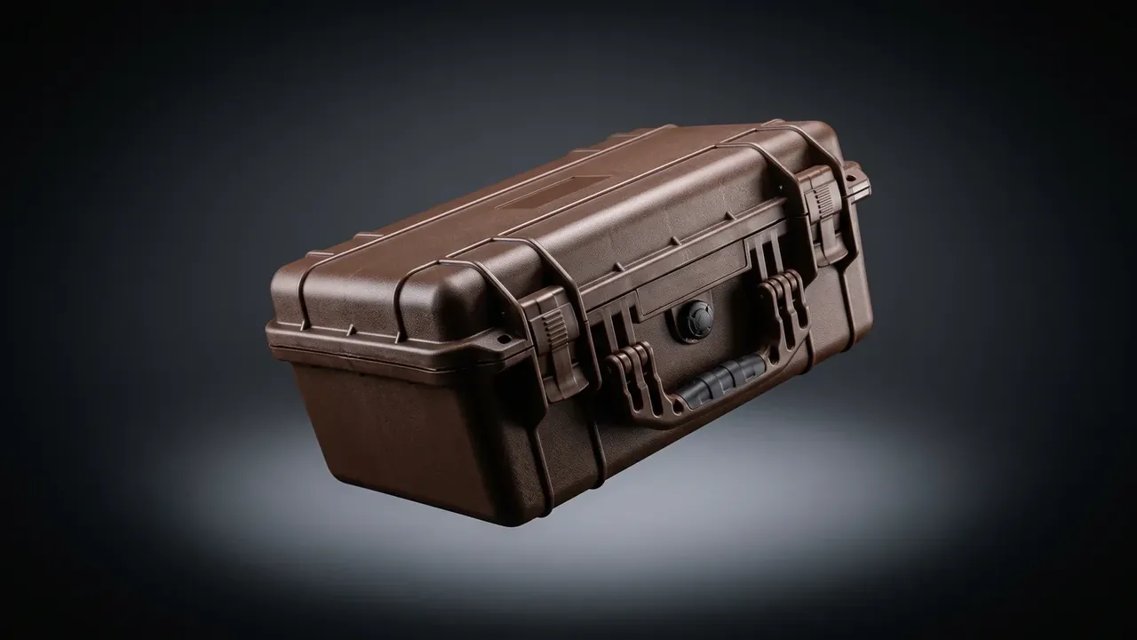
Quick answer: A 700×1000×600 mm CMM travelled 380 km for annual calibration, and the testing equipment protective case was the easy part. Pad compression, bolt order and second lifts decided the result. What follows: 25 mm pads, 6 N·m diagonal torque, a 0.02 mm/m level check, arrival re-verification.
Table of contents
- What this testing equipment protective case had to carry
- Loading the CMM: pad thickness and bolt order
- Spectrometer and accessory bays
- Level and pad compression checked on site
- Counting the second lifts
- Paperwork inside the case and re-verification on arrival
- FAQ
1. What this testing equipment protective case had to carry
A tier-two automotive supplier in Suzhou sends a four-year-old CMM 380 km for annual calibration. Two earlier trips went in a timber crate, and the Z-axis error arrived at 4.7 μm instead of 2.1 μm — inside tolerance, but enough for an auditor to ask why.
Three dimensions came first: door clearance 1.6 m, tail-lift height 0.9 m, lifting-point spacing 1.2 m. They decide whether the machine travels assembled.
The load is four items.
| Item | Net weight | Envelope mm | Sensitive point |
|---|---|---|---|
| CMM main unit | 620 kg | 1180×1420×2050 | guideways and glass scales |
| Control cabinet | 45 kg | 600×800×1200 | board connectors |
| Portable spectrometer | 18 kg | 480×380×220 | optical window |
| Probe and master ball | 3.2 kg | 210×160×90 | ruby tip |
The envelope of the testing equipment protective case is set by the longest item, the interior split by the most sensitive one.
2. Loading the CMM: pad thickness and bolt order
A cast-iron base cannot sit straight on the case floor. Without continuous bearing, four uneven contacts twist the column.
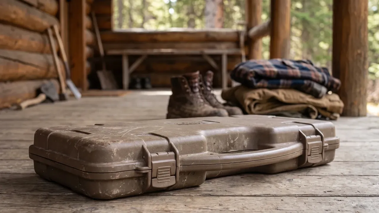
Padding is 25 mm closed-cell EPDM, cut into 120 mm × 100 mm blocks at six points, never one sheet. A sheet leaves the base spanning air and turns the pad into a drum skin.
Thicker is not better; past 30 mm the machine rocks.
Torque goes diagonally: two diagonal points at 6 N·m, the centre pair at 2 N·m preload, the last two re-tightened after two hours because the foam creeps 1 mm. Four hours on, two points had fallen to 5.2 N·m.
One pass never holds.
3. Spectrometer and accessory bays
The main unit takes seven tenths of the interior; the rest of the testing equipment protective case goes to the spectrometer and accessories, listed rather than tabulated because each is counted as it goes in.
- Portable spark spectrometer, 18 kg, own bay with 15 mm clearance
- Electrode stand and spark stand on the shelf above that bay
- Four reference blocks, each in a slot 12 mm deep
- Two argon hoses coiled to 200 mm and tied to the wall
- Mains and signal leads in one bundle, 50 mm slack at each end
- Manual and certificate copy in a dry bag on the top layer
- Two spare probes, ruby tips up, in foam pillars
Bays exist so counting is possible. Read the list aloud, then close the lid; a missing part surfaces on arrival and costs two days.
4. Level and pad compression checked on site
Packing is not the finish line. Before the lid closes, level is read again at four points on the worktable.
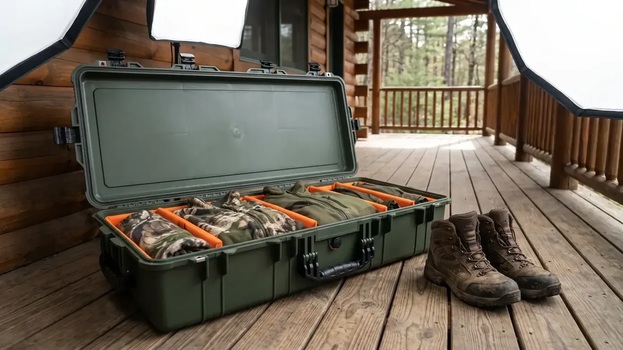
The spread must stay inside 0.02 mm/m. Tolerance is 2.5 μm, and every 0.01 mm/m adds about 0.4 μm of cosine error over a 1 m stroke, leaving no margin for road vibration.
Compression is read at the same time. A 25 mm pad under 103 kg per point should compress under 3 mm.
Order matters too. Empty case first, machine in second, two hours after torque third. The readings went on one sheet: 0.008, 0.014 and 0.011 mm/m. If the third is worse than the second, look at the bolt order, not the shell.
5. Counting the second lifts
Count the lifts: four on this route — pallet truck, tail lift, tail lift, forklift — and two involved a turn.
Straight runs peaked at 1.8 g; a turning lift peaked at 3.4 g, because one side leaves the ground and load runs through the pad edge.
Avoid the turn.
Tilt indicators stayed clear; a 20 mm corner scuff showed a grazed van pillar.
6. Paperwork inside the case and re-verification on arrival
Paper travels too inside the testing equipment protective case: certificate copy, packing list, torque record and level readings, in a dry bag.
Three checks on arrival.
| Check | Criterion | Recorded by |
|---|---|---|
| Repeatability | within 1.0 μm of factory value | laser interferometer, three points |
| Indication error | within 2.5 μm over full range | five-step gauge block comparison |
| Probe trigger force | within 0.02 N in any direction | force gauge, probe by probe |
Repeatability moves first. It follows shell stiffness, but also pad shift: 5 mm of shift can cost 0.6 μm.
Conclusion
Most of a calibration trip is settled before the lid closes. Counting the load, cutting the pads, torquing diagonally and re-reading the level keep numbers stable over 380 km. Holding those conditions is the job of a testing equipment protective case.
This article discusses only the container (case body) side of specifications and design intent, and does not cover any handling, loading or use of the contents.
Related Reading
- How equipment cases differ between workshop and field
- Loading points and lifting layout for large cases
- ESD control and bay layout in electronic equipment cases
- From drawing to production in OEM case projects
- Camera cases configured for field shoots and transit
Related Products
- 8 Series — Gun Cases; Military Equipment Cases; Camera Equipment Cases; Drone Cases; Watch Cases; Knife Cases; First Aid Cases; Electronics Equipment Cases
- WL8-2812 PP Gun Case — model WL8-2812
- All protective cases and toolboxes: 7 series, 158 models