

The slewing ring and the luffing gear of a tower crane are the two assemblies most easily destroyed by "ordinary vibration" and "unintended loading" during site transfers and long-haul road transport. A single brinelling mark on the gear tooth flank that is nearly invisible to the naked eye becomes a full-circle vibration complaint once the ring rotates on site. A few millimetres of groove wear in a luffing sheave silently drops the safe working load well below the nameplate figure. What makes these two assemblies especially unforgiving is that they are assembled and serviced tens of metres up a tower, where site conditions offer neither cleanliness nor repair capability. Once they are damaged in transit, the only remedy is to shut the crane down and wait for replacement parts.
JUNZHIJIA approaches tower crane component cases with a single governing principle: no component is permitted to move inside its case during transport. Internal liners and locking structures are engineered around the maximum envelope and load path of each item — the ring gear, the support plates, the luffing cylinders, the pins, the wire ropes and the sheaves — so that the assembly relationship is held by geometric constraint for the entire journey, rather than left to the friction of stretch film and generic foam.
Table of Contents
- Pitting and Brinelling on Slewing Ring Gear Tooth Flanks
- Retaining and Re-tightening Support Plate Bolt Preload
- Broken Wires in Luffing Wire Ropes and Sheave Groove Wear
- Barrel Coating Scratches and Seal Failure on Luffing Cylinders
- Field Rejection Criteria for Ovalised Pin Holes
- High-Altitude Protection of Tower Section Chord Node Bolts
- Jib Truss Node Integrity and Tip Deflection Control
- Case Attachment and Lashing Under Wind and Snow Loads
- Separate Ring Packaging for the Ring Gear and Compartment Layout
- Compartment Design for Pin Corrosion Protection and Loss Prevention
- Weighing Knock-Down Packaging Against Monolithic Packaging
- Arrival Acceptance Criteria for Tooth Flanks and Bolt Holes
- Coating Selection for Wind, Sand, Rain, Snow and Coastal Salt Mist
- Frequently Asked Questions FAQ
- Conclusion and Related Reading
Pitting and Brinelling on Slewing Ring Gear Tooth Flanks
Almost the entire load-carrying cross-section of a slewing bearing concentrates on the raceway tooth flank. Any "hard contact" across the tooth width during transit — for example, a support plate settling 2 mm inside the case and letting the ring gear grind along the same tooth flank for tens of kilometres — ends as pitting, scuffing or local brinelling.
Brinelling in a transport scenario has a typical origin. The ring gear is a thin-walled annular part. If the packaging only addresses "rust protection on top, support from below", case vibration transfers impacts through the bolt-hole locations into the outer rim. Once that seating face is dented beyond 0.3 mm, raceway contact stress degrades immediately and the damage multiplies during site slewing.
JUNZHIJIA treats the ring gear as a precision thin-walled component rather than a generic ring:
| Ring gear failure mode | Transport-phase trigger | Case structural measure | Trace visible on arrival |
|---|---|---|---|
| --- | --- | --- | --- |
| Tooth flank pitting | Relative movement inside the case, dust abrasion | Full-circumference locating step, zero degrees of freedom | Uneven contact band width, pitting pits |
| Rim brinelling | Localised hard contact, stacking impact | Annular end pad plus no direct hard contact | Continuous dents, ovalisation of the rim |
| Ovalised bolt holes | Repeated swinging, hole-wall crushing | Support plate holes co-axial with case datum holes | Feeler gauge will not enter when out of tolerance |
| Water ingress into the seal cavity | Wiper lip scraped by a hard object | Sealing ring suspended in its own cavity | Water traces and rust rings on the cavity wall |
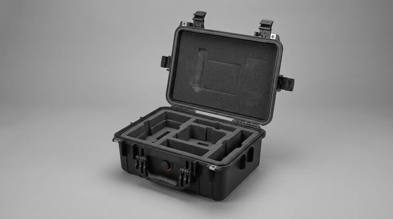
The ring gear must be constrained "at three or more points around the full circumference", not held at two diagonal points. JUNZHIJIA uses a liner built as a "locating step plus segmented circumferential soft pads": the step carries gravity and vibration acceleration, the soft pads only close the gap. The duties stay separate, so cushioning material is never held in continuous compression until it fails.
Retaining and Re-tightening Support Plate Bolt Preload
The upper and lower support plates of a slewing bearing are joined into a rigid ring frame by dozens of high-strength bolts, and bolt preload is the entire life of that joint. After a tower crane is erected on site, that preload must be maintained for years, because the overturning moment during slewing is transferred entirely through it.
Preload loss in transit follows three paths. Vibration shakes the bolts loose. Residual welding deformation in the support plates "breathes" under repeated loading and shifts the bolt-hole positions. Seal failure lets rainwater creep down the bolt holes, forming corrosion expansion at the thread root that eats the preload away.
The case measures addressing those three paths are as follows:
- Vibration path: preloaded bolts are not disassembled at all; they travel with the support plate as one packed assembly. The case contains no fastener that must be tightened on site, which removes the temptation to skip the re-tightening step entirely.
- Welding deformation path: upper and lower support plates are fixed on a "three-point fixture" arrangement inside the case, limiting relative warping. The case itself is designed with at least 25 mm of clearance beyond the support plate outline so the plate can never be pushed by the case wall and forced out of shape.
- Water ingress path: the bolt-hole zone receives its own dry compartment with desiccant and a visible inspection window. Sealing faces point upward to eliminate the "pocket effect" that traps water.
Re-tightening on site is unavoidable, but the target is "return to the factory preload", not "tighten as hard as possible". Support plate bolts are normally staged at roughly 1.1 times the specified preload in a diagonal cross pattern. Any missed or over-tightened bolt leaves the ring gear loaded on one side. That requirement belongs in the packing documentation, not a telephone briefing.
Broken Wires in Luffing Wire Ropes and Sheave Groove Wear
The wire ropes, sheave block and rope-retention devices in the luffing mechanism form the only flexible system on a tower crane that carries high tension and high cycle counts simultaneously. In transit, ropes are less afraid of tension than of reverse spooling, opened strands and cut damage.
A 16 mm four-by-thirty-six wire rope has a minimum breaking load above 100 kN. The real problem is that once a rope is compressed into a figure-eight or a hand-truck shape inside the case, unloading leaves permanent plastic deformation inside the wires. When the rope is re-threaded on site, its straightness has changed, contact stress in the sheave groove doubles, and the groove edge starts producing burrs and broken wires. Ring and sheave groove preservation follows the same logic as Bearing & Gearbox Cases, where the fit surface is treated as a protected feature rather than a structural one.
Sheave groove wear is easier to overlook. A luffing sheave groove wall has only a few millimetres of usable thickness, and a single skewed run cuts an off-centre hollow into the groove bottom that every later cycle enlarges.
Protection rules inside the case:
- The rope must be coiled in concentric circles, with a minimum coil diameter of twenty times the rope diameter. Reverse twisting is prohibited.
- No radial clamping force may act on the rope. Separation is achieved with degradable flat woven bands acting as spacer rings, not with foam squeezing the rope to death.
- Sheaves go in their own compartment with the groove facing upward, and no hard debris may fall into the cavity. Groove walls receive rust preventive grease and a non-woven wrap.
- Rope clamps, cotter pins and keeper plates go into a separate compartment, physically isolated from the rope — this is the single most frequently lost group during transport.
On arrival, inspect the rope along its entire length under good lighting for broken wires, end wear and lubricant residue. The GB/T 8918 rejection criteria are ten broken wires within one rope pitch, or outer-layer wear reducing the diameter to seven tenths of nominal. Print those numbers on the acceptance page of the packing documentation.
Barrel Coating Scratches and Seal Failure on Luffing Cylinders
Luffing cylinders are the tower crane components most easily damaged invisibly in transit. The barrel chrome or nitrided layer is only a few micrometres thick, and a single rub from a hard object leaves a scratch. Once the scratch penetrates the coating, rust starts at that point in humid air and spreads along grain boundaries, producing corrosion fatigue.
A barrel scratch carries a second consequence: the piston rod wiper ring scrapes dirt away from the cylinder mouth, and burrs raised by the scratch catch the seal and tear the sealing lip repeatedly.
The same compartment logic used for Excavator Parts Cases applies here. JUNZHIJIA uses a "three-point suspension plus full-length end location" scheme for luffing cylinders:
| Risk point | In-case protection | Acceptance focus |
|---|---|---|
| --- | --- | --- |
| Barrel coating scratch | Continuous non-woven wrap plus buffer sleeve; no hard straps | Wrap unbroken; no wear marks when the barrel is rotated |
| Rod end striking the mouth | Independent limit blocks at rod end and mouth, swing held within 1 mm | Limit blocks not crushed or deformed |
| Coating absorbing moisture | Desiccant compartment plus V-seal at the rod end to stop convection | Seal intact, no condensation |
| Valve block and rigid pipes | Valve block suspended separately, rigid pipes in their own compartment | Nameplate legible, threads undamaged |
| Piston rod bending | Supported along the full length, support spacing under five times the bore diameter | Full-length straightness check passes |
The step most often skipped is cylinder venting. If air is trapped inside the barrel, moisture ingress can form rust water and even emulsify the oil in the piston chamber. The cylinder must therefore sit horizontally or with the mouth slightly downward, and that orientation requirement must appear explicitly in the packing documentation.
Field Rejection Criteria for Ovalised Pin Holes
Pin joints on a tower crane concentrate at the jib root, the counter-jib root, the luffing tie-rod lugs and the luffing fork lugs. Ovalisation of a pin hole is the most common transport damage to these structures.
Pin holes carry enormous bearing stress in service. If a pin merely sits "in the hole" during transport without axial location, case shake drives it back and forth against the bore wall, crushing the wall into an ellipse and raising a burr at the mouth.
Field rejection criteria must be hard numbers:
- Roundness and ovality: measure two mutually perpendicular directions on the same cross-section with an inside micrometer or plug gauge. A difference beyond 5 percent of the bore diameter is out of tolerance. Tower crane pin bores are normally manufactured to H11, and ovality created in transit cannot be repaired on site.
- Mouth burrs: any visible raised edge or burr is a reject. Any burr will tear the weld when the pin is loaded.
- Hole position tolerance: a centre distance from the adjacent datum hole deviating beyond twice the drawing tolerance requires dismantling and re-welding the part to correct the geometry.
- Directional consistency of the oval: if the long axis of the oval points consistently along the case acceleration direction, the damage originates from insufficient case restraint and the packaging design must be reviewed, not just the part repaired.
Only two remedies exist: replace the lug or fork plate carrying the bore, the recommended route, or have a certified welder perform a process-qualified bore insert and re-machine. The third route, "keep running it and watch it", is not permitted, because an ovalised bore degrades the pin from area contact to line contact and multiplies shear stress.
High-Altitude Protection of Tower Section Chord Node Bolts
Tower sections join chord and diagonal members into a truss column with high-strength bolts. This "bolt group plus welded gusset plate" joint is equally sensitive to hole position accuracy and to bolt preload.
The central difficulty is that tower sections generally cannot be fully assembled on the ground; final assembly happens at height. If a bolt group loosens in transit, every bolt replaced on site means one more high-altitude exposure, and a hole stretched in transport is extremely difficult to ream at height.
Practice inside the case:
- Sections are loaded lying down with four-point restraint, chords downward and diagonals lateral, so the bolt group never carries a bending moment.
- Bolts and gusset plates are not disassembled; they travel protected as a unit. If dimensions force separation, the "gusset plate plus bolts plus matching locating pins" travel in one compartment, with pins guaranteeing reassembly position.
- Bolt threads receive anti-seize compound and corrosion inhibitor, with individual plastic caps so bolts cannot collide and gall the threads in transit.
- Plates are separated by spacer blocks placed clear of the bolt holes so the holes are never crushed.
Field re-tightening must likewise be staged and diagonal. Tower section bolts are normally staged at 1.1 to 1.3 times the specified preload, and the work should be done only after wind has dropped. Wind load at height significantly changes the real bolt forces, so the torque-wrench reading is not a reliable representation of actual preload.
Jib Truss Node Integrity and Tip Deflection Control
The jib and counter-jib are slender lattice structures whose dominant transport risk is overall flexural distortion. If a truss is lifted from only two points, or rests on a single support inside the case, vibration during transport produces permanent plastic deformation.
Tip deflection has a direct consequence. Jib outreach is calculated from a design deflection figure, so additional deflection introduced by transport eats directly into safe working load and lifting height. Worse, a truss that does not fully spring back leaves an out-of-straight axis after assembly, which unloads the luffing sheave block unevenly. The staged handling discipline used for oversize fabrications is set out in Heavy Duty Cases.
JUNZHIJIA's truss packaging follows a "multi-point support, zero cantilever" principle:
| Truss member | Support arrangement | Permitted transport distortion |
|---|---|---|
| --- | --- | --- |
| Jib main chord | Support block every 3 to 4 m | Chord straightness within 3/1000 of span |
| Counter-jib main chord | Support block every 3 m plus end tensioning | End rise no more than 5 mm |
| Diagonal web member | Suspended individually, never stacked | No permanent kinks |
| Cotter pins and pins | Dedicated compartment | No corrosion, no loss |
Truss packaging often exceeds 6 m in length and is therefore an oversize item. That places a demand on case stiffness: the floor must carry intermediate cross members, otherwise it sags under its own weight and bends the truss. Vibration frequency in an oversize case differs completely from a standard case, so conventional rib layouts cannot be reused. Self-weight and lifting-point layout should be checked against the load calculation used for heavy-duty cases.
Case Attachment and Lashing Under Wind and Snow Loads
Transport of tower crane components often involves a condition that is easy to overlook: while sitting in an open yard or being transferred, the case may be subjected to wind and snow loads comparable to its own weight. This is particularly true on coastal and high-altitude projects.
Wind load is high frequency plus long duration, which drives micro-resonance inside the case. Resonance amplifies transport damage: an amplitude of only 0.2 mm, sustained for hours, lets the ring gear grind continuously against its support plate.
Snow load is far more concrete. Snow on the roof adds top-side pressure, while case capacity is normally designed for a roof crew can stand on, so snow is an unintended load. Meltwater seeping into gaps then sets up a condensation cycle inside the case.
Attachment and lashing design must therefore cover these conditions:
- Yard state: the case base carries ground anchor lugs or lashing eyes so it can be tied to ground anchors and cannot be flipped by strong wind.
- Open-air stacking state: adjacent cases are joined with webbing plus buckles, tensioned to the rated load rather than merely "looking tight".
- Snow load case: roof design live load is checked at not less than 1.0 kN/m2, and the roof plate of an oversize case must have intermediate longitudinal stiffeners.
- Meltwater drainage: all outer faces are sloped so they cannot pond water, and a drip lip is provided above every door sealing face.
Write "do not open cases within 24 hours of a yard where wind exceeds 10 m/s" into the work instruction. The moment of opening is itself dangerous: internal parts lose restraint instantly, and the collapse that follows can do more damage than the entire journey.
Separate Ring Packaging for the Ring Gear and Compartment Layout
There are two fundamentally different approaches to internal layout for a slewing ring. Either the ring gear is packed into a large compartment with other parts, or it receives its own annular package while everything else travels in another case or compartment. The effect on packing density and on protection is entirely different.
Monolithic packing offers high case utilisation, fewer boxes and lower freight cost. Its drawback is self-evident: the moment the ring gear must be extracted, it travels through every restraint point in the compartment, and any edge or fastener head in that path threatens the tooth flank.
Separate annular packaging is built around "extractable as a whole, with no contact against any sharp edge during extraction":
- The annular liner forms a complete smooth extraction channel on the inside; the channel wall carries no bolt heads and no protruding stiffener.
- Contact between the ring and the annular liner is "face contact plus circumferential soft pads at multiple points", so the ring gear is never point-supported in the case.
- The annular package uses a split removable lid, and extraction runs along the ring axis with no tilting at any stage.
- If it must share a case, the ring gear compartment sits at an end or a corner so the gear is never trapped between centrally placed parts.
The cost of a dedicated ring package is straightforward: more cases, more material, more volume. The benefit is fewer handlings inside a mixed compartment, and the extraction discipline matches the approach used for Gear Hobbing Machine Cases, where a spindle must leave the package without touching an edge.
Compartment Design for Pin Corrosion Protection and Loss Prevention
Pin-type items — main pins, cotter pins, counter-jib tie-rod pins, luffing fork pins — carry two entirely different protection targets: corrosion prevention and loss prevention. In field practice, the second one usually costs more. A lost 45 Cr steel pin has to be re-ordered, and its mating cotter pin, keeper plate and shim pack are usually missing as well.
The organising principle is "one part, one compartment, one list":
| Protection target | Structural measure | Supporting document |
|---|---|---|
| --- | --- | --- |
| Corrosion prevention | Pins in a sealed air chamber, kept out of the shared desiccant cavity of large parts | Desiccant replacement log |
| Loss prevention | One compartment per pin, lid transparent or windowed | Compartment list keyed by compartment number |
| Mixed-part prevention | Different pin sizes use different compartment colour codes | Assembly reference chart |
| Impact protection | Chamber fully soft-wrapped; pin must not touch the chamber wall | — |
| Wrong-fit prevention | Compartment number matched one-to-one with the drawing part number | Part number cross-reference table |
How fast a case can be reassembled depends entirely on whether the compartments are legible. JUNZHIJIA marks every compartment with a number matching the packing documentation, loads parts by number, and photographs each step, so site crews retrieve parts by number rather than from memory.
One practical detail deserves emphasis: the keeper washer on a cotter pin is extremely small and easily detached when a case is tipped. The packaging design should lock the cotter pin and its keeper washer inside the same compartment so they physically cannot separate.
Weighing Knock-Down Packaging Against Monolithic Packaging
Packaging format for tower crane components is ultimately a choice between protection level and logistics cost. Slewing bearings, pins and luffing cylinders suit knock-down packaging; tower sections and the jib, being welded lattice structures, usually suit monolithic packaging.
Four tests decide the boundary.
- Disassembly potential: parts the customer must fit on site, such as pins and bolts, benefit from knock-down packaging because it reduces site work.
- Irreversibility: if the disassembly process itself damages a protective surface, such as a sealing ring or a coating, pack monolithically.
- Handling feasibility: anything no two people can safely lift, generally beyond a two-person lift, must be monolithic and equipped with lifting points.
- Spare-parts logic: parts treated as spares and shipped individually suit knock-down packaging into small cases, so a field replacement can be handled as one box.
Cost comparison must be complete. Knock-down packaging adds case count, material, packing labour and road volume, but removes site assembly hours and secondary handling. JUNZHIJIA's rule of thumb: when value density per case is high, for example when the full ring gear set costs more than five times the freight charge and the part cannot be repaired in the field, the added cost of knock-down packaging is almost always justified.
Field plans must also account for return and reuse. Single-trip packaging suits normal shipping, while reusable crates suit projects with a long-term site presence, provided a strict return-inspection process exists. In a reusable crate, seals, latches and cushion pads are consumables replaced on a defined cycle, not kept alive because they "still look usable".
Arrival Acceptance Criteria for Tooth Flanks and Bolt Holes
Arrival acceptance is the last checkpoint of transport protection and the one most often skipped. The criteria in this article should be directly executable:
Gear tooth flanks
- No pitting, spalling or scuffing on the tooth flank; the contact band is even across the tooth width.
- No scratch longer than 3 mm and no indentation deeper than 0.3 mm.
- Radial runout of the inner and outer rings within the drawing specification.
Bolt holes and pin holes
- A plug gauge enters smoothly, meaning the bore has not exceeded its upper limit; the difference between two perpendicular readings with an inside micrometer stays within 5 percent of the bore diameter.
- No burrs or raised edges on the bore wall and no impact deformation at the hole mouth.
Support plates and welded items
- No new cracks in the weld zones; suspicious areas are re-checked by kerosene seepage or magnetic particle inspection.
- Support plate flatness within specification and bolt-hole position within tolerance.
Assembly items and seals
- Sealing rings complete, free of extrusion, twisting and permanent deformation; groove positions match the drawing.
- Bolt threads free of impact damage and corrosion, with an even anti-seize coating.
An acceptance result should fall into one of three categories: pass for storage and installation, conditional for rework with a written record, or reject requiring remanufacture. Every conditional item must be recorded in writing; verbal sign-off is not acceptable. The simulation matrix behind these checks is set out in GB/T 4857 Transport Packaging Testing for Protective Cases. JUNZHIJIA supplies an acceptance record sheet organised into the four categories above, ready for field sign-off item by item.
Coating Selection for Wind, Sand, Rain, Snow and Coastal Salt Mist
The storage environment for tower crane components spans an enormous range: winter rain and ice in the north, moisture rebound in saline flats, salt mist on coastal projects, and months of wind-driven sand. For a protective case, coating and seal failure usually arrive before structural failure does.
Wind and sand: sand is both an abrasive and a blockage threat. Sand entering a gap becomes an abrasive trapped against a part surface by vibration. The defence is to leave no gaps, so all lapped joints use a labyrinth-style overlap rather than a face-to-face butt.
Rain, snow and condensation: diurnal temperature swings cause condensation inside the case. Condensate runs down the inner wall and collects at the lowest point of the part. The inner wall should therefore be seamless, since assembled profiled sheet is unsuitable, and drainage paths must be left beneath parts.
Coastal salt mist: under GB/T 10125 neutral salt spray conditions, exposure requirements are more demanding than inland projects. Stainless and zinc-plated parts differ sharply in corrosion resistance, so fasteners and pins should use 304 or better with passivation. The coating system should be epoxy primer plus polyurethane topcoat in two or more layers; a single thin film is unsuitable for coastal duty.
Selection follows this table.
| Environment | Case material | Coating system | Seal class |
|---|---|---|---|
| --- | --- | --- | --- |
| Inland temperature-controlled store | Engineering plastic or aluminium | Single protective coating | IP65 or better |
| Open-air sandy site | Aluminium with labyrinth laps | Epoxy primer plus polyurethane topcoat | IP65 |
| Coastal salt mist project | 316 stainless steel or heavier-coated aluminium | Three-coat system plus passivation | IP67 |
| Cold climate with snow load | Aluminium | Low-temperature impact-resistant coating | IP67 |
JUNZHIJIA can adjust structure and coating formulation to the actual project environment, and states the maintenance and recoating interval in the packing documentation. A protective case is not maintenance-free for life; the honest approach states the recoating cycle clearly rather than promising that maintenance is never needed.
Frequently Asked Questions FAQ
Q: What damage does a slewing ring gear pick up most easily in transit, and how do you decide it is scrap?
A: The three most common failures are tooth flank pitting, rim brinelling and ovalised bolt holes. The first two relate to tooth surface material and treatment, while the third is decided entirely by how the part is restrained in transit. Three checks decide the outcome. First, look at the contact band across the tooth width: a clearly uneven band means the ring shifted or micro-oscillated in transit, so treat it as suspect. Second, inspect the outer seating face for continuous dents or oval deformation; a depression deeper than 0.3 mm is unrepairable. Third, check bolt holes with a plug gauge or inside micrometer; ovality beyond 5 percent of the bore diameter is out of tolerance. These checks are not negotiable. Once a slewing bearing is damaged there is almost no way to repair it on site, so the crane stops and waits for a spare, and flank damage accelerates with every slewing revolution. Doing these checks on the day the case opens, with written records, is the cheapest loss prevention available.
Q: How should a luffing wire rope be coiled and secured inside the case, and why is stretch film not acceptable?
A: The rope must be coiled in concentric circles with a minimum coil diameter of twenty times the rope diameter. Reverse twisting is prohibited, and no radial clamping force may be applied to the rope. Stretch film fails as the primary restraint because it applies pressure that is uniform but uncontrollable. Too much pressure causes wires to rub against each other and creates internal pitting; too little lets the rope move inside the case and leaves permanent plastic deformation after unloading. The correct method uses degradable flat woven bands as spacer rings, dividing the coil into rings of equal width, with a wrap that limits overall radial movement. Rope clamps, cotter pins and keeper plates must go into a separate compartment, physically isolated from the rope, because this is the group most often lost, and the parts most often carelessly stuffed into the middle of the rope coil. On arrival, inspect the entire rope under good lighting for broken wires, end wear and lubricant residue, and check it against the rejection criteria in GB/T 8918.
Q: A luffing cylinder barrel coating is only a few micrometres thick. What exactly prevents scratching inside the transport case?
A: Three measures do the work: three-point suspension, full-length end location, and no contact with anything hard. Three-point suspension means the barrel rests on at least three well-distributed supports so gravity and vibration load is spread across several pads instead of concentrating on one spot. Full-length end location means the rod end and the cylinder mouth each get their own independent limit block, holding transport swing within about 1 mm so the two ends cannot repeatedly collide. No hard contact means the barrel carries a continuous non-woven wrap plus a buffer sleeve, and no metal clamp, metal strap or case edge is permitted to bear directly on the barrel. Also maintain a horizontal or slightly downward mouth orientation and V-seal the rod end to reduce convective condensation. The cylinder interior matters too: if trapped air picks up moisture, rust water forms in the piston chamber and can emulsify the oil, so the cylinder must be packed horizontally or with the mouth slightly down, and the packing documentation must state that orientation requirement.
Q: Once tower sections arrive on site, do the bolts actually need re-tightening, and what torque is correct?
A: Re-tightening is required, but the target is to restore the factory preload rather than to tighten as hard as possible. The correct method stages the torque in a diagonal cross pattern, typically at 1.1 to 1.3 times the specified preload, moving up through the stages. Staging matters because tightening straight to full value in one pass unloads the earlier bolts and overloads the later ones, leaving preload distribution uneven even after the operation. Carry out re-tightening only after wind has stopped, since wind load at height changes real bolt forces significantly and the torque-wrench reading no longer represents actual preload. Packaging also determines the cost of this operation: if the bolt group and gusset plates ship as a non-separable assembly, the site only re-tightens rather than replacing bolts, which cuts high-altitude exposure time substantially. JUNZHIJIA packs tower sections using a lying-down four-point restraint with the bolt group shipped intact, and bolts receive anti-seize compound plus individual plastic caps.
Q: The jib and counter-jib are slender trusses. How do you stop them being bent during transport?
A: The principle is multi-point support with zero cantilever. Thin trusses deform in transit for two reasons: the case floor sags under its own weight and pushes the truss into a bend, and vibration drives the truss into permanent flexure. The first countermeasure is intermediate floor cross members between the truss support points, because an oversize case floor deforms under self-weight regardless, so ribs laid out for standard dimensions are not enough. The second is to place a support block every 3 to 4 metres so the chord is supported close to uniformly, suspend diagonal members individually rather than stacking them, and tension the ends. Measure straightness after transport: jib chord straightness is generally held within 3/1000 of span, and counter-jib end rise is limited to 5 mm. The consequences go beyond appearance. Jib outreach is calculated from design deflection, so extra deflection eats directly into safe working load and lifting height, and even partial spring-back leaves an out-of-straight axis that unloads the luffing sheave block unevenly.
Q: At what point does an ovalised pin hole become scrap, and can it be repaired on site?
A: The rejection criteria must be fixed numbers with no room for later negotiation. A difference beyond 5 percent of the bore diameter between two perpendicular readings on the same cross section is out of tolerance, because tower crane pin bores are normally manufactured to H11 and transport ovality cannot be corrected in the field. Any visible burr or raised edge at the mouth is also a reject, because burrs will tear the weld when the pin is loaded. Two remedies exist: replace the lug or fork plate carrying the bore, which is the recommended route, or have a certified welder perform a process-qualified bore insert and re-machine it. The third option, running it and watching it, is not permitted on a tower crane. The technical reason is that ovalisation shifts pin contact from area contact to line contact, multiplying shear stress and creating a textbook stress concentrator. If the oval long axis consistently points along the case acceleration direction, treat it as a packaging restraint deficiency and review the case design rather than only repairing the part.
Q: What actually goes wrong with pins during transport?
A: Corrosion protection is usually handled adequately, but loss prevention is the real weak point. A lost 45 Cr steel pin has to be re-ordered, and its cotter pin, keeper washer and dust cover are usually missing as well, so the crew discovers mid-assembly that the joint cannot be closed. That loss dwarfs any rust damage. The design answer is one part, one compartment, one list. Give every pin its own compartment, colour-code compartments by pin size, and key the compartment number one-to-one to the drawing part number. Wrap the compartment so the pin cannot touch its walls, and let the site crew retrieve parts by number rather than from memory. The keeper washer on a cotter pin is extremely small and must be physically locked in the same compartment as the pin so tipping cannot separate them. The packing documentation should include three items: a compartment list, an assembly reference chart, and a part-number cross-reference table, with each loading step photographed. That is what makes site reassembly genuinely fast.
Q: Can a standard protective case be used on a coastal salt mist project, or must it be upgraded?
A: Do not reuse an inland coating specification on a coastal project. Coastal exposure should be designed against the neutral salt spray conditions of GB/T 10125, which impose a clearly higher requirement than inland projects. Three upgrades matter. First, change fasteners and pins to 304 or better stainless steel with passivation, since zinc plating alone gives inadequate corrosion resistance during long salt mist storage. Second, specify two or more layers of epoxy primer plus polyurethane topcoat, because a single thin film loses adhesion quickly under combined salt mist and condensation. Third, organise the case to IP67, with attention to every opening face and joint line. No case, however good, is maintenance-free for life, so the honest approach writes the recoat interval and the conditions that force a recoat into the packing documentation rather than promising that maintenance is never needed. JUNZHIJIA adjusts structure and coating formulation to the actual project environment, and states the coating system used.
Conclusion and Related Reading
For tower crane slewing rings and luffing gear, one shutdown costs far more than the case itself. JUNZHIJIA supplies custom tower crane component cases with structural development, OEM/ODM service and full packing documentation.
Related Reading