

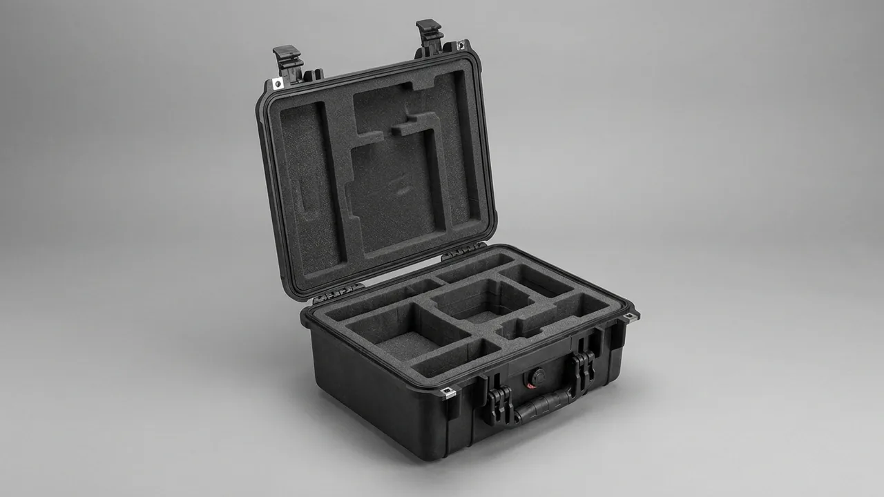
A heavy duty case is not an ordinary enclosure enlarged by a scale factor. As payload mass rises, base bending, caster impacts, forklift contact, lifting imbalance, and multi-tier stacking interact. A high or offset center of gravity also changes stability at thresholds, on slopes, and during turns. A shell that survives a static bench load may still suffer caster pullout, fork-pocket buckling, torn lifting attachments, an opening seal frame, or payload supports punching through the liner during real handling.
JUNZHIJIA defines heavy-duty protection as a continuous load path that transfers payload force through cradles and the base into a structural system, then safely releases it through casters, forklift pockets, lifting points, or stacking nodes under controlled handling geometry. This guide links structural design to caster boards, fork interfaces, lifting points, sling angles, stacking tiers, center-of-gravity marking, verification, and batch acceptance.
Table of Contents
- Build a load map from payload and logistics data
- Create continuous high-load paths through the case
- Engineer the base, load boards, and caster interfaces
- Size forklift pockets and prevent incorrect entry
- Control lifting points, sling angles, and off-center loading
- Define stacking tiers through long-duration stability
- Combine shell materials, wall sections, and reinforcement
- Mark the center of gravity and verify mobile stability
- Coordinate closures, sealing, and pressure equalization
- Support, cushion, and restrain heavy equipment
- Verify structural and handling performance
- Control customization, production, and supplied documents
- Frequently Asked Questions FAQ
- Conclusion and Related Reading
Build a Load Map from Payload and Logistics Data
Heavy-case design starts with a load map rather than a single payload number. The map records equipment mass, accessories, three-axis center of gravity, support feet, approved lifting surfaces, fragile projections, removal direction, and changes between operating configurations. The logistics side should identify travel distance, slopes, floor joints, threshold height, turning clearance, forklift models, tine dimensions, rack or pallet interfaces, lifting equipment, rigging hardware, vehicle vibration, and warehouse stacking. A statement such as 300-kilogram capacity is incomplete unless it explains whether that mass rests uniformly, enters through four concentrated feet, or crosses a threshold on casters.
Every handling mode has a load entrance and exit. During floor storage, payload force moves through its cradle, base, and feet into the floor. During rolling, floor shock travels in reverse through wheels, mounting plates, and the base frame. During forklift handling, two narrow support bands lift the entire assembly. During crane lifting, attachment points and slings form a spatial force system. During stacking, upper weight enters through localized registration features. Placing these paths on one drawing often shows that a bottom corner performs several jobs: it may support a caster plate, terminate a fork channel, and receive a stacking reaction.
Requirements should distinguish working, dynamic, and proof loads. Working load defines routine use. Dynamic factors represent threshold impact, braking, steering, and crane acceleration. Proof load confirms a production margin without necessarily qualifying the product for operation at that higher load. Safety factors must reflect uncertainty, failure consequence, material behavior, and applicable requirements rather than an arbitrary universal number. Communication or emergency payloads also need post-handling functional criteria. Common toolbox types and selection can help define the starting architecture, but the final rating belongs to the verified configuration.
| Input category | Required data | Primary design effect |
|---|---|---|
| --- | --- | --- |
| Payload configuration | Mass, support points, center of gravity | Base frame, cradle, stability markings |
| Rolling route | Slope, threshold, gap, turn radius | Wheel size, caster board, braking, overturning |
| Forklift fleet | Tine width, thickness, spacing, direction | Pocket clearance, reinforcement, entry control |
| Lifting method | Point count, hardware, travel height | Attachments, sling geometry, imbalance cases |
| Stacking plan | Loaded tiers, duration, temperature | Compression nodes, frame, and creep limits |
Create Continuous High-Load Paths Through the Case
A heavy payload should not rely on an isolated plastic floor. Equipment feet should align wherever possible with crossed structural ribs, bottom beams, or the coverage of a distribution plate. These regions should then align with external skids, casters, fork channels, or stacking supports. Good paths are short, continuous, and reasonably balanced. Where they must pass around an opening, a closed rib, broad flange, or metal spreader should redirect the force. Free-body diagrams for each handling state reveal payload-foot reactions, base bending, caster shear, fork-bearing pressure, and seal-frame torsion.
The lower shell, sidewalls, perimeter frame, and lid interact under load. Payload inertia bends the floor and pulls the walls inward or outward. The walls use the closed frame to resist racking, while hinges and latches retain alignment. In a deep-lid or removable-cover design, the cover may become a primary stacking member. Finite element analysis should model concentrated feet, realistic contacts, fastener preload, and temperature-adjusted material behavior. It should report displacement and connector reactions, not merely a colorful peak-stress image.
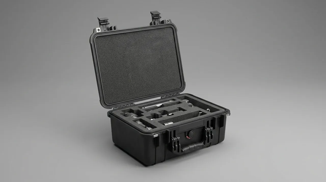
Abrupt stiffness changes deserve attention. Failure frequently begins where a distribution plate ends, a fastener hole lies too near an edge, a plastic beam is cut by a pocket, or a lifting insert connects to only one thin surface. Loads should spread progressively through radiused transitions and overlapping support zones. Strain or displacement measurements around payload feet, plate edges, caster mounts, and the seal frame can validate the model. If one caster carries far more than its expected share, investigate base flatness, center-of-gravity offset, assembly gap, and plate deformation before merely selecting a larger caster.
Engineer the Base, Load Boards, and Caster Interfaces
Catalog caster capacities cannot simply be added to determine case capacity. Four casters marked for 150 kilograms each do not prove a 600-kilogram case rating. An uneven floor can leave only three wheels carrying effective load. An offset center of gravity can place a much larger reaction at one corner. Threshold crossing, hard braking, and steering add shock and side load. Wheel diameter, tread, bearing, swivel race, bracket, mounting plate, fasteners, and the shell all participate. A conservative analysis checks the most highly loaded wheel under three-point support and an appropriate dynamic factor.
A load board spreads the concentrated caster reaction into a wide portion of the base. Board thickness, folded edges, bolt pattern, bearing washers, and contact with the molded floor must be developed together. Four small washers inside a thin wall can allow bearing crush or pull-through. Conversely, an extremely stiff metal board with a sharp edge can create a new crack origin where it ends. A radiused outline, staged plastic ribs, full contact, and locking fasteners help wheel shock enter the base structure gradually. Dissimilar metals and wet service require compatible coatings or isolation.
Caster geometry controls stability and maneuverability. A wider wheel track usually increases resistance to overturning, while projecting wheels consume aisle clearance and attract collision. Moving wheels inward protects them but narrows the stability polygon. Two fixed plus two swivel casters, four swivels with brakes, or directional locks suit different routes. Brakes should be reachable without placing an operator's foot under the load and should not bind when the loaded base flexes. Ideas in industries using trolley toolboxes help frame mobility needs, but the completed heavy case must be evaluated at actual gross mass.
| Caster-system factor | Main risk | Verification method |
|---|---|---|
| --- | --- | --- |
| Individual rating | Ignores three-wheel support and offset mass | Measure wheel reactions on level and uneven fixtures |
| Plate edge | Stiffness jump cracks the polymer floor | Inspect strain and damage after loaded threshold cycles |
| Fastening | Loosening, bearing crush, or pull-through | Apply torque witness marks and recheck after cycling |
| Wheelbase and diameter | Overturning or excessive threshold force | Test slopes, turns, gaps, and specified obstacles |
| Brake configuration | Insufficient holding or accidental release | Hold rated load on the maximum approved slope |
Starting force, steady rolling force, and obstacle force are different measurements. A small hard wheel may roll easily on a smooth floor yet demand extreme force at a cable cover. A softer tire lowers vibration and noise but can develop greater rolling resistance and heat under sustained mass. Instrumented pull tests and measured accelerations at the payload help select a practical compromise rather than relying on wheel diameter alone.
Size Forklift Pockets and Prevent Incorrect Entry
Forklift pockets must match the fleet that will actually handle the case. Required inputs include tine width, thickness, edge radius, adjustable spacing range, tip taper, carriage height, approach visibility, and any fork-mounted sensors or extensions. Pocket height must include manufacturing variation, loaded base deflection, floor irregularity, and normal tine pitch. Pocket width should tolerate entry without allowing uncontrolled transverse motion once lifted. If entry is permitted from only one direction, labels and physical blocking should discourage insertion from an unsupported side.
During lift, two narrow bands replace broad floor support. Their spacing controls base span and bending moment. The pocket roof needs local bearing resistance, and pocket ends must distribute shear and bending into longitudinal and cross members. An opening must not abruptly cut the strongest bottom-corner or caster-board rib. Closed or partly closed channels, wear plates, radiused guides, and reinforced end nodes can preserve continuity. Because a tine tip can be driven into the end wall, the termination should resist penetration and maintain separation from the payload.
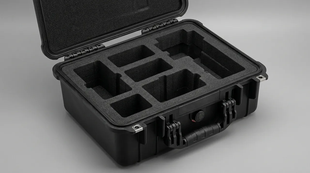
Verification means more than confirming that the tines fit. A rated-load case should be entered from each approved direction, lifted, held, translated slowly, turned, braked, and set down. Observe base deflection, lateral slide, contact marks, seal-frame twist, payload movement, and damage at pocket roofs or ends. For long cases, confirm that minimum insertion extends beyond the center-of-gravity projection with sufficient margin. A visible minimum-insertion line helps operators recognize an incomplete lift.
Pockets collect water, grit, and cleaning residue. They should drain and permit inspection. Metal wear surfaces need corrosion protection, and open edges must not create hand hazards. Maintenance instructions should state wear, deformation, cracking, and fastener limits. If several forklift models differ significantly, the handling document should list allowable tine envelopes and prohibited spacing rather than assuming the largest opening makes every arrangement safe.
Misuse can also come from pallet jacks whose short or articulated forks load the pocket differently. Approval for forklift tines does not automatically approve every lifting vehicle. Each interface needs adequate insertion depth, contact location, and clearance through the full steering movement. Where accidental entry could damage wheels or a valve, guards and clear directional markings are more dependable than a warning hidden in a manual.
Control Lifting Points, Sling Angles, and Off-Center Loading
A lifting point must connect to the primary structure, not only to a cover, carry handle, or single wall. The design should define point count, coordinates, rated working load, connector type, load direction, and required case configuration. A nominal four-point lift is rarely perfectly equal. Sling-length tolerance, attachment height, case torsional stiffness, hook position, and an offset center of gravity redistribute forces. Calculations must include unequal sharing and determine whether one or two points can experience substantially higher reactions.
Sling angle has a decisive effect. As a sling leg approaches horizontal, its tension rises and its inward horizontal component squeezes the case. The approved plan should specify a minimum angle from horizontal or maximum angle from vertical, using one unambiguous convention. Long enough slings or a spreader beam keep legs more nearly vertical and reduce compression. A gross-weight label alone cannot control this geometry. Shackles, hooks, pins, and eye holes also need compatible diameters and bearing radii; a small pin can damage a large but thin eye.
Attachments require sufficient back plates, fastener edge distance, insert strength, weld quality, and load spreading into beams. Around each point, provide room to install rigging without trapping fingers or rubbing a latch, seal edge, valve, or connector. If lifting is safe only with the lid closed and every latch engaged, prominent instructions and design error-proofing should support that rule. The structure must never assume a user will lift from ordinary ergonomic handles merely because they are easy to reach.
Prototype verification may include a specified proof load held for a defined period, followed by low-height movement, controlled start-stop, and credible imbalance cases. Measure permanent attachment movement, local strain, case twist, latch-force change, and payload displacement. Lifting tests demand professional exclusion zones and approved equipment. The case supplier can state verified interface capability, but qualified personnel at the site must approve the lift plan for the crane, rigging, environment, and governing rules.
Inspection remains part of the rating. Before a lift, examine eyes, plates, welds, pins, fasteners, corrosion, and labels. A previous forklift impact or transport drop may have damaged an attachment even though the last lift succeeded. The manual should define removal-from-service criteria and whether a repair is permitted. Unauthorized drilling or welding close to a lifting path can invalidate the original verification.
Define Stacking Tiers Through Long-Duration Stability
Stacking tiers must be calculated from loaded mass, interface geometry, duration, temperature, and dynamic environment. The bottom case supports every loaded unit above it. If each case has a gross mass of 250 kilograms, the bottom unit in a four-high stack carries approximately 750 kilograms from the upper units before dynamic allowance. Local reactions are seldom equal because of load variation, floor slope, molded tolerances, and placement error. Vehicle stacking adds vertical acceleration and lateral shear, so warehouse and in-transit tier limits may differ.
Upper feet should land on reinforced nodes of the lower lid. Recesses or interlocks provide lateral registration while retaining clearance for placement, separation, drainage, and tolerance. A very small contact can crush a node; overly deep engagement can damage an edge when the case lands slightly skewed. Similar-looking sizes are not automatically compatible. The analysis of stackable toolbox height limits illustrates why geometry and stability, not appearance, determine permissible height.
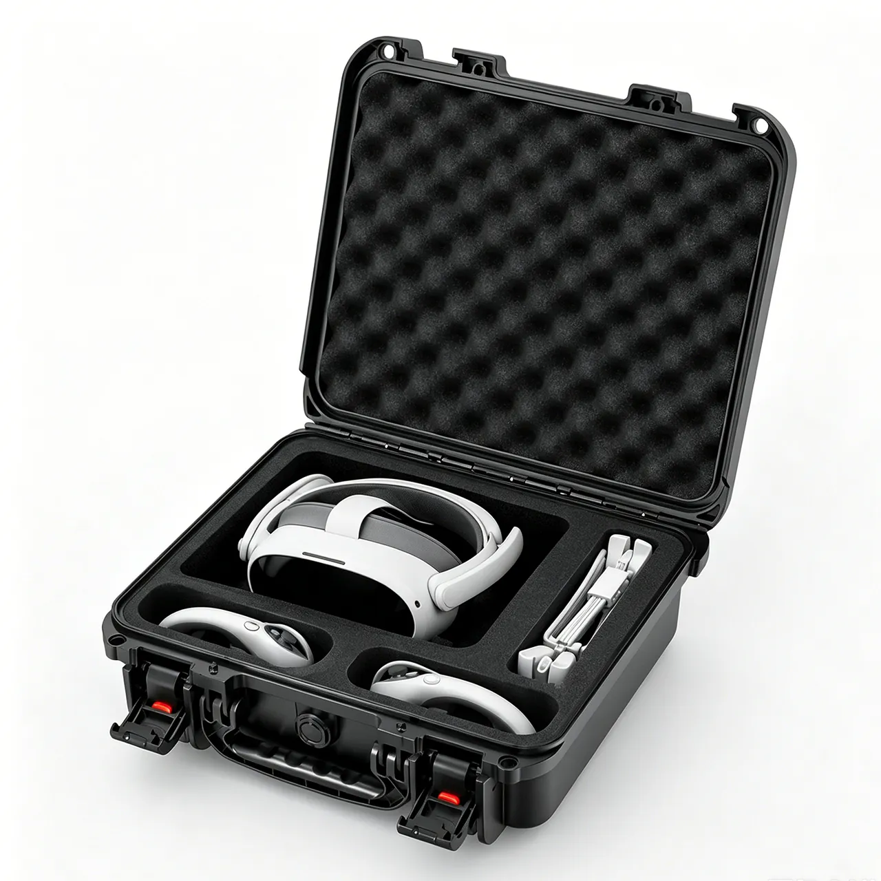
Polymer creep makes time and temperature essential. A short room-temperature proof demonstrates immediate strength but not weeks in a hot warehouse. Testing should apply the equivalent upper-tier load at rated payload and worst justified temperature. Measure immediate displacement, change throughout the hold, residual deformation after unloading, and recovery. Recheck latch force, seal witness, frame fit, and the ability to stack again. A permanent crushed node or shifted frame can threaten both stability and environmental sealing.
Labels should state maximum gross mass per case, maximum loaded tier count, compatible models, and distinctions between storage and transport. If empty-case stacking has a different limit, identify it separately. Operational controls should prevent a heavy case from being placed on a lighter unit, bridging incompatible lids, stacking on a slope, or leaving a mobile stack unrestrained. Structural capacity cannot correct an unstable floor or careless placement.
Stability also depends on overall center of gravity and footprint. Even when every node remains below its compression limit, a tall narrow stack can overturn under lateral acceleration. Transport restraint calculations and rack interaction may therefore govern before vertical strength. Stacking approval should address compression, shear registration, global overturning, and restraint as separate checks.
Combine Shell Materials, Wall Sections, and Reinforcement
Large heavy-load enclosures may use modified polypropylene, polyethylene, or other engineering polymers combined with rib networks, local double walls, metal load boards, and structural frames. Selection should compare flexural modulus, impact toughness, creep, cold-notch behavior, ultraviolet stability, chemicals, density, and manufacturing process. Rotational molding can create large continuous shells with its own wall-variation logic. Injection molding offers repeatable details and integrated features but introduces long-flow, weld-line, and tooling considerations. The two processes should not be rated by the same nominal thickness assumption.
Thickness is not the sole capacity measure. The floor resists concentrated equipment feet, sidewalls handle racking, and the lid and perimeter take stack and closure force. Hat sections, closed ribs, turned edges, and distribution plates increase section inertia efficiently. Uniform mass added to low-stress panels may deliver little benefit. When a metal subframe is combined with a polymer shell, attachments must address differential thermal expansion, fretting, and moisture. A hard metal edge must not slowly wear through a moving plastic surface.
Rib endings, holes, inserts, and section transitions need generous radii and staged stiffness. A long flow path may leave an injection-molded beam incompletely packed or place a weld line near a caster mount. Rotationally molded parts require wall mapping around corners, inserts, and deep geometry. First samples should receive thickness mapping, flatness checks, and load correlation. Minimum measured sections, not ideal CAD values, belong in structural calculations.
Environmental exposure applies to the system. Guidance on outdoor case rain and humidity helps define moisture risks, but metal plates, caster brackets, lifting eyes, fasteners, labels, adhesives, and gaskets must be evaluated together. Corrosion may weaken a hidden connection while the polymer exterior remains visually unchanged. Drain paths should not direct water into a bonded plate or closed crevice.
Material source, compound, color concentrate, allowable regrind, metal grade, coating, and critical process windows require control. A resin substitution, caster-board thickness change, mold repair, or different insert process may alter structural performance. The change plan should link each affected load path to dimensional, proof, handling, or environmental retesting rather than treating all changes as cosmetic.
Mark the Center of Gravity and Verify Mobile Stability
The center of gravity should be established for every approved payload configuration. Equipment CAD mass properties provide a useful prediction, but multi-point weighing confirms the horizontal projection. Controlled tilt or other engineered measurement can help establish height. Accessories, spares, consumables, sliding drawers, and removed modules may shift the result. Markings must therefore correspond to a defined loading diagram rather than an empty shell.
At least two adjacent outer faces should show the center-of-gravity projection or direction so forklift and lifting personnel can interpret it from different approaches. Gross mass, upright orientation, forklift entry, minimum insertion, and approved lifting points should be nearby but visually distinct. A center symbol casually placed at the geometric middle creates false confidence. If configurations differ greatly, use configuration-specific diagrams, replaceable labels, or physical rules that prevent an unapproved layout.
Rolling stability depends on center-of-gravity height and the wheel support polygon. A transverse slope, turn, or wheel strike creates an overturning moment. A high-center case may be statically stable on level ground yet rotate abruptly when one caster meets a joint. Analysis should compare restoring and overturning moments in each direction, with reasonable dynamic allowance. Testing at gross mass should include starting, straight travel, specified turns, threshold crossing, controlled stopping, and parking on the maximum approved slope.
Human factors complete the system. Push and pull handles should let an operator apply force at a natural height without grabbing the cover, latch, or valve. Starting force, continuous force, and obstacle force need separate limits. When mass exceeds suitable manual handling, instructions should require mechanical assistance instead of adding multiple ambiguous handholds. Brakes must be reachable without standing downhill of the case or putting a foot under it.
Markings need durable contrast and abrasion resistance. Instructions should include brake application before opening, prohibition on opening across a slope, full fork insertion, sling clearance, and safe parking. Labels help users respect a verified design envelope; they cannot compensate for a narrow wheelbase, inadequate brakes, or a payload assembled outside the approved arrangement.
Coordinate Closures, Sealing, and Pressure Equalization
Large frames are sensitive to racking. Latch number and placement must follow frame stiffness and gasket-pressure distribution, not visual symmetry alone. Excessive preload near a latch can over-compress that segment while the middle of a long side remains unloaded. Pressure-sensitive media, transfer witness, or gap mapping can show compression around the perimeter. Hinges must carry a large cover and opening shock, often with check straps, gas springs, or mechanical stays to prevent a falling lid and to avoid placing the full open-lid moment into small hinge roots.
The gasket groove requires controlled section, squeeze, fill, joint location, and corner transitions. Fork lifting, single-wheel threshold travel, or an imbalanced lift can twist the frame temporarily. An ingress claim should therefore consider whether testing occurs only on a new empty case or after specified handling. For an IP65 or IP67 target, the procedure needs a named standard, payload condition, valve and port states, conditioning sequence, and acceptance rule. Differences among IP65, IP66, and IP67 help clarify boundaries but cannot replace model-specific verification.
A pressure-equalization valve helps large-volume cases respond to altitude and temperature without excessive opening force or seal stress. Flow capacity should suit volume and rate of change. Location should avoid pooled water, sling abrasion, forklift contact, labels, and internal foam blockage. The membrane needs protection from mud, oil, and aggressive cleaning. Thread, seal, torque, and service replacement all affect enclosure integrity.
Closures also need operational error control. Large cases may require several latches that are difficult to see from one position. Sequential markings, contrasting closed-state indicators, or interlocks can reduce partial closure. If the case must never be rolled, forked, or lifted while open, warnings should appear near the handling interface. Closure checks are part of the pre-move inspection, not merely a waterproofing step.
Support, Cushion, and Restrain Heavy Equipment
A massive payload should not be surrounded only by soft foam. Its support system must use approved structural locations and transfer reaction into the reinforced base. High-density foam blocks, machined cradles, elastomeric isolators, rails, or a metal-composite deck may be combined. Small bearing areas can crush foam or bottom it during impact, while excessively large areas may keep stress too low for useful cushioning. Selection should use payload surface loading, allowable acceleration, available stroke, and measured dynamic response.
High-center payloads require strong lateral restraint. Forklift braking, vehicle cornering, and case inclination create side forces even without a formal drop. Straps, beams, brackets, or location blocks should connect approved structural points, not displays, knobs, thin covers, or delicate connectors. Webbing paths need protection from sharp edges and a repeatable tension method. Error-proof routing and positive retention reduce the chance that an operator returns the equipment without securing one restraint.
Loose accessories become secondary projectiles. Cables, batteries, tools, and spares need separate cavities or tie-downs. Removal planning may require a small hoist, slide rail, ramp, or lifting fixture. The case edge should not become an improvised step, and forklift tines should not directly push the instrument. Principles used in cushion liner cases remain relevant, but heavy equipment adds concentrated reactions, restraint strength, and mechanical-removal requirements.
Lid foam normally controls bounce rather than carrying large continuous compression. Excessive top pressure can damage the instrument and distort the seal frame. Relief must protect screens, controls, antennas, and optical features. Where the equipment includes service doors or drawers, confirm that the cradle cannot release or tip when one component extends.
After handling tests, inspect payload position, support imprints, isolator travel, fastening torque, strap abrasion, accessory movement, and foam set. If calibration matters, correlate measured acceleration and displacement with functional results using approved equipment or a representative simulator. Foam grade, lot, cutting direction, adhesive, isolator batch, and installation coordinates belong in controlled production records.
Verify Structural and Handling Performance
A verification matrix should cover static capacity, dynamic handling, environmental exposure, and payload function. Establish dimensional, caster-reaction, center-of-gravity, latch-force, and equipment baselines first. Then conduct relevant rolling, threshold, slope-hold, forklift, lifting, stacking, vibration, impact or tip, thermal, and ingress tests. Finally, repeat the baselines. The sequence may represent cumulative service, while separate specimens can isolate especially destructive modes. If a transport standard is cited, record the exact procedure, level, load, and deviation.
| Verification | Key records | Unacceptable outcome |
|---|---|---|
| --- | --- | --- |
| Loaded rolling and thresholds | Force, wheel reaction, plate strain, torque | Mount separation, shell crack, loss of control |
| Forklift cycles | Insertion, deflection, slide, pocket wear | Buckling, tine penetration, case instability |
| Lift hold and imbalance | Point reaction, twist, permanent movement | Cracked eye, pulled connection, latch release |
| Hot stacking | Displacement over time and residual set | Crushed nodes, frame mismatch, seal interruption |
| Vibration and impact | Payload response, restraints, accessory motion | Payload escape, foam bottoming, functional drift |
| Sealing and thermal cycling | Ingress, valve state, operating force | Ingress beyond criteria or unusable closure |
Acceptance criteria must be agreed before testing. They should include permanent-deformation limits, zero-crack zones, allowed fastener-torque change, payload acceleration, pocket wear, latch-force range, attachment movement, and ingress definition. Cosmetic scuffing may be graded separately, but whitening at a structural connection, bearing crush, weld movement, or insert displacement is not ordinary appearance. Raw data, load certificates, calibrated equipment identities, images, and specimen numbers provide traceability.
When failure occurs, follow the path of force. A caster-area crack may begin at a plate edge, arise from an offset center of gravity, result from a floor impact, or reveal an assembly gap. Fork-pocket damage may come from unapproved tine spacing rather than insufficient resin. Locate the origin, reconstruct load history, inspect manufacturing evidence, and then classify the issue as requirements, architecture, detail geometry, material, process, assembly, operation, or test setup.
Correct the root cause and repeat affected regression tests. Uniform wall thickening can add mass while moving failure into another joint. A longer load board, revised rib termination, controlled fastener stack, clearer fork-spacing limit, or altered sling plan may be more effective. Verification closes only when the revised production-representative configuration satisfies the original function and all linked interfaces.
Control Customization, Production, and Supplied Documents
A controlled heavy-case program progresses through requirement freeze, structural concept, engineering mockup, tooled sample, and production approval. Requirement freeze captures all payload configurations, maximum gross mass, center of gravity, handling route, forklift and rigging data, stacking, environment, sealing, and acceptance matrix. An engineering sample verifies access, support locations, wheel track, pocket clearance, rigging space, and removal method before tool commitment. A tooled sample reveals actual thickness, shrinkage, warpage, connection behavior, and surface condition.
OEM and ODM delivery needs a controlled bill of materials and critical-characteristic list. Shell compound, frame, caster board, wheels, fasteners, lifting eyes, latches, gasket, valve, cradle, straps, labels, and supplied documents require specifications and revisions. Batch inspection may sample appearance, dimensions, torque, fit, and operation. Load, forklift, lift, stack, impact, and ingress properties can use first-article, periodic, and change-triggered evidence. A major tool repair or structural supplier change cannot be released by color inspection.
JUNZHIJIA can use equipment geometry and logistics flow to configure shell structure, base frame, caster plates, forklift pockets, lifting points, stacking nodes, cradles, and center-of-gravity markings. Tooling, identification, OEM or ODM details, and batch consistency can be managed as a connected project. The supplied package may include released drawings, material statements, load and test records, inspection results, rigging restrictions, maintenance criteria, and packing data.
Operating documents should state maximum gross mass, approved loading diagram, center of gravity, forklift entry and minimum insertion, lifting points and minimum sling angle, maximum tiers, brake use, inspection intervals, and removal-from-service conditions. A deformed eye, cracked fork pocket, loose caster board, severely shifted frame, or unreadable structural label should place the case in quarantine until competent evaluation.
Change management continues after approval. Resin, plate gauge, caster model, fastener grade, lifting hardware, foam, mold condition, or process changes may affect a load path. The control plan should map each change to notice, sample submission, dimensional comparison, proof test, or requalification. Retained master samples and baseline measurement records help separate genuine drift from permissible cosmetic variation.
Frequently Asked Questions FAQ
Q: Is the sum of four caster ratings the maximum payload of a heavy duty case?
A: No. Catalog ratings normally assume specified speed, temperature, smooth flooring, mounting, and load distribution. A real case can rest effectively on only three wheels when the floor is uneven, while an offset center of gravity greatly increases one corner reaction. Threshold crossing, braking, and turning add dynamic and lateral forces. The complete rating must check wheel, bracket, swivel, mounting board, fasteners, polymer floor, base frame, and payload cradle together. Analysis should use a credible three-point support case and a dynamic factor suited to the route. A production-representative sample then needs gross-load tests for individual wheel reactions, starting force, steering, slope holding, obstacle crossing, and braking. Afterward, inspect plate strain, bolt witness marks, hole bearing, looseness, and shell cracking. The weakest verified interface determines capacity. Adding four printed caster values ignores distribution, impact, structural attachment, and the possibility that a wheel's catalog conditions differ from field service. Documented route conditions and maintenance limits must accompany the rating so later operators preserve those assumptions.
Q: Why must forklift tine spacing and minimum insertion depth be specified?
A: The two tines become narrow structural supports during a lift. Their spacing sets the unsupported base span and bending moment, while insertion depth determines whether support extends beyond the center-of-gravity projection. Tines that are too close can overload the middle of the base. Tines that are too far apart can contact unreinforced edges. Incomplete insertion can leave the center of gravity outside the support region, allowing forward rotation or slide. Thickness, taper, up-angle, edge radius, and floor variation also govern pocket clearance. Drawings and labels should therefore show permitted spacing, entry direction, minimum insertion line, and prohibited zones. Loaded verification should include entry, raising, holding, slow translation, turning, braking, and placement, with inspection of roof contact, end penetration protection, base deflection, frame twist, and payload movement. Approval for one forklift arrangement does not automatically include a pallet jack or another fleet with different geometry. Measured contact marks should confirm that the approved tine surfaces, not pocket edges, carried the load.
Q: Do four lifting points each carry exactly one quarter of the case weight?
A: Equal sharing cannot be assumed. Sling-length tolerance, attachment elevation, hook position, case torsional stiffness, and an offset center of gravity change the reactions. One or two points can carry substantially more than a quarter, particularly before the case settles into its suspended orientation. Calculations should examine uneven sharing, dynamic start-stop factors, and the least favorable load direction. Each eye, pin, backing plate, fastener, weld, and structural connection must have a continuous path into the main frame. Sling geometry matters equally: as a leg approaches horizontal, tension and inward compression rise rapidly. The operating document should define a minimum angle using a clear reference, and a spreader beam may be required. Prototype proof holding, controlled low-height motion, and credible imbalance tests should measure permanent set, local strain, twist, closure change, and payload movement. Qualified lifting personnel must still approve site-specific cranes, rigging, exclusion zones, and environmental conditions. Pre-lift inspection must also confirm hardware identity, engagement, condition, and the required closed-case configuration before tension is applied.
Q: How is the maximum stacking tier count for heavy duty cases determined?
A: Begin with the gross loaded mass of every unit above the bottom case, then include distribution error, placement tolerance, floor slope, transport acceleration, temperature, and load duration. Upper feet must land on reinforced lower-case nodes that transfer compression through the frame and base. Similar outer dimensions do not establish compatibility. Polymer creep makes a brief room-temperature press inadequate for long warehouse storage. A representative test should apply the equivalent upper-tier load at the worst justified temperature and specified time, recording initial displacement, change during the hold, residual set after unloading, and recovery. Closure force, gasket witness, registration features, and repeat stacking should then be checked. Global stability also needs center-of-gravity, footprint, lateral acceleration, and restraint analysis; compression capacity alone cannot prevent overturning. Labels should distinguish loaded and empty limits, warehouse and transport tiers, compatible models, maximum gross mass, and environmental restrictions so operators can reproduce the verified arrangement. Periodic inspection must also detect cracked nodes, permanent lean, and worn registration features before continued stacking.
Q: How should center-of-gravity markings support safe handling?
A: The location should come from approved payload data and multi-point weighing, not from the geometric center of an empty shell. At least two adjacent faces should show the projection or direction so forklift and lifting personnel can interpret it from different approaches. Gross mass, upright orientation, fork entry, minimum insertion, and lifting points should appear nearby with distinct symbols. Accessories, drawers, spares, batteries, and consumables may move the center of gravity, so materially different configurations need separate loading diagrams, labels, or physical restrictions. The design team should also use center-of-gravity height and wheel track to calculate overturning boundaries for slopes, turns, braking, and obstacles, then verify them at gross mass. Markings must remain legible after abrasion and cleaning. They guide the operator toward the verified handling plan but cannot compensate for an inadequate wheelbase, insufficient brakes, short fork insertion, incorrect sling geometry, or a payload assembled outside its approved arrangement. A configuration code beside the symbol helps crews match the visible mark to the current loading diagram.
Q: Is high-density foam alone enough to secure heavy equipment?
A: Not always. Heavy equipment can impose high static stress on small foam areas, leading to compression set during storage and bottoming during impact. The cradle should first support approved structural points on the equipment and transfer their reactions into the reinforced case base. High-density foam, shaped supports, elastomeric isolators, rails, straps, or a metal-composite deck may be combined. A high center of gravity requires lateral restraint for forklift braking, vehicle turns, and inclination. Restraints must not load displays, controls, lenses, connectors, or thin covers, and their routing should resist loosening and abrasion. Foam selection needs actual surface loading, usable travel, environmental conditioning, and dynamic response rather than density alone. Cables, batteries, tools, and spares require separate retention so they do not become projectiles. Face, edge, corner, vibration, braking, and access trials should verify movement, cushion strain, fastener torque, strap condition, payload function, and repeatable operator installation. Inspection criteria should define allowable compression set, abrasion, loosening, and replacement intervals for every restraint component.
Q: Why should ingress protection be reassessed after heavy-case handling tests?
A: A large perimeter can twist during fork lifting, single-wheel threshold crossing, imbalanced rigging, or off-center stacking. Even if the shell seems to recover visually, latch alignment and gasket compression may have changed. An IP67 result from a new, unloaded, stationary sample may therefore omit an important service interaction. The project should define load state, valve and port configuration, conditioning, exposure, and acceptance, then sequence repeated ingress checks after handling events when risk justifies them. A contaminated groove, trapped cable, field-drilled interface, replacement valve, partially closed latch, or damaged gasket can also invalidate the original condition. The rating applies only to its defined water depth, duration, orientation, and procedure, not unlimited hydrostatic or dynamic pressure. Routine inspection should assess gasket cuts, compression set, witness continuity, frame gap, latch force, and valve cleanliness. System integrity depends on the assembled, handled enclosure, not isolated component labels. The post-handling result should be compared with the original baseline to reveal progressive frame or closure change before visible leakage becomes severe.
Q: Which load-bearing areas deserve priority during batch acceptance?
A: Priority areas include base structure under payload feet, distribution-board edges, caster holes and torque, fork-pocket roofs and terminations, lifting-point back plates, stacking nodes, perimeter frames, latch mounts, and hinge supports. Dimensional checks should cover base flatness, pocket clearance, allowed tine spacing, lifting coordinates, wheel track, seal groove, and usable cavity. Functional checks should include loaded rolling, braking, fork fit, closure force, payload support, restraint installation, and correct markings. Destructive capacity, lift, stack, impact, and ingress tests are not practical on every unit, so the plan should combine first-article evidence, lot sampling, periodic type tests, retained samples, and change-triggered requalification. Resin, plate stock, caster, lifting hardware, fastener, cradle, supplier, or tooling changes must be reviewed against affected load paths. Acceptance records should identify lot, specimen, drawing revision, calibrated equipment, method, values, deviations, and reviewer so a later field observation can be traced to production evidence. Photographing witness marks and measured structural interfaces further strengthens comparison between retained samples and field returns.
Conclusion and Related Reading
JUNZHIJIA integrates load paths, caster boards, fork pockets, lifting geometry, stacking limits, custom cradles, OEM or ODM options, markings, and traceable documentation into a heavy-case system with measurable handling boundaries.
Related Reading