

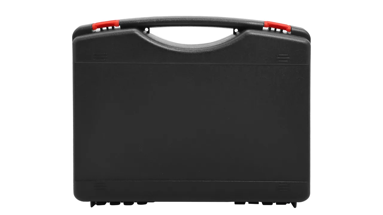
A gear hobbing machine is one of the most temperamental pieces of heavy equipment in the gear-cutting chain. The bed and column look solid, yet the tolerances that decide gear quality live in a few mirror-ground taper surfaces and a worm pair measured in arc-seconds: hob spindle radial runout is typically held under 3 μm and worm backlash is often a few dozen arc-seconds. During overhauls, factory shipping or export delivery, these parts must survive thousands of kilometers of road vibration, port lifting and humid containers.
The JUNZHIJIA principle: locate the accuracy datum surfaces and runout tolerances first, then work backward to case design through three layers — rigid support, sealed isolation and micro-vibration damping. Packaging for hobbing components cannot follow a generic toolbox template. You must identify which surface is the datum, which must not be struck, which must not be scratched and which must not see moisture, then translate each constraint into a specific liner cavity and fixing point. This article works through the drive chain component by component and provides material comparisons, sealing grades, test verification and acceptance criteria.
Table of Contents
- Hobbing Machine Drive Chain and Component Protection Challenges
- Hob Spindles: Protecting Radial/Axial Runout and Taper Fits
- Indexing Worm Gears & Worktables: Preserving Indexing Accuracy
- Tool Heads, Tailstocks and Column Guideways
- Servo Motors, Encoders and Electrical Controls
- Geometric Accuracy Retention and Micro-Vibration Protection
- Rust Prevention, Scratch Protection and Cleanliness Control
- Case Shell Materials and Structural Design
- Sealing Ratings: IP65 / IP67 with IEC 60529 and GB/T 4208
- Cushioning Liners: EPE / EVA / PE / IXPE with Compartmentalization
- Latches, Hinges, Pressure Equalization Valves and Stacking Loads
- Temperature, Humidity, Salt Spray and Transport Testing
- Customization, OEM/ODM and Acceptance Criteria
- Frequently Asked Questions FAQ
- Conclusion and Related Reading
Hobbing Machine Drive Chain and Component Protection Challenges
Gear hobbing cuts a tooth profile by running a hob and a workpiece through a fixed generating ratio, and the resulting accuracy traces through three chains: the spindle chain (arbor, hob spindle, bearings), the indexing chain (worm pair, worktable, differential) and the rigidity chain (column, tool head, tailstock, guideways). Weights vary from a few-kilogram encoder to cast iron beds above two tonnes, yet all share one property: every tolerance hangs on a handful of precision mating surfaces.
The difficulty is that the shapes conflict: long shafts need axial suspension, heavy castings need ground-level restraint, precision tooth surfaces need non-contact fixing, and electronics need antistatic, moisture-proof surroundings — four demands met in one case, which is why hobbing machine packaging rests on compartmentalization plus matched liner materials.
| Component | Key accuracy feature | Typical transport failure | Protection focus |
|---|---|---|---|
| --- | --- | --- | --- |
| Hob spindle (arbor) | Radial runout ≤3 μm, axial play ≤2 μm | Taper scoring, bearing seat dents | Taper cap, axial limit, suspended support |
| Indexing worm pair | Backlash in arc-seconds, contact pattern | Mating surface damage, tooth rust | Tooth wrap, VCI protection, separate cavity |
| Worktable | Face runout, T-slot location, taper bore | Face scratching, bore deformation | Soft face pad, bore plug |
| Tool head and arbor | Mounting face flatness, rotation accuracy | Mounting face damage, arbor bending | Face film, axial cradle |
| Column and guideway | Scraped face flatness, straightness | Scraped face scratching, rust spots | Cover protection, non-contact limit |
| Servo motor and encoder | Shaft runout, disc accuracy | Disc fracture, shaft bending | Isolated damping cavity, antistatic liner |
Hob Spindles: Protecting Radial/Axial Runout and Taper Fits
The hob spindle is the accuracy core of a hobbing machine. One end connects to the hob through a taper while the mid-section is carried by high-precision bearings inside the tool head. Common interfaces include Morse tapers, 1:10 short tapers, 7:24 tapers and HSK-type shanks, and taper contact is generally specified at 85% or better — a single hard chip pressed into the taper can push it below the threshold.
The most common shipping mistake is treating the spindle as an ordinary shaft and laying it flat. The correct approach rests the shaft on two V-shaped EVA cradles on the rigid sections near the bearing seats, covers the taper end with a dedicated cap lined in PE film, and uses an axial stop on the other end that limits end-play while retaining 1–2 mm of elastic clearance. The cap does two jobs at once — it blocks impact and keeps the taper free of chips.
Runout retention depends on whether the shaft can move relative to the case, so fixing should avoid both rigid clamping and complete freedom. The recommended pattern is two-point radial location plus one elastic axial constraint: two V-blocks set radial position, one elastic block sets axial position, and under impact the shaft shifts elastically rather than sliding. For quick-change interfaces with pull studs or holders, the holders belong in a separate compartment so they cannot strike the taper. General support and bearing-seat logic for this shaft class is described in CNC Spindle Cases: Spindle & Bearing Assembly Protection.

For hob cutters shipped in batch, the hob and arbor are usually packed separately: hob teeth are cutting edges, and any chipped tip degrades profile accuracy, so hobs stand upright or are held by tooth-groove blocks with the edges touching no hard surface.
Indexing Worm Gears & Worktables: Preserving Indexing Accuracy
The indexing chain determines cumulative pitch error, and the worm pair is its most displacement-sensitive element. Worm wheels are usually bronze alloys or surface-treated cast iron, while worms are case-hardened and ground; the pair transmits motion through the contact pattern on the flanks, and once those flanks rub in transit the pattern shifts and backlash changes. General mating-surface practice appears in Bearing & Gearbox Cases: Precision Fit Surface & Grease Protection.
Three priorities govern worm pair protection:
- Keep mating surfaces off hard media. When separated, the worm and worm wheel are each wrapped in VCI film, sleeved in PE bags and placed in separate compartments. If shipped assembled, the mesh clearance must first be locked with locating blocks so vibration cannot bump the flanks.
- Prevent axial drift that changes mesh center distance. Both bearing seats of the worm need axial fixing plus axial stops in the case; the worm wheel seat needs radial restraint.
- Keep grease in place. For assembled shipment the bearing cavity should be grease-filled and plugged, so jolting does not pile grease on one side and cause local dry friction.
Worktables are difficult because their faces carry T-slots and locating taper bores. The face is the mounting datum, with runout measured in microns; it should be covered by a PE soft plate plus an EVA ring pad, then pressed onto a dedicated base by a central draw bar so the face never takes load directly. Locating taper bores receive plastic plugs that exclude debris and protect bore edges from knocks, and rotary tables with graduations also need a scratch-resistant film over the graduation zone.
| Indexing component | Quantity to preserve | Transport risk | Countermeasure |
|---|---|---|---|
| --- | --- | --- | --- |
| Worm wheel flanks | Contact pattern position | Flank collision | Compartment + VCI wrap |
| Worm bearing seats | Center distance, backlash | Axial drift | Axial stop + grease plug |
| Worktable face | Face runout | Face scratching | Soft pad + central clamp |
| Locating taper bore | Fit accuracy | Bore edge damage, rust | Plug + rust-preventive coating |
Tool Heads, Tailstocks and Column Guideways
The tool head carries the hob spindle and performs axial feed, so its mounting face flatness directly affects the relationship between hob axis and worktable axis. The tailstock holds long workpieces through its quill taper, and the column and guideway scraped surfaces are the foundation of geometric accuracy. These three classes share the presence of precision planes or tapers where no foreign contact is permitted.
Guideway scraped surfaces are the classic example: the surface is a hand-scraped pattern of micro-hollows and micro-peaks that retains oil and guarantees straightness. Its hardness is modest, and a single fallen bolt presses a dent that requires re-scraping. Guideway components should ship with the scraped surface covered by anti-scratch film, separated from every movable accessory by timber or PE supports, and secured with limit blocks so the guideway cannot slide longitudinally.
Tool head mounting faces are equally flatness-sensitive. The correct sequence is clean, apply rust-preventive oil, apply PE protective film, then use EVA flat pads to carry the clamping force, with that force landing on the non-machined area around the face rather than on the machined surface itself. The arbor mounting bore needs a bore-edge protection ring. Holders and tool-setting accessories travelling with the tool head are best compartmentalized separately following the logic in Machine-Tool Holder & Accessory Cases: Holder, Pull-Stud & Tool-Setter Protection, because they are small, numerous and the most likely to roll around inside a case.
Beyond fitting the quill taper with a rust plug, tailstock protection must address the quill locking mechanism: if locking is inadequate over a long journey, the quill may extend inside the case and its overhanging end takes bending load. The fix is to retract and lock the quill, or brace its end face with an axial support block. Slender castings like columns follow the long-part suspended support rule — supports near both ends, elastic displacement space in the middle — so self-weight bending does not stack on impact loads.
Servo Motors, Encoders and Electrical Controls
Hobbing machines commonly use servo motors for indexing and feed, with an encoder at the motor tail. Inside the encoder an optical or magnetic disc sits only tens of microns from the read head, making it one of the most knock-sensitive parts on the machine. Many field failures are not motor body damage at all, but a disc left eccentric or cracked by an incidental bump during handling.
Motor protection revolves around two objectives: no bending of the shaft extension and no impact to the disc. The shaft extension is exposed, so if it braces against the case wall or another part in transit it will bend or its keyway will be damaged; the extension should therefore receive a radial protection sleeve, with clearance held between the motor axis and the case walls. The motor and encoder should sit together in a dedicated damping cavity, with medium-density EVA cut to the motor outline and a more resilient PE foam layer beneath, spreading impact energy across the cavity rather than one point.
Electrical controls also include terminal boxes, encoder cables, sensors and control modules, whose priorities are moisture, static electricity and bent pins. Terminal boxes and modules go into ESD bags or ESD foam compartments to prevent static discharge; connectors are sealed with factory caps; cable coils must not be bent below the minimum bend radius; desiccant goes into the case with a humidity indicator card; and optical items such as linear scales follow the anti-scratch and calibration practice in Machine Vision Camera & Lens Cases: Optical & Calibration Protection.
| Electrical part | Sensitive point | Failure form | Protection measure |
|---|---|---|---|
| --- | --- | --- | --- |
| Servo motor | Shaft extension, keyway | Bending, scoring | Radial sleeve + damping cavity |
| Encoder | Disc, read clearance | Eccentricity, fracture | Isolated cavity + soft liner |
| Control module | Circuitry, pins | ESD damage, bent pins | ESD bag + protective caps |
| Linear scale / sensor | Optical face, graduation | Scratches, miscalibration | Anti-scratch film + non-contact fixing |
| Cable | Bend radius | Core fracture | Large-radius coil + tie-down |
Geometric Accuracy Retention and Micro-Vibration Protection
Most people picture drops and collisions when they think of transport damage. For hobbing machine precision parts, however, the truly insidious threat is prolonged, low-amplitude continuous vibration, which leaves no obvious impact marks yet erodes accuracy slowly through two mechanisms.
The first is fretting wear. When two mating surfaces undergo repeated micron-level relative slip under vibration, contacting micro-asperities are repeatedly sheared, oxidized and shed, producing a layer of reddish-brown oxide debris while fit clearance grows and preload drops. The inner bearing ring against the shaft journal, and the worm wheel against its hub, are both high-risk fretting zones.
The second is fatigue and resonance amplification. Every package has a natural frequency, and when the vehicle vibration spectrum — typically concentrated in the 2–15 Hz band — coincides with it, amplitude is amplified several times over. Cantilevered elements such as protruding shaft ends then carry stresses far above static levels.
Three engineering principles follow. First, make mating surfaces "not move": push relative slip below the fretting threshold by locking components with suitably preloaded limit blocks rather than wrapping them in soft foam that cushions but does not restrain. Second, keep the package "off resonance": by tuning liner density and support-point layout, move the package's first natural frequency away from the dominant vehicle excitation band, ideally clear of the dangerous 3–8 Hz range. Third, give cantilevered sections support so no unsupported overhang becomes a stress concentration point under resonance.
These principles can be verified in JB/T and GB/T 4857 series vibration tests: place the package on a shaker, sweep the frequency and observe whether marked points shift.
Rust Prevention, Scratch Protection and Cleanliness Control
Corrosion risk for hobbing machine components comes from three directions: high humidity and condensation inside sea-freight containers, cutting fluid or hand sweat left on assembly surfaces, and galvanic corrosion where dissimilar metals touch. The protection logic should be layered: contact layer for rust, isolation layer against scratches, internal environment for humidity control.
The contact layer usually relies on vapor-phase corrosion inhibitor (VCI) systems. VCI film or paper continuously releases inhibitor molecules inside an enclosed space that adsorb onto metal surfaces as a monomolecular protective layer, which suits hob tooth flanks, scraped guideway surfaces and taper bores — places where thick oil is unacceptable. Planes that may be oiled can first receive a thin rust-preventive film and then be wrapped. VCI behaves differently on copper alloys such as worm wheels and on certain platings, so material compatibility must be confirmed during selection.
The isolation layer handles scratching on a "soft against hard, never hard against hard" principle: precision surfaces contact only PE film, PE foam or EVA, and parts are never stacked directly against one another. Irregular parts can be carved into fitted EVA cavities so each part has its own seat, and sharp corners or threads should receive caps so they cannot become blades that scratch neighbouring parts.
Cleanliness control is often neglected. After disassembly, hobbing machine parts may carry chips and grinding debris which, once inside the case, are repeatedly rolled over the mating surfaces by vibration. The correct sequence is blow out chips, wipe off oil, inspect mating surfaces, apply rust protection, then pack, with all oil and air ports plugged on hydraulic parts and bearing cavities.
Case Shell Materials and Structural Design
Hobbing machine components span a wide range: two-tonne castings on one hand, static-sensitive encoders on the other, so a single case cannot serve everything. In practice shells are graded by weight and sensitivity. Aluminum cases suit medium-weight precision parts, engineering plastic cases suit electrical items and accessories, and rotomolded PE cases suit very heavy or irregular parts.
| Case type | Typical material | Stiffness/weight | Corrosion resistance | Suitable components |
|---|---|---|---|---|
| --- | --- | --- | --- | --- |
| Aluminum case | 5052/6061 sheet + ribs | High/medium | Good (anodizable) | Hob spindles, worms, electrics |
| Engineering plastic | PP/ABS injection molded | Medium/light | Very good | Encoders, sensors, accessories |
| Rotomolded PE | Rotomolded polyethylene | Medium/heavy | Excellent | Castings, large irregular parts |
The core of structural design is directing loads into the case skeleton. The shell must hold its shape under stacking and lifting, so walls need ribs, corners need bumpers and the top needs a load-bearing surface. For aluminum cases the common approach is a thickened frame, a gasket groove inside the lid and metal corner guards; rotomolded PE cases spread stress through wall thickness and generous radii. Interior structure is then realized with removable dividers, EVA limit blocks and base rails, achieving compartmentalization while keeping field access easy. Where one case must adapt to different component batches, a swappable liner design lets the shell stay fixed while liners are customized per batch, cutting per-shipment cost and shortening lead time.
Sealing Ratings: IP65 / IP67 with IEC 60529 and GB/T 4208
"Waterproof and dustproof" cannot rest on adjectives; it needs reproducible test results. The international and Chinese standards for rating protection are IEC 60529 and GB/T 4208 respectively, and their grading is essentially aligned: IP followed by two digits, the first for solid ingress (0–6) and the second for liquid ingress (0–8). Hobbing machine cases cluster around IP65, IP66 and IP67, and the differences lie not in whether water enters but in how and under what pressure it contacts the case.
| Rating | Dust | Water method | Test condition (summary) | Typical use |
|---|---|---|---|---|
| --- | --- | --- | --- | --- |
| IP54 | Partial dust | Splash resistant | Spray from all directions | Factory shuttles, dry storage |
| IP65 | Dust tight | Jet resistant | 6.3 mm nozzle, 12.5 L/min | Brief outdoor handling |
| IP66 | Dust tight | Strong jet resistant | 12.5 mm nozzle, 100 L/min | Heavy rain, washdown |
| IP67 | Dust tight | Short immersion | 1 m depth, 30 min | Sea freight decks, flooded docks |
An IP rating is a whole-case system property, depending on gasket material and compression, latch clamping force, cable gland sealing and the pressure equalization valve — degrade any one link and the whole rating falls with it. What hobbing parts actually meet in sea freight is more often condensation from temperature drop than immersion: the case absorbs heat by day and cools at night, internal air contracts into negative pressure, and external moisture can be drawn in where the seal is imperfect. For long-voyage sea freight, therefore, an IP65 or higher shell should be paired with a pressure equalization valve and adequate desiccant. Practical boundaries are compared in IP65 / IP66 / IP67 Protective Rating Differences.
Cushioning Liners: EPE / EVA / PE / IXPE with Compartmentalization
The liner is the part of a protective case that actually does the work. The same shell with a different liner material and structure can differ by more than a factor of two in impact performance. Choosing a liner for hobbing components means weighing cushioning, resilience, machinability and static behaviour together.
| Material | Structure | Cushioning/resilience | Processing | Suitable parts |
|---|---|---|---|---|
| --- | --- | --- | --- | --- |
| EPE pearl foam | Independent cells, light | Good cushioning, medium resilience | Cutting, hot pressing | Large-part underlay, general support |
| EVA copolymer | Closed cell, dense | Good resilience, durable | Carving, thermoforming | Precision cavities, limit blocks |
| IXPE cross-linked PE | Fine, thin | Even cushioning, good resilience | Lamination, bonding | Surface liners, anti-scratch layer |
A common misconception is that wrapping everything in EPE will do. EPE cushions well but has modest resilience, so it is not ideal for precision parts that must hold position long term — under vibration it gradually compacts and location accuracy drifts. A more robust combination is EVA shaped cavity plus PE load-bearing base plus IXPE face liner: EVA carved to the part outline for location and scratch protection, PE foam forming the base that carries weight into the case skeleton, and IXPE bonded to contact faces for fine anti-scratch and cushioning. A full material comparison appears in Protective Case Foam Material Comparison.
Compartmentalization follows a rigid-soft zoning rule: castings and guideways, being rigid and heavy, sit near the case wall or base plate with hard PE or high-density EVA limits; long shafts rest suspended on V-cradles; precision items such as worm pairs and encoders go into isolated soft cavities with damping material between them and the rigid zones.
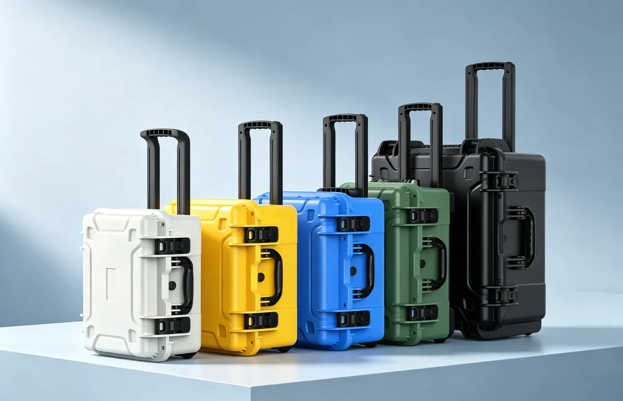
Thermoformed EVA gives tighter three-dimensional cavities suited to complex outlines, while carved EVA is often more flexible and faster for small-batch, high-variety delivery; the choice depends on quantity, shape complexity and budget.
Latches, Hinges, Pressure Equalization Valves and Stacking Loads
Case hardware is often treated as an accessory, yet it is the last mile of protective performance. Latches decide whether the gasket compresses evenly, hinges decide lid cycling life, and the pressure equalization valve decides whether pressure differentials release gently.
Latch selection turns on clamping force and count. Higher sealing grades need greater compression and more latches; too many slows opening, too few leaves the gasket unevenly compressed. As a rule, at least two main latches per side, increasing to three where a long edge exceeds 600 mm. Hinges must carry the lid's own weight through repeated cycles, so heavy cases should use metal hinges with an opening limit that protects the gasket face at full open.
The pressure equalization valve is a key item for sea and air freight. Inside is a micro-porous breathable membrane that lets air pass slowly to balance pressure while blocking liquid water and dust. Without it the case develops positive or negative pressure under temperature swings — negative pressure draws external moisture in through seal weak points, and positive pressure pushes the gasket open. It is normally mounted high on the case wall, away from where water might pool.
Stacking load must distinguish empty from loaded conditions: empty stacking tests the shell's own stiffness, while loaded stacking adds contents weight plus transport acceleration. The design should state a maximum stacking tier and provide corner locating features to stop upper cases from shifting or sliding off.
| Hardware | Function | Failure consequence | Selection / inspection point |
|---|---|---|---|
| --- | --- | --- | --- |
| Latch | Compress gasket | Water and dust ingress | Count and force matched to case length |
| Hinge | Support lid cycling | Lid sag, gasket face damage | Metal parts + opening limit |
| Pressure equalization valve | Balance pressure differential | Moisture ingress, gasket pushed open | Micro-porous membrane, mounted high |
Temperature, Humidity, Salt Spray and Transport Testing
Protection design cannot stop at drawings; it must turn "can it survive" into a checkable result through testing, and since hobbing components are exported in high proportion, testing covers climatic environment, mechanical environment and transport-chain simulation.
Salt spray testing follows the neutral salt spray (NSS) method of GB/T 10125: a 5% sodium chloride solution sprayed at a chamber temperature of 35 °C, pH held between 6.5 and 7.2, with a collection rate of 1–2 mL per 80 cm² per hour. Duration is graded by service condition — inland transport may use 48–96 h, coastal or sea-freight items commonly 240 h, severe high-salt environments up to 480 h or 720 h. The assessment covers whether case hardware, latches, hinges and metal-contacting liner areas show functionally significant corrosion. Duration represents resistance under those test conditions only, not actual sea-freight years.
The other climatic test is temperature-humidity cycling between -40 °C and +70 °C with 85% relative humidity segments, observing shell dimensional stability, gasket hardness change and liner embrittlement. Foam stiffens at low temperature and its cushioning curve shifts, which matters for sea routes crossing high latitudes.
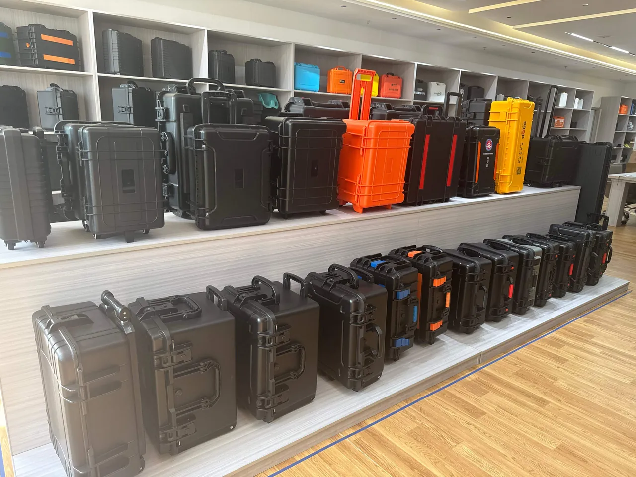
On the mechanical side, the GB/T 4857 series covers basic transport package drop, stacking, vibration and impact items, ISTA 3A/3E simulates real distribution chains, and ASTM D4169 uses different distribution cycles to tailor test severity. These are not substitutes but validation tools along different dimensions. The full GB/T 4857 project structure is covered in GB/T 4857 Transport Packaging Testing for Protective Cases.
| Test family | Reference standard | Main purpose | Meaning for hobbing machine parts |
|---|---|---|---|
| --- | --- | --- | --- |
| Salt spray | GB/T 10125 | Verify corrosion resistance | Protects hardware and mating surfaces |
| Temperature-humidity cycling | Relevant environmental standards | Verify stability | Prevents condensation and liner embrittlement |
| Drop / impact | GB/T 4857, ISTA | Verify impact resistance | Protects tapers and electrics |
| Vibration | GB/T 4857, ASTM D4169 | Verify micro-vibration resistance | Prevents fretting and resonance |
Customization, OEM/ODM and Acceptance Criteria
Packaging for hobbing components is almost never off-the-shelf: hob spindle interfaces, worktable dimensions and electrical layouts differ between builders, so customization is the norm. The JUNZHIJIA path is not simply "measure and tool up"; it starts from component accuracy constraints, derives the structure, then returns to a manufacturable, reusable solution. The path reduces to six ordered actions:
- Accuracy survey: identify each component's datum faces, tolerances and sensitive directions, flagging all no-contact surfaces.
- Chain identification: confirm transport mode, handling count, stacking tiers and destination climate, setting protection grade targets.
- Structural zoning: divide cavities by rigid-soft zoning and set the fixing method for each.
- Liner modeling: design EVA cavities from the 3D outline, marking support points and removal paths.
- Prototype verification: build a first-article case and run drop, vibration and sealing tests for displacement or damage.
- Production freeze: lock the liner drawing and hardware configuration into process documents.
The value of this path is converting experience-based judgment into verifiable engineering actions: any displacement found during prototyping feeds back into support-point positions and liner density instead of waiting for rework after parts arrive. For batch or repeat-order customers, JUNZHIJIA supports OEM/ODM — appearance and marking can be customized to the customer brand, or a dedicated structure can be co-developed with shared process documents; existing case owners can also use liner retooling services to extend case life and reduce batch cost.
Acceptance criteria close out the customization and should be written as measurable items, avoiding subjective wording such as "looks fine."
| Acceptance item | Method | Pass criteria |
|---|---|---|
| --- | --- | --- |
| Outline and compartments | Visual + drawing comparison | Cavity position deviation ≤2 mm |
| Liner fit | Trial loading | No looseness, no compression marks |
| Sealing performance | Spray / immersion test | Meets agreed IP rating |
| Hardware function | Open-close and lock test | Even latch compression, smooth hinges |
| Stacking load | Loaded stacking | No deformation, no shifting |
| Rust prevention | VCI compatibility and salt spray sampling | No functional corrosion within agreed duration |
The liner drawing supports future restocking and retooling, the packing list allows physical counting, and desiccant and humidity indicator records show whether the internal environment met target; for export items, compliance labels and accompanying documents must be prepared to destination requirements.
Frequently Asked Questions FAQ
Q: Can a hob spindle simply be laid flat in the case for transport?
A: Laying it flat is not advisable. Hob spindle taper contact is usually specified at 85% or better and radial runout is held in the 3 μm range, so laying the whole shaft flat makes the taper and bearing seats carry bending load from self-weight, and long-distance vibration can add fretting wear at the seats. The sound approach rests the shaft on two V-shaped EVA cradles positioned on the rigid sections near the bearing seats, leaving the taper and seats suspended. The taper end receives a cap lined with PE soft film, while the other end takes an elastic axial block limiting end-play with 1–2 mm retained. The recommended fixing logic is two-point radial location plus one elastic axial constraint, so the shaft can only shift elastically by a small amount rather than slide across its supports. If the hob and arbor ship separately, the hob should stand upright or be held by tooth-groove blocks so no cutting edge touches a hard surface.
Q: Should an indexing worm pair ship assembled or separated?
A: It depends on distance and vibration severity, but separated shipment is generally safer. When separated, the worm and worm wheel are each wrapped in VCI film, sleeved in PE bags and placed in separate compartments, so the mating surfaces never contact hard media and backlash is unaffected. If shipped assembled, the mesh clearance must first be locked with locating blocks to stop the flanks repeatedly bumping and shifting the contact pattern; both bearing seats of the worm should be axially fixed with added axial stops, and the bearing cavity filled with grease and plugged so that after jolting the grease does not pile to one side and cause local dry friction on the flanks. Short internal factory shuttles can travel assembled, while cross-border sea freight is better separated, with desiccant and a humidity indicator card monitoring the internal environment throughout the voyage and a record kept for receiving inspection. Where the pair is large, shipping the worm and wheel in separate cases entirely is common practice.
Q: Why does an encoder need its own compartment instead of riding with the motor?
A: An encoder is one of the most impact-sensitive parts on the machine, with only tens of microns between the disc and the read head, so a single knock can leave the disc eccentric or cracked, and such damage is usually discovered only after power-up at the destination. Separating the encoder from the motor body allows different cushioning for each: the motor is heavy and uses a medium-density EVA cavity with a PE foam base that spreads impact energy through the whole cavity, while the lighter, more sensitive encoder uses softer resilient material with movement limited by its own shaped pocket. Electrical parts also need static protection, so they should go into ESD bags or ESD foam compartments, with connectors sealed by protective caps and cables coiled no tighter than their minimum bend radius. Desiccant is placed inside the case to hold humidity down through the journey, and the encoder should be the last item loaded so it is not disturbed by packing of heavier parts.
Q: What exactly is the difference between IP65 and IP67 for a hobbing machine component case?
A: The difference lies in how water contacts the case rather than a simple larger number. IP65 protects against water jets, tested with a 6.3 mm nozzle at roughly 12.5 L/min sprayed from all directions; IP67 protects against short immersion, tested by submerging the case in 1 m of water for 30 minutes. Both share the same dust rating, fully dust tight, so the distinction is entirely about liquid challenge severity. The practical meaning for hobbing machine components is that IP65 usually suffices for factory shuttles and dry storage; brief outdoor handling exposed to heavy rain or washdown favors IP66; and sea-freight decks or flooded dock conditions call for IP67 paired with a pressure equalization valve. Remember that IP is a whole-case system property depending on gasket compression, latch force and cable gland sealing, so any weak link lowers the real rating below the label. For that reason, a case should be re-tested after any change of gasket supplier or latch model.
Q: Why does condensation form inside a case during sea freight, and how is it prevented?
A: Condensation comes from the breathing effect driven by temperature swings. The case absorbs heat by day and cools at night, internal air contracts into negative pressure, and if a seal weak point exists external moisture is drawn in; when the case cools below the dew point again, that vapour condenses on cold metal surfaces. Prevention has three parts: first, choose an IP65 or higher case whose gasket compresses evenly, with latch count and force matched to case length; second, fit a pressure equalization valve so pressure differentials equalize slowly through a micro-porous breathable membrane that blocks liquid water and dust while still allowing air exchange; third, place desiccant sized to case volume and voyage, monitored by a humidity indicator card that lets the receiver judge whether the internal environment stayed within target. For long sea voyages all three should be used together rather than relying on extra desiccant alone. On long routes the daily swing inside a steel container can reach 20 °C, so a case that stays sealed and dry in the factory may still breathe in transit. Log the indicator card reading at both ends and compare.
Q: For hobbing machine parts, should the liner be EVA or EPE?
A: In most cases EVA is primary and EPE secondary. EVA is a closed-cell material with good resilience and durability, well suited to carved cavities that hold parts in position over time; EPE cushions well but has limited resilience and gradually compacts under prolonged vibration, so location accuracy drifts, making it better for underlays or void filling. The typical hobbing machine combination is an EVA shaped cavity plus a PE load-bearing base plus an IXPE face liner: EVA provides location and scratch protection, PE foam carries weight into the case skeleton, and IXPE bonded to contact faces gives fine anti-scratch and uniform cushioning. Complex or multi-point-supported parts can use thermoformed EVA, while small-batch high-variety delivery is often faster and more flexible with carved EVA, where a change of part outline costs only a new cutting file rather than a new mould. Whichever route is taken, the liner drawing should be archived with the case so replacement inserts match the original cavities.
Q: How should guideway scraped surfaces and tool head mounting faces be protected?
A: The core principle is no foreign contact and no load on the scraped surface. A guideway scraped surface is a hand-scraped pattern of micro-hollows and micro-peaks with modest hardness, and a single fallen bolt is enough to press a dent that needs re-scraping, so it should first be covered with anti-scratch film, then separated from any movable accessory by timber or PE supports, and finally secured with limit blocks so the guideway cannot slide longitudinally inside the case. Tool head mounting faces are equally sensitive: clean, apply rust-preventive oil, apply PE protective film, then use EVA flat pads to carry the clamping force, ensuring that force lands on the non-machined area around the face rather than on the machined surface itself. The arbor mounting bore should receive a bore-edge protection ring to guard its edge from knocks during loading and unloading, and the same ring prevents the bore edge from scoring the arbor when the head is lifted.
Q: What steps are involved in customizing a hobbing machine component protective case?
A: The work reduces to six ordered actions. First, an accuracy survey identifies each component's datum faces, tolerances and sensitive directions, flagging all no-contact surfaces. Second, chain identification confirms transport mode, handling count, stacking tiers and destination climate, setting protection grade targets. Third, structural zoning divides cavities under a rigid-soft rule and sets each cavity's fixing method. Fourth, liner modeling designs EVA cavities from the 3D outline, marking support points and removal paths. Fifth, prototype verification builds a first-article case and runs drop, vibration and sealing tests to check for displacement or damage. Sixth, production freeze locks the liner drawing and hardware configuration into process documents. For batch or repeat-order customers, JUNZHIJIA supports OEM/ODM together with liner retooling services.
Conclusion and Related Reading
Protecting hobbing parts centers on accuracy datum surfaces: isolate tapers and scraped faces, lock location rigidly, cushion with soft liners, and seal against moisture. Prepared by Kexin New Materials (Guangdong) Co., Ltd. with JUNZHIJIA OEM/ODM support.
Related Reading