


A press brake ram is not merely heavy — it is the dimensional reference of the entire machine. The short answer: support the ram at three or more evenly spaced points so no section is left spanning unsupported, store punches and dies with the cutting edge facing inward or upward on a liner softer than the edge itself, and select a case that has been validated against transport vibration and drop conditions. The tool-mounting face of a ram is typically held to a flatness tolerance of about 0.02 mm per metre. Once that face takes a permanent set in transit, no amount of crowning or deflection compensation will bring the machine back to consistent bend angles.
Press brakes usually ship as disassembled sub-assemblies — ram, upper and lower tooling, back gauge, hydraulic manifold — and are re-assembled at the customer site. That disassembled leg of the journey is where accuracy is most often lost. A micro-chipped punch edge shows up after commissioning as a visible witness mark on the bent part, and a slightly twisted ram shows up as a difference in angle between the two ends of the same sheet. This article works outward from failure modes to fixturing method, liner architecture, case rating, test references and incoming inspection so that machine builders, used-machine traders and export agents can specify a case directly from the text.
Contents
- Three failure modes in press brake component transport
- Fixturing the ram against bending
- Punch, die and clamp edge protection
- Precision fixturing for the back gauge and servo drive
- Packaging the hydraulic manifold and crowning unit
- Liner architecture and hardness gradient
- Case rating and sealing selection
- Environmental and transport test references
- Sizing by mass and load verification
- Export stacking and outer packaging
- Outgoing inspection and acceptance sampling
- OEM/ODM customisation and prototyping
- Frequently Asked Questions
- Conclusion and further reading
Three failure modes in press brake component transport
The first mode is bending. Rams and tooling bars are extreme length-to-thickness members. A three-metre ram supported only near its ends will sag in the middle under its own weight, and sustained stacking load gradually converts that sag into a permanent set. Nothing is visible when the crate is opened; the deviation only appears once the machine is assembled and a test part is bent, which makes responsibility very hard to trace.
The second mode is edge damage. The tip of a punch is usually hardened to somewhere between HRC 45 and HRC 52 — a classic high-hardness, low-toughness combination. Any point contact, any steel-on-steel impact, or any situation where the edge itself carries the load will chip it. Once a chip exceeds roughly 0.05 mm in depth, it leaves a visible impression on the outer surface of every bent part.
The third mode is contamination and displacement of precision elements. If chips or dust reach a linear scale, a back gauge rail or a servo encoder, both homing accuracy and repeatability degrade. A hydraulic spool that shifts axially under vibration also scores the valve lands.
| Failure mode | Typical components | Immediate cause | Primary countermeasure |
|---|---|---|---|
| --- | --- | --- | --- |
| Bending | Ram body, long die bars | One- or two-point support, stacking load | Three or more evenly spaced supports plus mid-span cradles |
| Edge chipping | Punch tip, die shoulder | Steel-on-steel impact, edge bearing load | Edge sleeves, soft bearing surfaces, edge facing inward |
| Accuracy drift | Linear scales, guide rails, servos | Dust, vibration, axial creep | Dedicated sealed cavity, damping pad, axial stop blocks |
| Oil contamination | Hydraulic manifold, cylinders | Open ports, pooled oil | Port plugs, absorbent layer, drainage channel |
These modes rarely occur in isolation. Random vibration over many hours loosens fasteners, loosening restores freedom of movement, and that freedom converts reciprocating displacement into localised wear. Liner design must therefore address both initial restraint and the retention of that restraint over time. The practical test is simple: after the case has been tilted, upended and shaken, no component inside may retain any free play.
Fixturing the ram against bending
The ram is long, of moderate wall thickness, and machined on more than one face. The goal is to keep it in a zero-bending-moment condition for the entire journey. In practice this means placing the ram horizontally on a cradle beam of comparable length, then supporting that beam on blocks spaced no more than 600 mm apart. As a rule of thumb a 3000 mm ram needs at least five support points, while anything under 2000 mm can usually be handled with three or four.
The tool-mounting face must face upward or sideways and must never be loaded. If the face carries T-slots or clamp slots, fill them with hardwood or engineering-plastic strips cut to fit, so that the slot edges cannot be chipped by loose hardware during vibration. Plug and wrap all hydraulic ports before the ram goes anywhere near the liner, otherwise residual fluid will migrate into the foam.
Axial restraint comes from stop blocks. Leave 2 to 3 mm of compression between the block and the ram end face, filled with self-adhesive closed-cell foam — enough to prevent creeping without introducing a rigid impact path. Side restraint comes from a liner cavity matched to ram height, with 1 to 2 mm total clearance.
Field observation: in more than half of the ram distortion complaints we review, the root cause is that the crate supported the ram only at its two ends. The case was stiff enough; the support scheme was not.
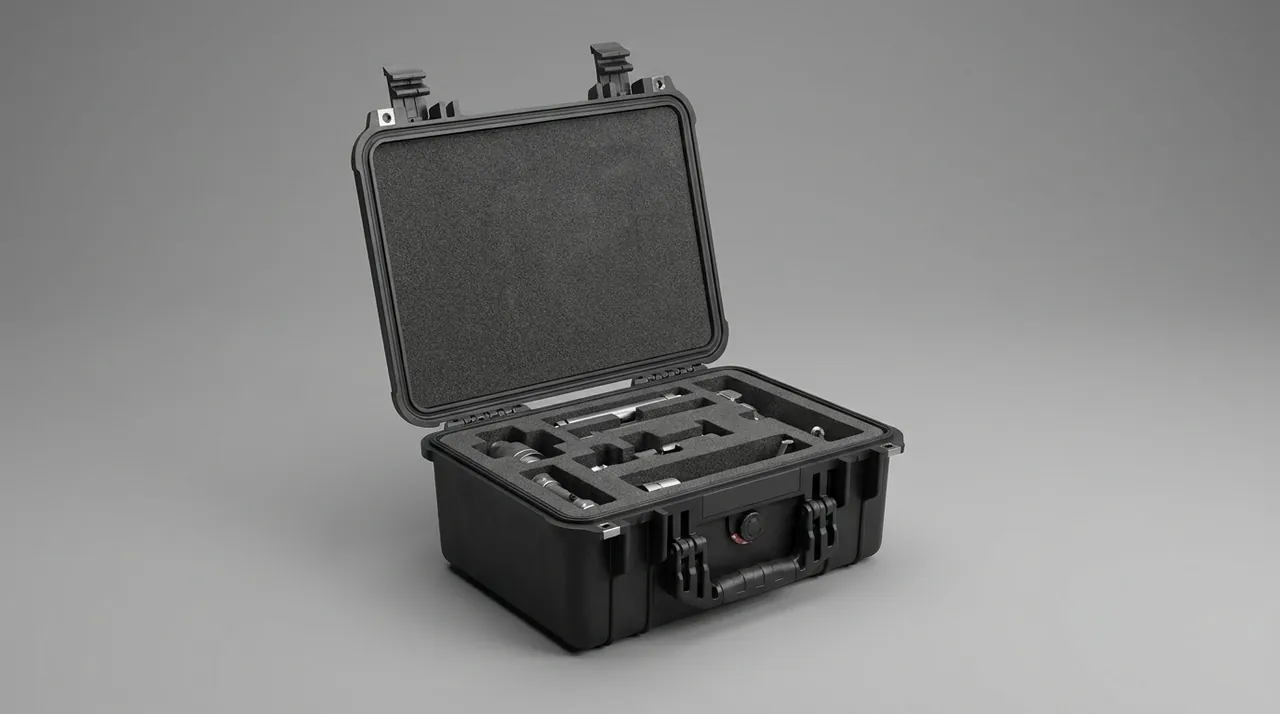
When the ram ships with its crowning mechanism attached, fit a temporary locking plate across the mechanism first. The wedges inside a crowning unit will migrate under vibration, and a crowning curve that has shifted is difficult to detect until a test part is run. The same logic that governs the locking of CNC spindle assemblies for transport applies here: what matters is limiting residual displacement of a precision sub-assembly, not merely holding it in place.
Punch, die and clamp edge protection
Tooling is the most frequently changed and most easily damaged part of a press brake. The punch tip and the die shoulder are stress concentrators, and the governing rule is that the edge must never come into contact with a material harder than itself.
The recommended sequence is: sleeve the edge, seat it in the cavity, then restrain the whole assembly. Edge sleeves in polyurethane or nitrile rubber work well in the Shore A70 to A85 range. Below A70 the edge cuts into the sleeve and the sleeve stops supporting anything; above A85 there is not enough compression travel and impact passes straight through to the edge.
A lower die is normally a square section or a V-grooved bar, heavy and with a flat base. It should sit with the V opening facing the case side or facing up, on a 5 to 10 mm closed-cell foam pad. If several die bars share one case, each layer needs a rigid separator board so that the bars never bear on each other.
Clamp blocks, punch holders and wedges are the components most often dropped loose into a crate, and they are the most common cause of accidental edge damage. Give each small part its own machined pocket, one part per pocket, with a finger relief at the base.
- One pocket per part, no shared cavities for loose hardware
- Pocket depth at least one third of part height
- Finger relief at least 30 mm wide
- Minimum wall between adjacent pockets 15 mm
For slot depth and draft-angle values that also work for tooling bars, see custom foam insert cavity and relief design.
Precision fixturing for the back gauge and servo drive
The back gauge assembly contains linear rails, ball screws, servo motors and stop fingers. These share three sensitivities: tight running clearance, contamination, and axial shock.
A linear rail must travel either preloaded or positively located. Fit a temporary locating pin at each end, or keep the carriage preloaded with a shipping bracket. If the carriage is left free, the balls circulate back and forth under vibration with no preload, and Brinelling appears on the raceway — felt later as a stepped, notchy motion.
Ball screws should be fixed horizontally or vertically and must not be loaded at mid-span. Because their length-to-diameter ratio is high, any mid-span flexing changes nut preload. Where screw and motor ship assembled, fit a transport lock between the two and mark it clearly for removal before commissioning.
Servo motors and encoders are better off in their own closed cavity. A desiccant sachet in that cavity controls relative humidity. Do not coil cables at a small radius; keep the bend radius at six times the cable outer diameter or greater, and cap every connector.
Packaging the hydraulic manifold and crowning unit
The problem with a hydraulic manifold is not strength but cleanliness and residual oil. A manifold removed after machine testing still contains fluid, and movement during transport will push it out of any open port. Three actions before dispatch: drain, plug, absorb.
Drain means recovering as much fluid as possible. Plug means closing every port with a threaded plug or purpose-made plastic cap fitted with an O-ring. Absorb means laying an oil-absorbent mat under the block and forming a shallow drainage channel in the case floor, so that the small amount that does escape cannot spread across the liner.
A crowning unit contains wedges, rollers and adjustment screws. These migrate under vibration, and the compensation curve ends up offset by the time the machine is re-assembled. Lock the adjustment screws with nylon ties or a temporary clamp plate, and insert thin shims between wedge contact faces to raise friction.
Solenoid coils, pressure switches and proportional-valve amplifiers belong in a separate compartmentalised box travelling with the main case. If they must share the case, they go in their own recess and must never rest on the valve body.
| Component | Packaging action | Verification point |
|---|---|---|
| --- | --- | --- |
| Hydraulic manifold | Drain, plug ports, absorbent base layer | All port plugs present, no visible weep |
| Crowning unit | Lock adjustment screws, shim wedges | Locking device carries a removal tag |
| Proportional amplifier | Individual ESD bag, own pocket | ESD marking, no crush marks |
| Cylinders and hoses | Port caps, hose-end sleeves | No deformed ports, no exposed threads |
Static-control practice for card-level electronics is covered in ESD shielding cases for precision components; amplifier boards are particularly sensitive in low-humidity conditions.
Liner architecture and hardness gradient
A press brake case liner is not a single slab of foam. It is a stack of materials, each doing one job. From the shell inward: damping layer, load-spreading layer, locating layer, contact layer.
- Damping: open- or semi-closed-cell foam, 20 to 30 mm, absorbs drop and random-vibration energy
- Load spreading: PE or EVA sheet, 15 to 25 mm, converts point loads into distributed pressure
- Locating: machined EVA or PU, milled to the component profile
- Contact: flocked fabric or a soft PU film that will not mar a machined face
The hardness gradient runs soft, hard, soft. An outer layer that is too hard transmits impact straight through; an inner layer that is too hard scratches mating surfaces. A combination that works well in practice is Shore A25–A35 outside, A40–A55 in the middle, A20–A30 at the contact face.
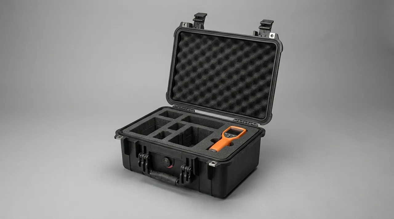
Moulding tolerances and drawing conventions for EVA are described in EVA foam insert forming process and drawing requirements. For a ram weighing more than 80 kg, switch the locating layer to high-density PE and add steel reinforcement under the pocket floor; otherwise the cavity base will deform after repeated loading cycles.
Case rating and sealing selection
The right case depends on how the goods travel and what they are exposed to. For export shipments by sea container, specify a rotationally moulded or injection moulded case with a gasket. For short domestic transfers between plants, a heavy-duty corrugated outer with a good liner usually controls cost better.
Sealing performance is judged to GB/T 4208 or IEC 60529. For sea freight and outdoor transfer IP67 is the sensible target; IP54 is sufficient for closed domestic vehicles. Three questions decide the requirement: will the case see rain, is there dust in the environment, and does it contain a hydraulic component that was not fully drained?
The gasket is where sealing is won or lost. Insufficient compression leaks; excessive compression makes the case hard to close and accelerates ageing. Closed-cell silicone gaskets compress best at roughly 25 to 35 percent. Material selection across temperature ranges is discussed in protective case gasket material selection.
Fit a pressure equalisation valve for air freight and for repeated temperature cycling. The valve must be both waterproof and breathable, and it should not face the precision components inside, so that condensation cannot drip onto them.
Environmental and transport test references
Verification normally draws on three families of standards: transport packaging tests, environmental tests, and enclosure ratings.
For packaging, the GB/T 4857 series defines drop, stacking and vibration tests; the ISTA series provides distribution-chain sequences; ASTM D4169 combines test intensities into a distribution cycle. Export projects are often asked for ASTM D4169 and ISTA 3A together.
For environmental performance, MIL-STD-810H supplies methods and procedures for high temperature, low temperature, humidity, vibration, shock and salt fog. One clarification matters commercially: MIL-STD-810H is used in this industry purely as a source of environmental test methods. It is not a military certification and does not confer military product qualification of any kind. If a purchaser cites the standard in a technical agreement, the agreement should name the specific method and procedure.
| Standard | Scope | Typical citation |
|---|---|---|
| --- | --- | --- |
| GB/T 4857 | Basic tests for transport packages | Drop height, stacking load, random vibration spectrum |
| ISTA 3A / 3E | Parcel and unitised load | Combined distribution chain sequence |
| ASTM D4169 | Distribution cycle simulation | Assurance level and DC selection |
| MIL-STD-810H | Environmental test methods (not a military certification) | Method 514 vibration, Method 516 shock |
| GB/T 4208 / IEC 60529 | Enclosure ingress protection | IP54/IP67 classification |
| GB/T 9061 | General specification for metal cutting machine tools | Accuracy and assembly reference |
Test sequence and pass criteria are described in ISTA transport test procedure. Where a report is required, agree the test level, sample quantity and acceptance criteria in the contract before testing starts, so that a completed test can actually be judged pass or fail.
Sizing by mass and load verification
Press brake case sizes span an enormous range. An 835 mm segmented punch may weigh under 5 kg, while a 4000 mm through-hardened punch can exceed 120 kg, and a ram might be anywhere from 300 kg to 1500 kg. Selecting by mass band is far more reliable than selecting by dimensions.
| Component mass | Suggested case type | Handling method | Liner notes |
|---|---|---|---|
| --- | --- | --- | --- |
| Up to 20 kg | Carry case, moulded | One or two hands | EVA pocket, wall ≥ 15 mm |
| 20–60 kg | Mid-size case with side handles | Two-person lift | Reinforced base, load-spreading plate |
| 60–200 kg | Caster case or pallet case | Casters or forklift | High-density PE pocket, steel base reinforcement |
| 200–800 kg | Heavy pallet case | Forklift | Timber or steel sub-frame, multi-point support |
| Over 800 kg | Steel base with cover | Crane or forklift | Rigid base frame, anti-tip design |
Load verification must cover both static stacking and dynamic impact. Static stacking is calculated from the total mass above the lowest case, with a safety factor of at least 3. Dynamic impact is derived from the velocity equivalent to the specified drop height, and the design limit is usually taken as two to three times the static case. If the case will sit outdoors for extended periods, add UV ageing and rainwater accumulation to the assessment.
Support count directly drives floor loading. With a 1200 kg ram on five supports, static load per point is roughly 2.4 kN, rising above 6 kN once the dynamic factor is applied; the floor panel needs local thickening or steel pads at each support position.
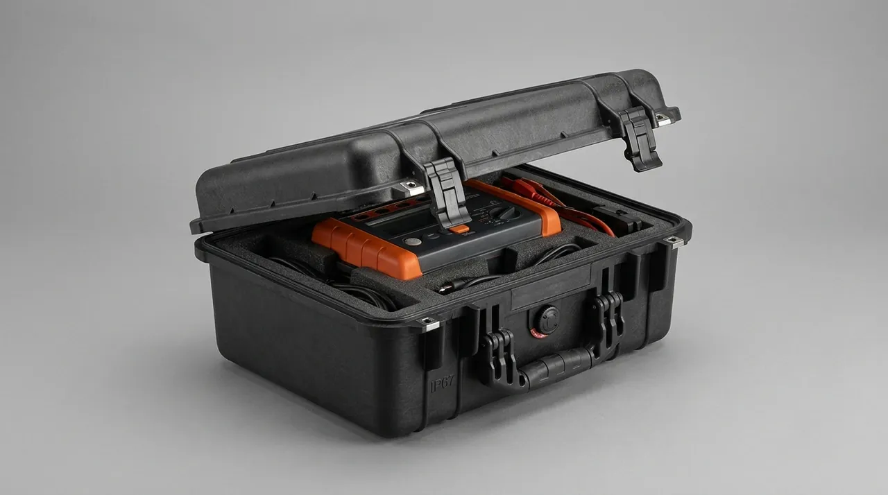
Centre of gravity is the other variable that gets overlooked. A ram packed together with extended tooling bars will have its actual centre of gravity biased toward the tooling side, and lifting points placed at the geometric centre will tilt the case the moment it leaves the ground. Measure the centre of gravity during the trial fit, reposition the lifting points and forklift pockets accordingly, and mark the CG projection line on the case. For cases with a length-to-width ratio above 3, add anti-tip feet as well.
Export stacking and outer packaging
On export routes the inner protective case rarely carries the full duty cycle alone. A typical build-up is a sealed inner case, a cushioning intermediate layer, and a plywood crate or steel-strapped pallet outside.
Timber outer packaging must satisfy phytosanitary requirements: heat-treated or fumigated wood with the correct mark. Where the destination imposes further restrictions, plywood, oriented strand board or a steel frame are alternatives that are generally not subject to plant health controls.
Stacking design needs an explicit orientation mark and a stated maximum stack height. A ram is a low-CG, slender component, and the case has a large length-to-width ratio; cross-stacking one case on top of another creates mid-span bending. Stack identical cases in the same orientation, with a full-sheet separator between layers to spread the load.
Lifting and handling marks should cover centre of gravity, lifting points, no-roll and no-invert instructions. Any case containing a linear scale or an encoder should also carry a tilt indicator so that an over-limit event can be identified immediately on arrival.
Outgoing inspection and acceptance sampling
Outgoing inspection is best built around four checks: appearance, fit, restraint, marking.
- Appearance: no cracks or distortion, gasket fully seated, hinges and latches operating freely
- Fit: component clearances match the drawing, no forced insertion and no obvious looseness
- Restraint: stop blocks, locking plates and ties all fitted, removal tags legible
- Marking: model, quantity, mass, CG, orientation, case number and packing list all consistent
Incoming inspection by the purchaser is normally handled by sampling. For batch deliveries, a single sampling plan to GB/T 2828.1 at general inspection level II works well, with AQL values separated by defect class: 0 for critical, 0.65 for major, 2.5 for minor. The mechanics of writing such a plan are covered in custom case acceptance and AQL sampling.
Returnable cases also need a usage log. EVA pockets lose their fit gradually, and the liner typically needs replacement after 30 to 50 round trips.
OEM/ODM customisation and prototyping
A custom press brake case project normally runs through six stages: requirements, drawing review, liner modelling, prototype, fit-up validation, production.
The requirements stage needs a component list, individual masses and envelope dimensions, transport mode, stack height and any export requirement. Drawing review focuses on which faces are machined and which must not be loaded. Liner modelling usually starts with a 3D scan of the component, from which the cavity is milled, holding the fit clearance to 1 to 2 mm.
The prototype must be validated with the real component: load it into the case, apply the intended stack load, leave it to settle, then check for displacement and witness marks. Only after that does the design go to production.
Kexin New Materials (Guangdong) Co., Ltd., which manufactures the JUNZHIJIA range, builds to drawing for ram cases, long tooling cases and back gauge assembly cases, combining case structure, liner cavities, sealing class and hardware in one configuration, and supplies wholesale, distribution and worldwide fulfilment with material and inspection documents available by contract. OEM and ODM projects can be branded to the customer's identity. For long, load-bearing tooling geometries there is useful common ground with forging die transport cases.
Frequently Asked Questions
Q: Why can a press brake ram case not simply rest on two supports?
A: Because with two supports the middle of the ram is left spanning, and self-weight plus stacking load produce the maximum bending moment exactly at mid-span. Given enough time in that state, the deflection becomes permanent. A ram's tool-mounting face is normally held to about 0.02 mm per metre flatness, and once it exceeds that no crowning correction can recover the machine. Support the ram on blocks spaced no more than 600 mm apart — at least five points for a 3000 mm ram, and three or four below 2000 mm — and set every support to the same height. Unequal supports are as damaging as too few, because the tallest block carries most of the load while the remainder act as decoration. A quick check before the case is closed is to slide a 0.05 mm feeler gauge under each cradle; if it enters, that support is not in contact and needs shimming. Where the ram is longer than 4 m, increase the count rather than the block size, since a stiffer block does not reduce mid-span moment.
Q: Can punches and dies travel in the same case?
A: Yes, but they must be physically separated, and the separation has to be structural rather than cosmetic. The punch tip and the die shoulder are both hard, low-toughness stress concentrators, and direct contact or one edge bearing on the other will chip them. Place them in separate layers with a rigid separator board between, give every item its own machined pocket, and sleeve the edges. Sleeve hardness in the Shore A70 to A85 band works well: below A70 the edge cuts into the sleeve and support is lost, above A85 there is too little compression travel and impact reaches the edge unchanged. If space is tight, the absolute minimum is that no edge ever touches a material harder than itself, with at least 20 mm of soft material between adjacent edges. Remember too that a die is usually several times heavier than a punch of the same length, so plan the layers by mass: dies at the bottom on the load-spreading layer, punches above them in their own tray.
Q: What ingress protection rating does a press brake case need?
A: Match it to the route rather than defaulting to the highest available figure, because every step up in sealing class adds cost, weight and latch effort. Sea freight with rain and dust exposure justifies IP67 to GB/T 4208 or IEC 60529. Closed domestic trucking with no un-drained hydraulic parts is usually served by IP54. Three questions decide the answer: will the case see rain, is there abrasive dust in the environment, and does it contain a component that still holds fluid? If the case contains a manifold that has not been drained, raising the IP rating achieves very little, because the dominant risk is oil escaping from the inside rather than water entering from outside. Plug the ports and add an absorbent layer under the block instead. Gasket compression should sit between 25 and 35 percent: below that the seal weeps, above it the case becomes hard to close and the gasket ages faster than its rated life.
Q: Can a hydraulic manifold share a case with mechanical parts?
A: It is not advisable to put them in the same cavity, for a reason that has nothing to do with strength. A manifold removed after machine testing still contains hydraulic fluid, and once it spreads, oil contaminates machined faces, the liner and any electrical component nearby. Keep the manifold in its own closed compartment, plug every port with a plug that carries an O-ring rather than a plain cap, lay an absorbent mat underneath, and form a shallow drainage channel in the compartment floor so that the small quantity which does escape stays local. If a shared case is unavoidable, build a full-height divider around the manifold area with its own base channel, and make sure no through-opening links that compartment to the mechanical side. Foam is not a barrier to oil: a closed-cell liner will still wick fluid along bolt holes unless the divider itself is solid. Label the compartment clearly as well, so that the receiving technician knows a fluid-bearing component is inside before the case is opened.
Q: What actually threatens linear scales and servo motors in transit?
A: Dust ingress, axial shock and cable damage, in that order of frequency. The gap between a scale reading head and the scale body is very small, so even a few metal chips or a film of abrasive dust cause signal jumps and eventually permanent scratching of the grating. Axial impact on an encoder shifts its zero reference, which appears later as a homing error that cannot be corrected from the parameters. Put these parts in a dedicated sealed cavity with a desiccant sachet, add axial stop blocks to limit creeping, keep cable bend radius at six times the outer diameter or more, and cap every connector. Cable damage is often caused simply by a heavy adjacent component sliding onto a cable during handling, so route cables behind a rigid divider rather than across an open cavity, and never let a tooling bar share the same cavity as a scale or a motor.
Q: Should the liner be EVA or PU?
A: It depends on component mass and how often the case is opened, and most projects end up using both. EVA is cheaper, machines cleanly and holds a cavity well, which suits small to medium components and low-frequency handling. PU moulds with better resilience and tear resistance and shrugs off the abrasion of repeated loading, which suits heavy parts and frequent turnover. A typical build-up uses high-density PE for the load-spreading layer, EVA for the locating layer, and a soft PU film at the contact face. Above roughly 80 kg per component, switch the locating layer itself to high-density PE and add steel reinforcement beneath the pocket floor, because a soft pocket base creeps over repeated handling cycles even when it feels perfectly rigid on the first fit. Check the contact layer separately as well: it wears through long before the structural layers show any change. If in doubt, prototype both options and compare them after twenty load-and-unload cycles, which is a cheap test relative to re-machining a cavity later. Whichever combination is chosen, specify it by hardness and density rather than by trade name, so that a replacement batch behaves like the original.
Q: Does citing MIL-STD-810H mean the case is military certified?
A: No, and the distinction matters in contracts. In this industry MIL-STD-810H is cited only as a source of environmental test methods; it defines procedures and parameters for high temperature, low temperature, humidity, vibration, shock and salt fog. It is not a military certification and it does not confer military product qualification of any kind, so a case described this way is not a military-qualified product. Method 514 for vibration and Method 516 for shock are the parts most often referenced, but a citation only becomes meaningful when it names the procedure number, the intensity level and the duration. Without those details a completed test cannot be judged pass or fail and the report carries little contractual value. Where a customer genuinely requires formal qualification, that is a separate programme with its own documentation, and no packaging test report can imply it. Describe a product in your own documents as tested to the cited methods and procedures, never as certified or qualified to the standard.
Q: What steps does a custom press brake case project go through?
A: Six stages: requirements, drawing review, liner modelling, prototype, fit-up validation, production. The first two need a component list, individual masses and envelope dimensions, transport mode, stack height and export requirements, together with a clear statement of which faces must not be loaded. Liner modelling normally begins with a 3D scan, and the cavity is milled from that point cloud to a fit clearance of 1 to 2 mm, which is tight enough to restrain the part without making it difficult to lift out by hand. The prototype must then be loaded with the real component and left to settle under the intended stack load. Only when there is no displacement and no witness mark should the design be released for volume production. Skipping the fit-up step is the single most common reason a project needs a second round of tooling. Budget the drawing review properly as well, because a change made on paper costs a small fraction of the same change made in tooling.
Q: How often does a returnable case liner need replacing?
A: It depends on handling frequency and load rather than on elapsed time. EVA pockets progressively lose their fit, and typical practice is to assess replacement after 30 to 50 round trips. High-density PE pockets carrying heavy components last considerably longer, but if the base bearing surface collapses or cracks they should be replaced immediately regardless of cycle count, because a cracked base stops distributing load and starts concentrating it. Keep a usage log and inspect at fixed intervals, looking for three things: pocket walls that have splayed outward, a collapsed pocket floor, and a contact layer worn through. Any one of those conditions is sufficient reason to schedule replacement. As a general rule, replace the liner well before the component itself shows any mark, since restoring a liner costs a small fraction of re-machining a ram face. Write the interval into the maintenance schedule rather than relying on operator judgement, and keep one spare liner set for each case that travels frequently.
Conclusion and further reading
The value of a press brake component case lies not in the case itself but in whether it delivers the ram's flatness, the tooling's edge integrity and the back gauge's positioning accuracy intact. Three points prevent most transit losses: support the ram at multiple even points with nothing spanning unsupported, keep tooling edges away from harder materials, and give precision elements their own sealed cavity with axial restraint. Match sealing class and test level to the route on top of that, and the result is a sensible balance between cost and reliability.
When specifying, hand over the component list, the transport route, the stack height and the acceptance criteria in one package and let the manufacturer derive the liner architecture and case class from them. Fixing the case size first and forcing the components into it is the most common reason projects need rework. For machines that ship disassembled, it also pays to plan the split-shipment arrangement at the design stage so that the fragility of each sub-assembly is designed in rather than discovered.
Further reading