

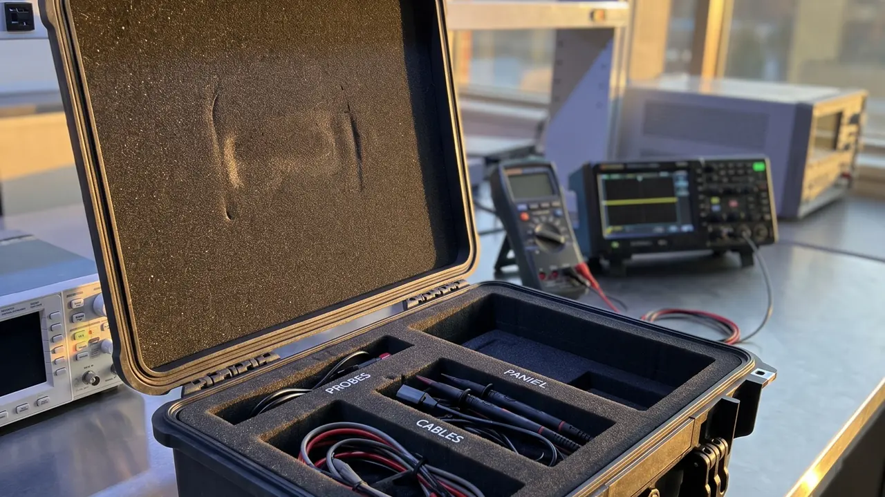
The wheel head assembly and the table represent the two accuracy peaks of a surface grinder, and the transport risks they face are not the same as those of general machine tool components. The short answer: the wheel head must be protected primarily against vibration rather than impact, because spindle bearings develop false brinelling under sustained transport vibration; the head therefore needs full mechanical restraint combined with system-level isolation. Table and guideway surfaces must never be point-loaded or scored, and a magnetic chuck should be demagnetised before packing. The packaging system's natural frequency should sit in the 2 to 4 Hz band so that it falls in the isolation region relative to road-transport excitation. A surface grinder spindle is typically held to a radial runout of about 0.005 mm, and table traverse straightness is commonly assessed at a few thousandths of a millimetre per metre. Accuracy at that level cannot be preserved by simply adding softer foam; it takes deliberate frequency design.
Many problems that appear after a grinder has been shipped are not failures but losses of accuracy: a slight rise in running noise, faint chatter marks on the ground surface, or poorer dimensional consistency during finish grinding. Investigate and the cause usually traces back to sustained vibration in transit, where rolling bearings suffer micro-fretting between rolling elements and raceways — the condition known as false brinelling. The machine still runs, but its accuracy has permanently dropped a grade. This article starts from the vibration mechanism and works through the wheel head, table, guideways, chuck, feed mechanisms and hydraulics, then sets out how to control the packaging system's frequency and how to verify the result.
Contents
- Why a surface grinder is more vibration-sensitive than a general machine tool
- The wheel head assembly: isolating the spindle and bearings
- Grinding wheels and flanges: pack them separately
- Table and guideways: protecting the accuracy datum
- Magnetic chucks: demagnetising and moisture control
- Column and saddle: locking long-travel assemblies
- Feed mechanisms and screws: temporary locking
- Hydraulic and coolant systems: draining before dispatch
- Vibration isolation design: natural frequency and resonance avoidance
- Liners and case stiffness: controlling vibration transmission
- Test references and accuracy acceptance
- Sizing and handling by machine class
- Frequently Asked Questions
- Conclusion and further reading
Why a surface grinder is more vibration-sensitive than a general machine tool
The protection logic only makes sense once the way vibration acts on rolling and sliding interfaces is clear.
Road transport does not deliver a single-frequency harmonic; it delivers broadband random excitation. In practice the dominant energy on a vehicle deck falls into two bands: roughly 2 to 10 Hz from suspension and body modes, and 10 to 25 Hz from wheel and road input. When the packaging system's natural frequency sits inside those bands, the response is amplified. When it sits clearly below them, the system enters the isolation region and transmissibility falls. That is why grinder packaging cannot be solved by piling in more foam — the frequency has to be calculated first.
Spindle bearings are particularly vulnerable to very small reciprocating displacements. An angular contact bearing is assembled with preload, and an extremely thin lubricant film separates ball from raceway. Sustained low-amplitude vibration prevents that film from being maintained, metal contacts metal, and micro-fretting produces dark marks spaced at the rolling element pitch. Nothing is visible when the case is opened; the damage only shows up as noise and chatter once the machine is running.
Guideways face two different threats: scoring and impact on the one hand, corrosion on the other. Sliding guideway mating surfaces are hand-scraped or ground, and once a score breaks the continuity of the oil film, table motion starts to stick and slip.
| Sensitive area | Main damage form | Physical mechanism | Protection direction |
|---|---|---|---|
| --- | --- | --- | --- |
| Spindle bearings | False brinelling, rising noise | Micro-reciprocation destroys the lubricant film | Mechanical restraint plus system isolation |
| Guideway surfaces | Scoring, corrosion, stick-slip | Point contact, condensation, oil film breakdown | Soft protector strips, dry environment |
| Table datum faces | Loss of flatness | Self-weight deflection from inadequate support | Full-length multi-point support |
| Screw and nut | Preload change, stepped feel | Balls circulating under vibration | Temporary support and locking |
| Magnetic chuck | Residual magnetism, damp windings | No demagnetising, high humidity | Demagnetise, desiccant |
| Electrical controls | Zero drift, connector loosening | Shock and sustained vibration | Dedicated sealed cavity, damping pads |
Accuracy loss in a grinder is usually cumulative. Each individual deviation is small, but bearing marks, guideway scores and table distortion add together, and the combined error at the workpiece exceeds tolerance. A case for grinder components therefore has to be designed as a system rather than component by component.
The wheel head assembly: isolating the spindle and bearings
The wheel head is among the most expensive single items on a grinder and the hardest to protect. It contains a precision spindle, a matched pair of preloaded angular contact bearings, a motor and the feed mechanism, and its centre of gravity usually sits toward the motor.
The governing principle is rigid restraint combined with flexible isolation. Rigid restraint means a cavity and clamp plate matched to the head's outline that hold the body so it cannot move at all inside the case. Flexible isolation means the head connects to the case through isolation pads rather than bearing directly on a rigid floor. The two requirements look contradictory but are not: restraint stops the head moving on its own, isolation stops external vibration from reaching it.
In practice the head sits on a 20 to 30 mm isolation pad whose bearing area covers the full width of the head base. A quick-release clamp plate or adjustable bar presses from above, with clamping force set so the head cannot move while pad compression stays below 25 percent. Over-tighten and the pad is crushed, which defeats the isolation; under-tighten and the head shifts inside the case.
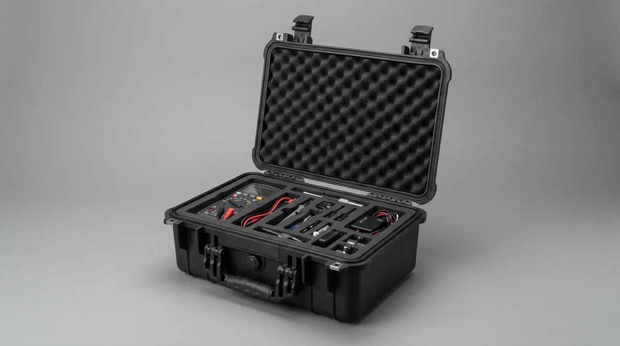
The spindle nose taper or flange locating face must carry a protective cap so it cannot be knocked during loading and unloading. Where head and motor ship assembled, fit a transport lock between them to limit both axial and radial movement. The lock needs a conspicuous removal tag in oil- and heat-resistant material.
A practical way to judge restraint: push the head gently in three directions with both hands and it should not move at all; then tap the case side wall with a fist and the head should show no visible displacement. Any movement during the tap test means restraint is insufficient and more clamping points are needed.
The reasoning behind fixing precision spindle assemblies is set out in CNC spindle component transport protection; a wheel head should be restrained to at least that standard.
Grinding wheels and flanges: pack them separately
A grinding wheel is fragile and thin in section, with very little bending resistance. The main risk in transit is edge impact producing a crack, and cracks typically propagate only later at full rotational speed, which makes them a safety issue rather than a quality one.
A wheel should not share a cavity with the wheel head and should never be laid flat with any load on its faces. The recommended arrangement is upright in a circular pocket machined to the wheel diameter, with pocket depth about two thirds of wheel thickness and a 3 to 5 mm soft layer under the rim. Standing upright lets the wheel's own weight distribute radially instead of pressing on a face.
Flanges, clamping discs and balance weights should be removed and packed separately. Flange mating faces are precision ground, and if they share a cavity with wheels, abrasive dust migrates into those faces under vibration and acts as lapping compound. Store flanges in matched pairs with soft separators, and keep balance weights in numbered compartments.
| Accessory | Transport orientation | Separation requirement | Pre-packing check |
|---|---|---|---|
| --- | --- | --- | --- |
| Grinding wheel | Upright in a circular pocket | 3–5 mm soft layer under the rim | No cracks, no chipped edges, markings legible |
| Flange and clamping disc | Matched pair, stacked | Soft separators, individual pockets | Mating faces free of scoring and rust |
| Balance weights | Numbered compartments | One part per pocket | Numbers and mass markings complete |
| Spindle protective cap | In position | Coaxial with the taper | Cap body undistorted |
| Coolant nozzle | Removed, packed separately | Soft wrapping | Nozzle bore clear |
If a wheel must travel on the machine, fit a rigid guard and leave at least 10 mm clearance between wheel and guard so that vibration cannot bring them into contact.
Table and guideways: protecting the accuracy datum
The table is the accuracy datum of a grinder: its surface flatness and its guideway straightness together determine what the machine can hold. The dominant risk for a member this long remains self-weight deflection caused by inadequate support.
The support rule is continuous bearing along the full length. Lay a full-length bearer strip under the table and place support blocks beneath it at no more than 400 mm centres — tighter than for a general long shaft, because the table is both long and relatively thin-walled. For tables beyond 1000 mm, six or more support points are advisable.
Guideway-face down must be avoided entirely. If the table travels on the machine, move it to mid-stroke, secure it with a mechanical lock, and cover the guideway surfaces with soft protector strips. Choose polyethylene or felt free of plasticiser, because plasticiser migration contaminates the guideway lubricant film.
Rust prevention matters as much as scoring prevention. A hand-scraped sliding guideway has a micro-dimpled texture that retains moisture. Coat it with a thin layer of corrosion-inhibiting grease and wrap it in vapour-phase film before packing. On sea freight the internal humidity target should be tighter still, because a rust spot on a guideway calls for re-scraping, which costs far more than a new liner.
Where the table surface has T-slots or chuck mounting holes, fill them with soft plugs so that slot edges cannot be chipped by loose hardware. Plugs should be slightly longer than the slot for easy removal.
Magnetic chucks: demagnetising and moisture control
Magnetic chucks are standard equipment on surface grinders and are either permanent-magnet or electromagnetic. Two problems arise if they are packed without preparation.
The first is residual magnetism. A chuck retains some magnetism after use, and packing it without demagnetising attracts stray chips and metal dust. Under vibration that dust becomes an abrasive between the chuck face and the liner, scoring the face with fine marks. Electromagnetic chucks should be demagnetised after power-off; permanent-magnet types should have the lever placed in the release position and the face confirmed clear before packing.
The second is moisture. Chuck windings and terminal blocks are sensitive to damp, and on sea freight a high internal humidity can reduce insulation resistance. Fit a moisture cover over the electrical interface, add desiccant inside the case, and wrap the chuck in corrosion-inhibiting film.
A chuck is large in area and thin in section, so when laid flat its supports should run diagonally rather than sitting under the four corners, which would leave the middle spanning. Where the section is thin enough that stiffness is limited, mount the chuck on a wood or engineering-plastic backing board and pack the assembly as one item.
Column and saddle: locking long-travel assemblies
The column and saddle carry the wheel head in vertical and cross travel. They are motion-pair assemblies: long travel, many mating surfaces, and free movement unless restrained.
The approach resembles that used for blade beams, with more emphasis on parking at a safe position. Before packing, move column and saddle to a position slightly below mid-travel so the centre of gravity sits near the case centre, then secure with mechanical lock blocks used in pairs so that both directions of movement are limited.
If column and saddle ship separately, remove the saddle and restrain it on its own, because the saddle usually sits high with a raised centre of gravity and any movement during transport puts impact directly into the column guideway. A separated saddle needs its guideway mating surfaces wrapped and its own individual pocket.
Guideway protector faces and gibs are wear items on the saddle. A gib — the tapered strip that sets clearance — loosens readily under vibration and should be tightened and secured against loosening before packing. A gib that falls out means the clearance has to be re-set on site, which is pure added labour.
Feed mechanisms and screws: temporary locking
Vertical and cross feed on a surface grinder normally uses a screw-and-nut mechanism, and higher-precision machines may use ball screws or worm drives. All share very small running clearances and sensitivity to vibration-induced fretting.
A ball screw is handled correctly in three ways: keep the preload, add mid-span support, and limit axial movement. Keeping preload means the nut stays assembled to the screw at its working preload rather than being separated and laid loose. Mid-span support means fitting a temporary cradle so that self-weight cannot bow the screw and alter preload. Limiting axial movement means fitting stops at both ends so the screw cannot shuttle inside its bearing housings.
Worm drives need two precautions: the worm's axial position is set by bearing preload and must not take axial impact, and the worm wheel contact zone must be kept free of foreign matter, which means soft wrapping.
Handwheels and dials are exposed and easily damaged. Where they cannot be removed, fit a guard; where they can, remove them for separate packing and fit a dust plug over the shaft bore so that dust cannot enter the case interior.
Hydraulic and coolant systems: draining before dispatch
The hydraulic system drives table reciprocation and typically includes a reservoir, pump set, valve block and cylinder. The coolant system includes the coolant tank, pump and pipework.
The core action for hydraulics is drain and plug. Fluid inside the table cylinder migrates from one chamber to the other as the machine tilts, and with open ports it will seep out and form an oil film across the case. Drain the cylinder, plug the ports, and lay an absorbent layer underneath. Treat the valve block and reservoir separately: the block goes into its own sealed packaging, and the drained reservoir is secured on its own.
Coolant is harder to deal with. Coolant — emulsion or synthetic — contains water and additives, and leakage accelerates corrosion of every steel item in the case while residual fluid in a sealed case can produce odour and mould. The correct approach is to drain the tank completely, flush with clean water, allow it to dry, remove and pack the pipework separately, and plug every nozzle bore.
Components retaining liquid may also face transport compliance restrictions; the classification logic is discussed in compliance assessment for cases containing liquids.
After the coolant tank and pipework are processed, inspect the case interior as a whole: no residual liquid, no unplugged ports and no loose gaskets. Where the same case also carries precision items such as the wheel head, put a solid divider between the two so that any leakage path cannot lead directly into the precision cavity.
If the hydraulic pump and motor ship assembled, fit a transport lock between pump and motor shafts and blank off the pump suction port. Every removed fitting needs a plug matched to its thread; cotton waste or tape is never an acceptable substitute.
Vibration isolation design: natural frequency and resonance avoidance
The decisive difference between grinder packaging and packaging for most other equipment is that the packaging system has to be designed as a vibration system rather than made thicker.
The underlying relationship is simple. A packaging system approximates a mass-spring-damper, and its natural frequency follows from support stiffness and packaged mass. When the ratio of excitation frequency to natural frequency exceeds the square root of two, the system is in the isolation region and transmissibility falls below one. As the ratio approaches one, resonance amplifies transmissibility sharply. The design target is therefore a natural frequency well below the dominant excitation.
On road transport, the deck excitation energy concentrates between 2 and 10 Hz. A packaging system tuned to 2 to 4 Hz achieves a frequency ratio of 2 to 5, comfortably inside the isolation region. A system whose natural frequency lands between 6 and 10 Hz is close to resonance, where vibration is amplified rather than attenuated — the most dangerous state for spindle bearings.
| Natural frequency | Relation to 2–10 Hz excitation | Transmissibility behaviour | Suitability |
|---|---|---|---|
| --- | --- | --- | --- |
| 2–4 Hz | Below the excitation band | Isolation region, transmissibility below 1 | Recommended for precision assemblies |
| 4–6 Hz | Lower edge of the excitation band | Transmissibility near 1, limited attenuation | Acceptable with additional damping |
| 6–10 Hz | Inside the excitation band | Possible resonant amplification | Avoid |
| Above 10 Hz | Above the excitation band | Isolation lost, near-rigid transmission | Unsuitable for precision parts |
Three levers produce a low natural frequency: reduce support stiffness by using softer and thicker isolation pads, raise damping by choosing high-damping materials such as polyurethane or butyl rubber, and control mass distribution so that load is not concentrated locally. They must be used together, because reducing stiffness alone produces excessive static compression and lets the head shift inside the case.
There is a trade-off between static compression and natural frequency: softer pads lower the frequency but increase deflection under load. As a rule, isolation pads should compress by 10 to 25 percent of their thickness under static load while also meeting the frequency target. If both cannot be satisfied, switch to a lower-stiffness material with better recovery, or adopt a hybrid of local isolation plus overall restraint.
Liners and case stiffness: controlling vibration transmission
The liner plays three roles in vibration control: locating the part, damping the response, and tuning the frequency.
For the contact layer, choose a low-hardness, high-damping material. Polyurethane and butyl rubber have higher damping ratios than ordinary EVA and suppress resonant peaks more effectively. A thickness of 3 to 8 mm works well: thinner than that and damping is negligible, thicker and location accuracy suffers.
The locating layer holds the part in place, and cavity clearance should be held to 1 to 2 mm. Too much clearance gives the part room to move, which turns into secondary impact under vibration; too little makes loading difficult and risks scoring mating faces during handling.
The load-spreading layer distributes load, and its stiffness directly affects the system's natural frequency. The stiffer it is, the higher the frequency, so for wheel heads an over-stiff layer works against the objective. Cavity depth, draft angle and finger relief values are discussed in precision instrument case selection and liner configuration.
The case itself also transmits vibration. A rotationally moulded case has thick walls and high stiffness, which protects the contents structurally but raises the system frequency; compensate by thickening the isolation pads. How cushioning layers work with case structure is covered in cushioning liners and case structure.
For heads with the tightest accuracy requirements, a case-within-a-case arrangement is worth considering: the head is fixed in an inner case, which is then suspended on isolation pads inside the outer case. This lowers the system frequency markedly but adds bulk and cost, so reserve it for machines at the higher end of the accuracy range.
Test references and accuracy acceptance
Verification for a grinder case runs on two tracks — packaging testing and machine accuracy acceptance — and neither can be dropped.
On packaging, the vibration and drop tests in the GB/T 4857 series matter most. Vibration testing should use random rather than fixed-frequency sinusoidal excitation, because real transport is broadband random. Drop testing verifies corner impact resistance and the adequacy of the head restraint. The ISTA series offers sequences closer to a real distribution chain, while ASTM D4169 combines test intensities into a distribution cycle. How such cycles are cited is explained in citing the ASTM D4169 distribution cycle.
On environmental performance, the high-temperature, low-temperature, humidity and vibration methods in MIL-STD-810H can be cited as method references. To be explicit about a point that is frequently misread: MIL-STD-810H serves here only as a source of environmental test methods. It is not a military certification and does not represent military product qualification. A technical agreement citing it should also state the method number, the procedure number and the test intensity, otherwise the resulting report cannot be used for a pass or fail decision.
For machine accuracy, GB/T 9061 (general specification for metal cutting machine tools) provides the accuracy inspection approach used as the datum convention, allowing table flatness, guideway straightness and spindle runout to be checked back against factory values after reassembly. Thermal cutting and blanking tolerances can reference ISO 9013, and metal forming component accuracy can reference GB/T 23281.
| Verification item | Reference | Typical criterion | Note |
|---|---|---|---|
| --- | --- | --- | --- |
| Packaging random vibration | GB/T 4857 series | Spectrum and duration as agreed | Random excitation preferred |
| Packaging drop | GB/T 4857 series | Drop height by mass class | Cover corners, edges, faces |
| Distribution cycle | ASTM D4169 | DC level and assurance level | Common on export projects |
| Environmental testing | MIL-STD-810H | Method and procedure must be stated | Not a military certification |
| Accuracy inspection | GB/T 9061 | Flatness, straightness, runout | Checked after reassembly |
| Enclosure rating | GB/T 4208 / IEC 60529 | IP54 or IP67 | Selected by transport environment |
Acceptance is best run in four steps: unpacking inspection, static measurement, no-load running, and test grinding. Unpacking covers appearance and restraint condition. Static measurement checks geometric accuracy. No-load running checks noise and temperature rise. Test grinding uses a standard workpiece to verify surface roughness and waviness. Only when all four pass can the absence of transport-induced accuracy loss be confirmed.
Sizing and handling by machine class
Surface grinders range from small 200 × 400 mm machines to large units beyond 800 × 2000 mm, and component masses vary accordingly. Wheel heads typically run 60 to 400 kg, tables 80 to 600 kg, and column-and-saddle assemblies 300 to 900 kg.
| Component | Typical mass | Suggested case | Liner focus | Handling |
|---|---|---|---|---|
| --- | --- | --- | --- | --- |
| Wheel head assembly | 60–400 kg | Mid-size or heavy case | Isolation pads plus quick-release clamp | Forklift or crane |
| Table | 80–600 kg | Long pallet case | Full-length bearer, dense supports | Forklift |
| Column | 150–500 kg | Heavy case | Full enveloping cavity, multi-axis locks | Crane |
| Saddle | 80–300 kg | Mid-size case | Guideway protector strips, individual pockets | Forklift |
| Magnetic chuck | 30–200 kg | Flat case | Backing board, diagonal supports | Two-person lift or crane |
| Wheels and accessories | 5–50 kg | Compartment case | Circular pockets, soft layers | One person |
Beyond mass, verify case stiffness under stacking. Grinder cases should not be cross-stacked; stack identical cases in the same orientation and state the maximum number of layers. Long cases benefit from external full-length reinforcing bars or an integral steel base frame.
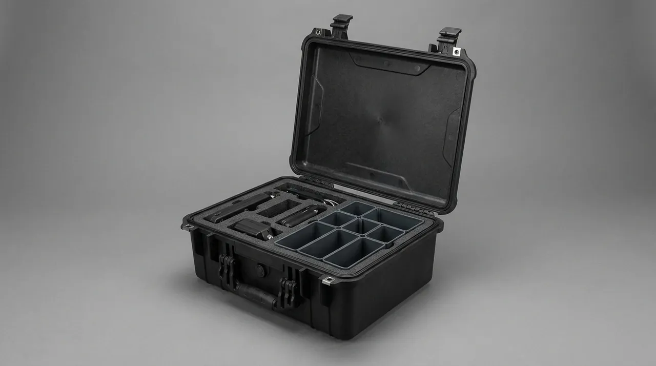
Handling information must be marked on the case: lifting points, centre-of-gravity projection, no-roll and no-invert. Cases containing a spindle should also carry shock and tilt indicators so that an over-limit event can be identified on arrival.
One point deserves emphasis: there is almost no such thing as a universal grinder case. The same wheel head with ordinary angular contact bearings and with hydrostatic bearings has completely different isolation requirements, and two tables of the same size but different wall thickness need different support spacing. The JUNZHIJIA brand is produced by Kexin New Materials (Guangdong) Co., Ltd., which in the surface grinding sector builds wheel head cases, long table cases and flat chuck cases to customer drawings, integrating isolation material selection, cavity milling and case structure in one design. Supply runs through wholesale, distribution and direct worldwide shipment, material and inspection documentation is available by contract, and OEM or ODM projects can be branded to the customer's identity. For supplier evaluation, the capability checklist in how to assess a protective case OEM factory is a useful reference, and where a new cavity requires tooling, custom case tooling cost analysis helps set tooling cost against batch size.
Frequently Asked Questions
Q: Why can a surface grinder not travel in an ordinary cushioning case?
A: Because the failure mode here is vibration damage rather than impact damage. An ordinary cushioning case is designed to absorb drop shock and is judged on peak acceleration. A surface grinder is damaged mainly by sustained random vibration lasting many hours, which prevents the lubricant film in the spindle bearings from being maintained and produces micro-fretting and false brinelling. The case therefore has to be treated as a vibration system: tune its natural frequency into the isolation region relative to the excitation band and add high-damping material to suppress resonant peaks. Simply adding thicker foam can raise the system frequency into the resonance band, making the outcome worse than before. The two requirements are also judged differently: drop performance is measured by peak acceleration recorded during a test, while vibration performance is judged by the frequency response of the packed assembly. A case can score well on the first and fail badly on the second, so ask the supplier which of the two the design was optimised for.
Q: What natural frequency should the packaging system be tuned to?
A: Aim for 2 to 4 Hz. Deck excitation on road transport concentrates between 2 and 10 Hz, and when the packaging system's natural frequency sits clearly below that band, the frequency ratio exceeds the square root of two, the system enters the isolation region and transmissibility drops below one, so vibration is attenuated rather than amplified. If the natural frequency lands between 6 and 10 Hz it sits close to resonance and vibration is amplified, which is the worst case for spindle bearings. Frequency follows from support stiffness and packaged mass, and can be tuned by reducing stiffness, adding damping, and controlling mass distribution. Keep static compression of the isolation pads within 10 to 25 percent of their thickness. Measure the frequency rather than assuming it: a resonance search on a shaker, sweeping the packed case through the band of interest while monitoring accelerometers mounted on the component, shows where the system actually sits and whether a pad change is needed before the design is frozen.
Q: Should the wheel head be locked solid or left with some cushioning?
A: Both, but they do different jobs. The head body must be restrained rigidly by a matched cavity and clamp plate so it cannot move at all inside the case. At the same time the head connects to the case through isolation pads, which keeps external vibration from reaching it. Restraint stops the head moving on its own; isolation stops external vibration coming in — they are complementary rather than contradictory. Set clamping force so the head cannot move while pad compression stays under 25 percent. Clamp it too hard and the pad is crushed and stops isolating; clamp too lightly and the head shifts inside the case and produces secondary impact under vibration. Run the tap test at every packing, not only at the prototype stage, because a technician under time pressure will sometimes substitute a different pad thickness. Write the pad specification and the clamping torque on the inside of the case lid so that the intended configuration is unambiguous.
Q: Can the grinding wheel be left on the wheel head for transport?
A: It is not the preferred arrangement. A grinding wheel is a thin disc with very little bending resistance, and edge impact during vibration can create a crack that is difficult to see. Such cracks typically propagate only at full rotational speed, which makes them a safety issue rather than a cosmetic one. Remove the wheel and stand it upright in a circular pocket machined to its diameter, with the pocket about two thirds of the wheel thickness deep and a 3 to 5 mm soft layer under the rim. If the wheel must travel on the machine, fit a rigid guard and leave at least 10 mm of clearance between wheel and guard so that vibration cannot bring the two into contact. Label the guard so it is not mistaken for a shipping brace and removed before dispatch. A wheel should also carry its maximum permissible speed clearly marked, since a wheel that has travelled separately is often refitted by a different team from the one that removed it.
Q: What preparation does a magnetic chuck need before packing?
A: Two things matter: demagnetising and moisture control. For demagnetising, switch off an electromagnetic chuck and run the demagnetising cycle, or set a permanent-magnet chuck's lever to the release position and confirm the face is clear. Packing without demagnetising attracts stray chips and metal dust, and under vibration that dust acts as an abrasive between the chuck face and the liner, scoring the face with fine marks. For moisture, protect the windings and terminals with a cover and add desiccant inside the case, because a high internal humidity on sea freight can reduce insulation resistance. Because a chuck is broad and thin, run its flat supports diagonally rather than under the four corners, which leaves the centre spanning. Never lift a chuck with slings threaded through its bore, because the bore edge is a machined reference surface and a sling under load will mark it. Use a lifting plate bolted to the mounting holes instead, and record the residual magnetism reading before dispatch where the customer's process is sensitive to it.
Q: How does table support spacing differ from that used for blade-like long components?
A: Table supports should be closer together, no more than 400 mm apart, against 500 mm for blade-type components. The reason is that although a table looks substantial, it is often a relatively thin-walled structure and is also the accuracy datum, so its bending resistance is limited and any deflection directly affects surface flatness. For tables beyond 1000 mm, six or more support points are advisable. Laying a full-length bearer strip under the table and placing spaced blocks beneath it works better than resting the table directly on separate blocks, because it evens out the load and avoids a local high point leaving a mark on the surface. Note that the 400 mm figure assumes uniform mass distribution along the table. If the table carries a heavy attached item such as a chuck or a taper attachment, position the support blocks so the centre of gravity sits between two blocks rather than directly over one, and confirm the spacing after a trial loading rather than before.
Q: How should guideway surfaces be prepared before packing?
A: Work through clean, coat, wrap and control humidity. Clean the surfaces with a lint-free cloth and remove all swarf. Apply a thin, even layer of corrosion-inhibiting grease, remembering that a hand-scraped surface has a dimpled texture that retains moisture, so an over-thick layer simply traps water. Wrap with vapour-phase corrosion-inhibiting film, keeping the distance from the wrapped surface to the film within 300 mm. Then add desiccant and keep the case's moisture transmission rate low. A rust spot on a guideway means re-scraping, which costs far more than a replacement liner, so humidity control on sea freight is money well spent. Where the machine will be stored for a long period before installation, refresh the desiccant at intervals rather than relying on a single charge to last the whole period, and record the humidity inside the case at each inspection so that trends become visible. A cheap humidity indicator card inside the lid turns those checks into a ten-second job.
Q: Can MIL-STD-810H be used as a pass criterion for grinder packaging?
A: It can be cited as a method reference but not as a qualification criterion. In this industry MIL-STD-810H supplies methods and procedural parameters for high temperature, low temperature, humidity, vibration and shock; citing it settles how a test is run and how severe it is. The standard is not a military certification and does not represent military product qualification. Any technical agreement referencing it must also state the method number, the procedure number, the test intensity and the duration, because without those details a completed test cannot be judged pass or fail. Where a customer genuinely requires qualification, that is a separate programme with its own documentation set. In practice this matters most during tendering, when a specification may be copied from an earlier project. If the requirement is genuinely environmental testing, ask for the method and procedure numbers at the quotation stage and put them in the purchase order, so that the test house and the supplier are working to the same document. Doing this later usually means retesting.
Q: How should grinder components be inspected on arrival?
A: Use four steps: unpacking inspection, static measurement, no-load running, and test grinding. Unpacking covers appearance, restraint condition and whether any indicator has triggered. Static measurement checks table flatness, guideway straightness and spindle radial runout against factory values. No-load running checks noise level and bearing temperature rise. Test grinding uses a standard workpiece to verify surface roughness and waviness. If any step is abnormal, carry out an accuracy re-check before deciding whether to install the machine; do not reassemble first and investigate afterwards, because reassembly itself can obscure the original evidence of vibration damage. Photographs taken at dispatch, showing the restraint condition and any indicator reading, are the cheapest form of evidence if a dispute arises. Keep them with the packing list so the receiving team can compare the as-shipped state with what they find on opening. A short video of the tap test takes seconds and settles most arguments about restraint. File the photographs by case number rather than by project, because the same case will be reused across several machines and the comparison only works when its history stays with it.
Conclusion and further reading
The design priorities for a surface grinder case come down to three statements: isolate the wheel head as a system rather than by adding foam, support the table and guideways along their full length rather than at a few points, and handle the chuck and electrical items through demagnetising and humidity control rather than appearance alone. Tuning the packaging system's natural frequency into the 2 to 4 Hz isolation band is the single most important step and the one most often skipped, because it decides whether vibration is attenuated or amplified.
When specifying, provide the component list and masses, the transport mode and route, the natural frequency target for the packaging system, and the acceptance criteria in one package so the manufacturer can select isolation materials and case structure accordingly. On higher-accuracy machines it is better to settle the split-shipment arrangement while the machine is still being designed, so that the removability and protection requirements of the wheel head, table and chuck are designed in rather than retrofitted to an existing structure.
Further reading