

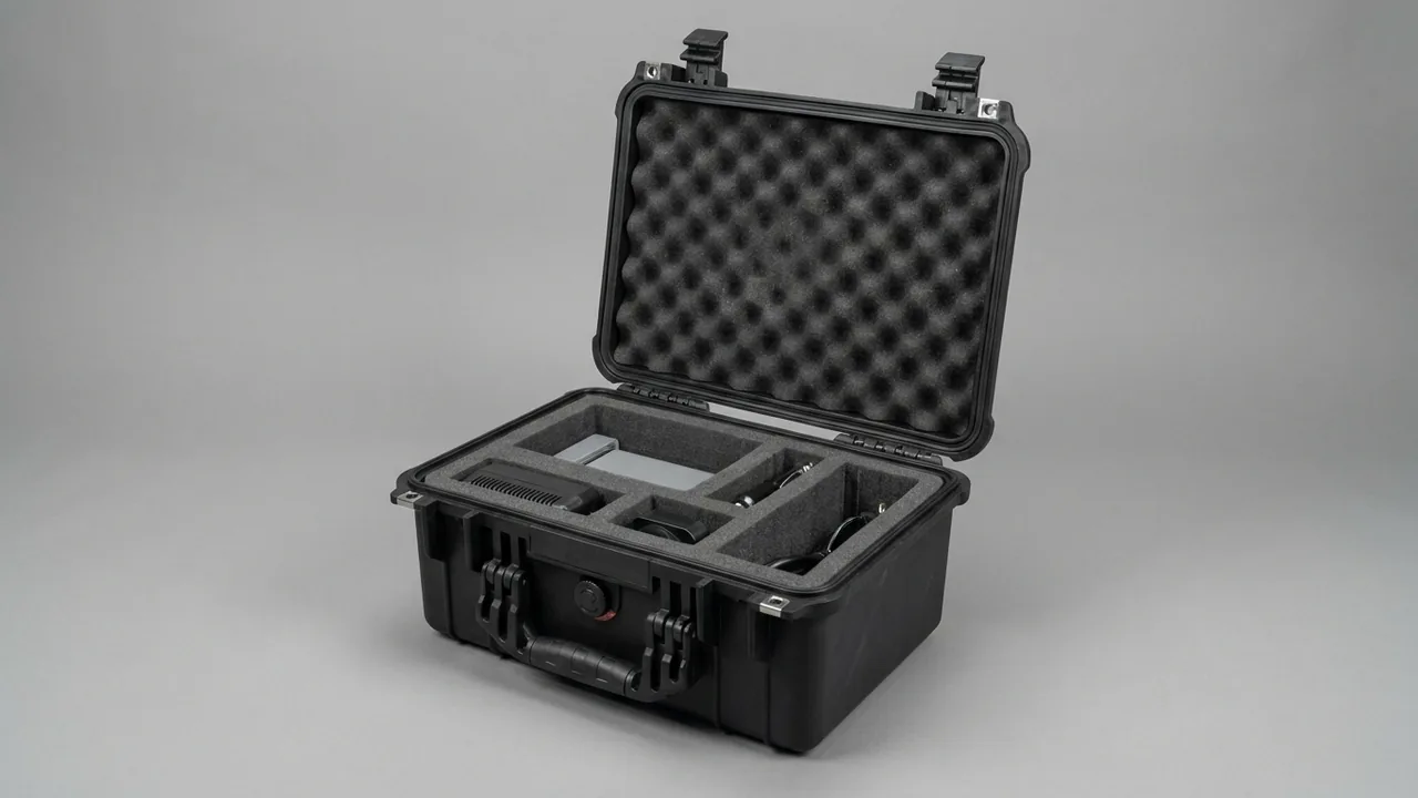
The electrodes and dielectric system of an electrical discharge machine impose two constraints that most machine tool packaging never faces — cleanliness and vibration isolation — and the two frequently pull in opposite directions. The short answer: electrode formed surfaces must be protected on a zero-contact basis, so no pad, sleeve or divider may rest on them; graphite and copper electrodes need two entirely separate packing methods, because one sheds conductive powder and the other dents easily; and the dielectric compartment must be physically separated from every electrode compartment, since graphite dust conducts electricity and will cause short circuits and contamination if it reaches the fluid circuit or the electrical assemblies. EDM accuracy rests on stable control of the spark gap, and that gap is measured in tens of micrometres. A single 0.02 mm impression on a formed surface can put the cavity out of tolerance, and no amount of parameter adjustment will recover it.
There is a second failure pattern that is easy to underrate: equipment that arrives apparently undamaged but will not perform. Graphite powder shed in transit can settle on a copper electrode or on a holder locating face, and once the machine is running it produces unstable discharge and abnormal spotting on the work surface. Similarly, old dielectric fluid left in the tank mixes with fresh fluid and degrades both filtration performance and dielectric strength. None of this is obvious when the case is opened, yet all of it surfaces during the trial machining stage. This article works through electrodes, holders, spindle head, dielectric system, power supply and dust control in turn, with practical packing methods, cleanliness requirements and acceptance criteria.
Contents
- Two constraints that set EDM component packaging apart
- Electrodes: the zero-contact rule for formed surfaces
- Graphite and copper electrodes: two materials, two methods
- Electrode holders and changers: protecting locating faces
- Spindle head and C axis: locking precision rotary assemblies
- Dielectric system: fluid, filtration and deionising resin
- Power supply and pulse generator: moisture and dust protection
- Conductive dust control: containing graphite powder
- Liner materials: ESD-safe, non-shedding, cleanable
- Case sealing and cleanliness class
- Transport testing and cleanliness acceptance
- Sizing and handling
- Frequently Asked Questions
- Conclusion and further reading
Two constraints that set EDM component packaging apart
The first constraint is cleanliness. EDM is a precision micro-removal process in which surface quality and spark gap stability depend jointly on fluid cleanliness, electrode surface condition and the insulation state of the electrical circuit. Dust, oil and moisture introduced in transit all translate into unstable discharge after commissioning.
The second is vibration, though the mechanism differs from that affecting a grinder. A grinder suffers because bearings develop false brinelling. An EDM machine suffers mainly because electrodes are thin-walled, complex or slender structures with limited bending and torsional resistance, so the reciprocating inertial forces of vibration produce micro-plastic deformation at the points where they are supported. The spindle head and C axis motion pairs are vibration-sensitive for the same reason as any precision assembly.
The two constraints conflict. Improving cleanliness argues for a sealed case, and a sealed case traps moisture. Suppressing vibration argues for soft liners, and soft liners shed particles and attract dust. The answer is not compromise but zoning: put components of different cleanliness classes and different vibration sensitivity into separate compartments, each with materials suited to its own requirement.
| Component class | Cleanliness class | Vibration sensitivity | Main failure form | Compartment strategy |
|---|---|---|---|---|
| --- | --- | --- | --- | --- |
| Copper electrode | High, dust-free | Medium | Surface scoring, thin-wall distortion | Own compartment, soft contact layer |
| Graphite electrode | Very high, no cross-contamination | Medium-high | Edge chipping, powder dispersal | Own sealed compartment, ESD-safe |
| Electrode holder | High | High | Locating face scoring, accuracy drift | Own compartment, hard pocket |
| Spindle head and C axis | High | Very high | Bearing marking, motion pair wear | Own compartment, isolated mounting |
| Dielectric pump and valves | Medium | Medium | Fluid seepage, seal ageing | Own compartment, absorbent layer |
| Power supply and drives | High, moisture-sensitive | High | Damp ingress, connector loosening | Own compartment, desiccant |
| Filters and resin | Medium | Low | Moisture caking, contamination | Own sealed bag |
Once zoned, the case interior becomes a set of separate micro-environments, each with its own humidity, cleanliness and restraint conditions. This is considerably more reliable than one large cavity with a few dividers, and it also makes acceptance testing straightforward to perform item by item.
Electrodes: the zero-contact rule for formed surfaces
An electrode is the tooling that directly determines the machining result. Its formed surface is where the discharge occurs and it usually carries the tightest dimensional tolerance on the whole electrode. The first principle of electrode protection can be stated in one line: the formed surface must not touch anything, including the softest material available.
The reasoning is not complicated. Any object pressing on a formed surface creates local plastic deformation around the contact point, and copper has a low hardness and therefore a low threshold for it. Once the surface deforms, the spark gap at that location changes, and the machined cavity carries a mark at the corresponding position. Electrode support must therefore land on non-formed features — the datum face, the mounting shank or a purpose-made process boss.
In practice the sequence is to identify the datum face and process bosses first and design the cavity around them. Cavity-to-datum fit uses a small clearance of 0.05 to 0.1 mm for location, while the formed surface side is left with 3 to 5 mm of air and receives no liner material at all. Retention inside the cavity comes from the datum restraint plus a soft clamping bar from above, and that bar may only press on non-formed surfaces.
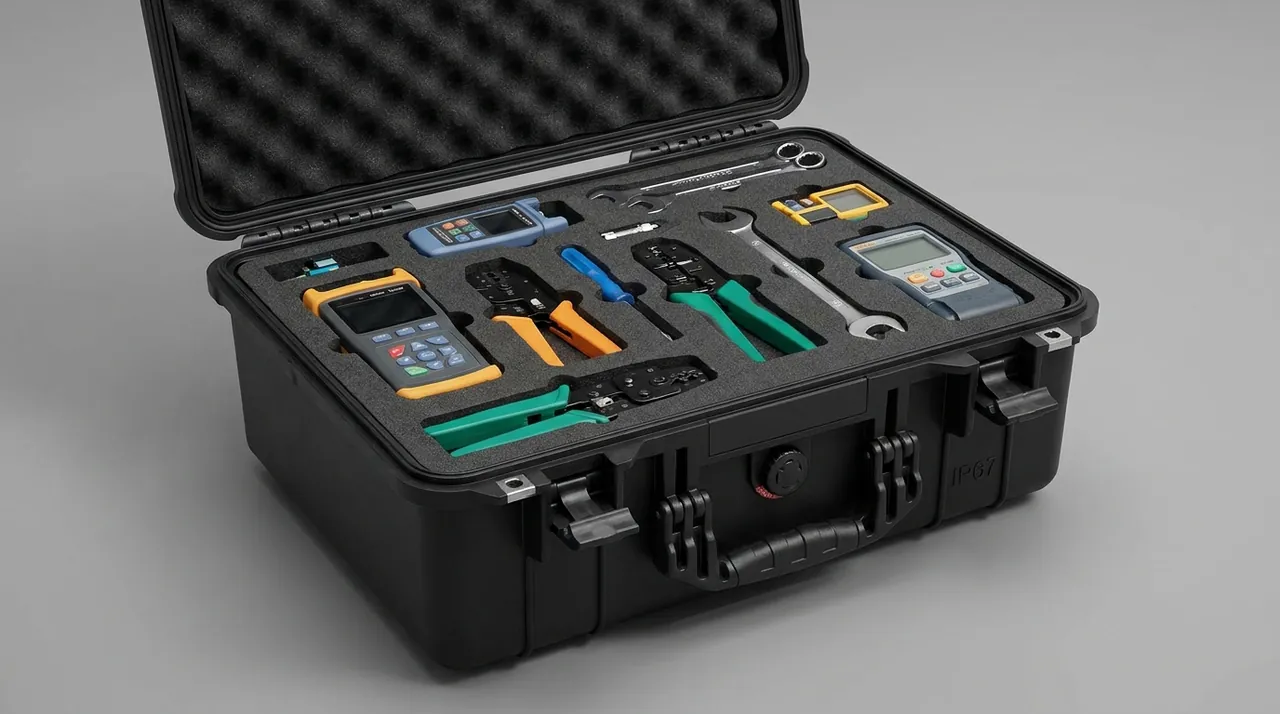
Slender and thin-walled electrodes need more. A slender electrode should have additional supports along its length, again landing only on non-formed surfaces, spaced according to the electrode's section moment of inertia and typically no more than 300 mm apart. A thin-walled electrode can be braced internally with a removable process strut that holds the walls apart during transport and is taken out before commissioning. Every process strut needs a conspicuous tag so it cannot be left in place.
A practical test: once packed, the formed surface should be entirely unsupported. Tilt the case to 30 degrees and return it to level, then check whether any contact mark has appeared. If the formed surface touched anything during the tilt, the cavity design needs revision.
Where an electrode has a mirror-finish requirement, the contact layer can be a non-woven or microfibre cloth, but the cloth must be free of plasticiser and loose fibre. A cloth that sheds fibre leaves strands attached to the electrode surface, and those become discharge initiation points after commissioning.
Graphite and copper electrodes: two materials, two methods
Graphite and copper are the two main electrode materials in EDM, and their properties differ enough that packing methods must diverge.
Graphite is brittle, low in density and sheds powder readily. Failure is dominated by edge chipping and surface flaking, and the powder it sheds conducts electricity and contaminates other components and electrical assemblies in the same cavity. Graphite electrodes therefore belong in their own sealed compartment with an ESD-safe interior and a replaceable powder collection mat in the base. Handle graphite with clean gloves, because skin oils change surface wettability and can affect subsequent discharge stability.
Copper is soft, ductile and prone to scoring and distortion. Failure is dominated by scoring, impression marks and thin-wall buckling. Copper electrodes also travel in their own compartment, but the emphasis is on contact protection rather than dust: every cavity surface that could touch the electrode should be radiused, and no sharp edges should exist. Location should come from the datum face rather than from clamping.
| Comparison | Graphite electrode | Copper electrode |
|---|---|---|
| --- | --- | --- |
| Main failure form | Edge chipping, surface flaking, powder shedding | Scoring, impression marks, thin-wall distortion |
| Particulate risk | High, and conductive | Low, occasional copper chips |
| Compartment requirement | Sealed, ESD-safe, powder mat | Own compartment, all edges radiused |
| Retention method | Datum pocket plus soft upper clamp | Datum pocket, avoid clamping |
| Cleaning method | Dedicated vacuum extraction, never blow-off | Lint-free cloth wipe |
| Surface sensitivity | Oil and dust | Scoring and oxidation |
One cleaning rule deserves emphasis. Never blow graphite electrodes clean with compressed air. Blowing disperses graphite powder across the whole working area and makes contamination worse rather than better. Use a dedicated vacuum with filtration and a soft nozzle, and keep the nozzle clear of the electrode edges to avoid knocking material off them.
The two materials should not share a case. Even with a divider, graphite powder migrates through gaps and ends up on the copper. Where sharing is genuinely unavoidable, place graphite electrodes in a sealed box below the copper electrodes so that powder migrates downward, and add a sealing membrane between the two layers.
Electrode holders and changers: protecting locating faces
The electrode holder connects the electrode to the spindle, and its locating accuracy governs the repeat positioning accuracy of the electrode on the machine. Holders typically use a taper, a face or a spherical locating feature, all finish-machined to high hardness and flatness; a score on any of them produces a repeat-positioning error.
The priority is isolating the locating faces. Fit a dedicated sleeve or cap over the taper and face features, then seat the assembly in a hard pocket. Choose POM or nylon — a hard engineering plastic — rather than soft foam, because soft material is cut into by the sharp edge of a locating face under vibration, which leaves the pocket loose rather than tight.
An electrode changer is a multi-station mechanism containing an indexing structure and several electrode seats. Its risk points are the indexing locating faces and the locking mechanism. Before packing, lock the indexer at a defined station and secure the locking mechanism against loosening. Where seats are removable, take them off and pack them by number, capping their positions on the body against dust.
Because holders and seats come in families of identical items, compartmentalised packing suits them well, but the compartment logic differs from general machine parts: every locating face must remain untouched, so pocket design should create clearance referenced to the datum rather than achieving a tight wrap.
Spindle head and C axis: locking precision rotary assemblies
The spindle head carries the Z-axis servo motion, and the C axis provides rotary indexing of the electrode. Both are precision motion pairs and both are sensitive to vibration and to contamination.
The approach to the spindle head resembles that used for a grinder wheel head, but the emphasis shifts. A wheel head is chiefly at risk of micro-fretting in its bearings; a spindle head has the additional risk of a linear guide carriage creeping back and forth without preload. Before packing, put the motion pairs into a preloaded or locked state: fit transport locks on the linear guides, add a temporary support under the screw, and fit an indexing lock pin on the rotary axis.
For the C axis the requirement is angular hold. If the axis drifts in transit, the zero point has to be recalibrated on site, which is avoidable labour. Rotate the axis to its mechanical zero, secure it with the lock pin, and mark the pin position and removal method on the outside of the case.
The electrode clamping end of the spindle — chuck or collet — needs a protective cap so it cannot be knocked during loading. Its taper and face are precision locating surfaces and deserve protection at least equal to that given to the electrode holders.
Cases containing a spindle head should carry shock and tilt indicators. Once a component of this kind has taken an over-limit impact its appearance is usually unchanged while its accuracy may not be, so an indicator provides the trigger for an accuracy re-check.
Dielectric system: fluid, filtration and deionising resin
The dielectric system includes the fluid tank, pumps, valves, filters and the deionising resin unit. The dominant risk here is not mechanical damage but residual fluid and contamination.
The fluid tank must be drained completely. EDM dielectric is usually mineral-oil based or synthetic, and fluid left in place accumulates and attracts dust, forming sludge that is very hard to remove. After draining, rinse once with a dedicated cleaner or with the same grade of fresh fluid, then allow it to dry thoroughly. Fit gasketed plugs to the drain and return ports; tape or cotton waste is not an acceptable substitute.
Pumps and valve blocks need plugging and absorbent protection. Plug the pump inlet and outlet and every valve port, and lay an absorbent layer underneath. If a small amount of fluid does escape in transit, the layer keeps it local instead of letting it spread into the electrode compartments.
Deionising resin and filters are consumables whose main transport risk is moisture and contamination. Seal the resin in a bag with desiccant, and keep filters in their original packaging so they do not adsorb dust inside the case. Used resin should be logged for service hours and handled under the applicable waste rules; it must not travel across borders in a case.
| Dielectric component | Action before packing | Placement in case | Check before commissioning |
|---|---|---|---|
| --- | --- | --- | --- |
| Fluid tank | Drain, rinse, dry | Own compartment, ports plugged | No sludge, no odour |
| Pump set | Drain, plug, lock shaft | Own compartment, absorbent layer below | No seepage, shaft turns freely |
| Valve block | Plug every port | Own compartment, individual pocket | No spool sticking |
| Filters | Keep original packaging | Sealed bag with desiccant | Element dry and undamaged |
| Deionising resin | Sealed bag with desiccant | Own compartment, no stacking load | No caking, no contamination |
| Pipework and fittings | Remove, plug each item | Compartmentalised by length | Ports undistorted, none missing |
Dielectric components and electrodes must never travel in the same compartment; there is no exception to this. Residual fluid combined with graphite powder forms conductive sludge whose effect is far worse than either contaminant alone. Handling approaches for fluid-bearing compartments are discussed in water treatment equipment component protection.
Power supply and pulse generator: moisture and dust protection
The pulse generator, drive units and control boards are the electrical core of an EDM machine, and all three share the same weaknesses: moisture, dust and electrostatic discharge.
Moisture control comes first. Board-level and high-voltage components lose insulation resistance in damp conditions, and condensation inside a sea container is the main source. Fit adequate desiccant in the electrical compartment and protect boards with a conformal coating or a moisture barrier bag. The case should carry a pressure equalisation valve so that the gasket is not sucked open by a pressure differential.
Dust control focuses on graphite powder and metal chips. Conductive dust settling on a board creates a creepage path and can cause a short circuit in the worst case. The electrical compartment must therefore be fully isolated from the electrode compartments, with filter pads or sealing on every cable entry and ventilation opening.
Static control is the third requirement. In a dry environment a board accumulates static charge readily during handling. Pack boards in ESD bags, use ESD-safe lining inside the compartment, and require operators to wear grounded wrist straps. General practice for static-safe packaging is covered in ESD shielding cases for precision components, and bundling and retention methods for board-level items are described in PCB transport case selection.
| Electrical item | Main risk | Protection | Acceptance point |
|---|---|---|---|
| --- | --- | --- | --- |
| Pulse generator unit | Damp ingress, dust through vents | Moisture bag, filter pads, desiccant | No condensation marks, vents clear |
| Drive units and boards | ESD, vibration loosening | ESD bag, damping pad, connector locks | Bags intact, no pin deformation |
| Transformers and inductors | Moisture, core movement | Moisture barrier wrap, full restraint | Core not displaced, no rattle |
| Terminals and harnesses | Connector loosening, oxidation | Terminal caps, harness restraint | Terminals clean, none missing |
| Sensors and encoders | Crushing, zero drift | Individual recess, rigid guard | Sensing faces unmarked |
Electrical compartment lids are best fitted with reusable latches so that desiccant condition can be checked after every trip. For long-term storage, replace desiccant on a schedule and log the readings.
Conductive dust control: containing graphite powder
Graphite powder control is what distinguishes this case type from other industrial cases, and it deserves separate treatment.
The powder causes harm in three ways. It conducts, so powder on electrical items or terminals can form a conductive path. It contaminates fluid, so powder reaching the dielectric system lowers dielectric strength and clogs filters faster. And it abrades, so under vibration powder acts as an abrasive that accelerates wear in motion pairs.
An effective strategy has three parts: contain at source, block along the migration path, and keep surfaces cleanable. Contain at source means graphite electrodes travel in their own sealed container with ESD-safe and powder-collecting features. Block along the path means at least two barriers — a sealing membrane plus a solid divider — between the graphite compartment and any other. Keep cleanable means every surface that can contact graphite should wipe or vacuum clean, and porous materials that absorb powder should be avoided entirely.
Practices to avoid include wrapping graphite electrodes directly in open-cell foam, where powder enters the pores and cannot be removed while every handling cycle releases more; using an ordinary cardboard inner box, which sheds fibre that mixes with the powder; and stacking graphite above copper with only a cloth between them.
Cleaning methods for this case type also differ from the norm. Never blow graphite dust out with compressed air; use a vacuum with filtration. Wipe internal surfaces wet with a lint-free cloth and an appropriate cleaner, then dry. The general cleaning sequence is set out in how to clean and maintain a protective case.
Liner materials: ESD-safe, non-shedding, cleanable
Liner selection for EDM components is driven by cleanliness requirements, with cushioning and location taking second place.
The contact layer must satisfy three conditions: it must not shed, must not attract dust, and must not accumulate static charge. Options include ESD-safe polyurethane film, conductive EVA and anti-static treated flocked fabric. Open-cell foam, recycled-content foam and ordinary flock should be avoided, because all three shed or trap particles.
For the locating layer, specify ESD-safe EVA or conductive PE, with hardness graded by component mass. The floor of a graphite electrode pocket should be designed as a replaceable powder mat so that it can be renewed without scrapping the whole liner.
The load-spreading layer uses high-density PE or EVA sheet. Because of the cleanliness requirement, adhesive bonding between layers should use a low-outgassing adhesive, so that the bond line does not release organic vapours inside a sealed case and contaminate electrodes or optical components.
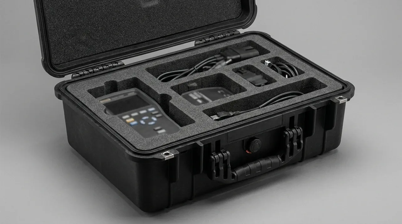
For electrodes with tighter cleanliness requirements, cleanroom-grade packaging materials are worth considering; how cleanliness classes are defined for such materials is covered in cleanroom equipment component protection. Where an electrode has temperature sensitivity, for example certain composite electrodes, the temperature range treatment in wide-temperature range case design is a useful reference.
Liner surface resistance should sit in the static-dissipative band: neither an insulator nor a good conductor. A conductive liner discharges static too quickly, which introduces its own discharge risk. Set the actual resistance range from the customer's ESD control requirements.
Case sealing and cleanliness class
Sealing selection has to satisfy dust exclusion, moisture exclusion and fluid containment at once.
On dust, graphite particles are fine enough that ordinary gaps will not stop them, so the case should meet the dust protection defined in GB/T 4208 or IEC 60529, at IP6X or better. On moisture, sea freight and long storage argue for IP67 at case level with active humidity control inside. On fluid, the dielectric compartment should tolerate a small spill without escape, for example by using a bund of some height in the compartment floor.
It is worth separating two concepts that are often conflated: the case-level ingress rating and the cleanliness class of each internal compartment. A case that reaches IP67 does not thereby deliver clean compartments, because the dust inside originates internally — from the graphite electrodes and from packaging materials — rather than entering from outside. Liner material choice and graphite containment therefore influence compartment cleanliness far more directly than the overall case rating does.
| Requirement | Criterion | Suggested target | How it is achieved |
|---|---|---|---|
| --- | --- | --- | --- |
| Dust exclusion | GB/T 4208 / IEC 60529 | IP6X or better | Gasket plus no through-gaps |
| Moisture exclusion | GB/T 4208 / IEC 60529 | IP67 for sea freight | Gasket at 25–35 percent compression |
| Fluid containment | Internal tolerance | Bund plus absorbent layer | Separate compartment, absorbent material |
| Compartment cleanliness | Internal particle control | Per customer ESD and cleanliness spec | ESD-safe liner plus graphite containment |
| Pressure equalisation | Temperature and pressure change | Breathable waterproof valve | Valve facing away from precision items |
| Static dissipation | Surface resistance | Per ESD control plan | ESD-safe liner and earth terminal |
Sealing construction is discussed in IP67 case sealing structures and interpreting IP ratings on waterproof cases; equalisation valve selection and mounting are covered in the role and selection of case pressure equalisation valves.
Transport testing and cleanliness acceptance
Verification runs on three tracks: transport packaging testing, environmental testing, and cleanliness acceptance. The first two resemble other equipment cases; the third is specific to this case type.
Transport packaging testing centres on the GB/T 4857 series, with vibration and drop as the key tests. Vibration testing should pay attention to electrode displacement inside the cavity, because electrode failures usually come from accumulated small movement rather than a single large shock. After a drop test, re-check the formed surfaces for contact marks.
Environmental testing can cite the high-temperature, low-temperature, humidity and vibration methods of MIL-STD-810H. One point needs stating plainly here: within this industry MIL-STD-810H is referenced purely as a source of environmental test methods. It is not a military certification, and it cannot be presented as evidence that a product holds any military qualification. When agreeing scope with a customer, specify the method number, procedure number, intensity and duration.
Cleanliness acceptance is the distinctive step and is best run in three parts. First, visual inspection after opening, focusing on whether powder has migrated out of the graphite compartment. Second, a wipe test: wipe representative points in the electrical and copper electrode compartments with a lint-free cloth and examine the residue. Third, functional verification, checking boards and terminals for signs of moisture or static damage.
| Acceptance item | Method | Criterion | Action if failed |
|---|---|---|---|
| --- | --- | --- | --- |
| Formed surface condition | Visual plus oblique lighting | No contact marks, no scoring | Scrap or repair assessment |
| Cross-contamination | Wipe electrical and copper compartments | No visible residue on cloth | Clean and replace liner |
| Humidity | Humidity indicator card reading | Within the agreed limit | Replace desiccant and re-check |
| Electrical items | Visual plus insulation resistance spot check | No condensation, resistance acceptable | Dry and retest |
| Restraint condition | Manual check | No movement, no abnormal sound | Re-secure and re-check |
| Indicators | Shock and tilt indicators | Not triggered | If triggered, re-check accuracy |
For batch deliveries, acceptance can be sampled using a single sampling plan to GB/T 2828.1 at general inspection level II, with AQL values separated by defect class. Designing such a plan is described in custom case acceptance and AQL sampling.
Sizing and handling
EDM machines range from compact units with 300 mm travel to large machines beyond 1000 mm, and component masses vary widely. Electrodes run from a few kilograms to over a hundred; spindle head and C axis assemblies commonly sit between 100 and 500 kg; dielectric tanks and power supplies reach 300 to 800 kg.
| Component | Typical mass | Suggested case | Liner focus | Handling |
|---|---|---|---|---|
| --- | --- | --- | --- | --- |
| Small copper electrode | 1–20 kg | Carry compartment case | Formed surface free, datum pocket | One person |
| Large graphite electrode | 20–150 kg | Dedicated sealed case | ESD-safe, powder mat, full enclosure | Two-person lift or trolley |
| Holders and seats | 5–50 kg | Hard compartment case | Locating face sleeves, hard pockets | One person |
| Spindle head assembly | 100–500 kg | Heavy case | Isolation pads, multi-axis locks | Crane or forklift |
| Dielectric pump and valves | 30–200 kg | Mid-size case | Port plugs, absorbent layer | Forklift |
| Power supply and drives | 300–800 kg | Heavy pallet case | Moisture, vibration and ESD protection | Forklift |
Large power supplies and dielectric tanks are bulky with a high centre of gravity, so mark the centre-of-gravity projection on the case side wall and add anti-slip matting under the base. Do not cross-stack; stack identical cases in the same orientation and state the maximum number of layers.
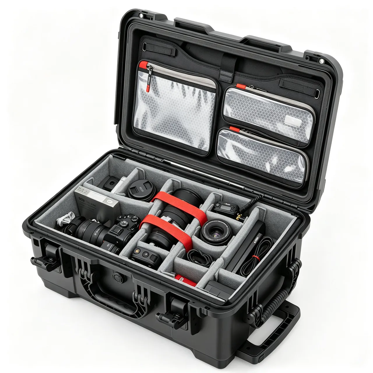
Cases containing electrodes should carry both shock and tilt indicators, with external markings for no-invert, no-roll, keep-dry and ESD-sensitive. Markings must resist oil and heat so that they survive the journey.
On selection, EDM component combinations vary so much that standard case sizes rarely fit directly. The JUNZHIJIA brand is produced by Kexin New Materials (Guangdong) Co., Ltd., which for electrical discharge machining builds compartmented layouts around the electrode schedule and dielectric configuration, covering copper electrode cases, sealed graphite electrode cases, holder compartment cases and moisture-protected electrical cases. Liner anti-static performance, powder collection features and cleanliness treatment can be set to the customer's own control requirements. Goods move through wholesale, distribution and direct worldwide supply, material and inspection documentation is available by contract, and OEM or ODM projects can be produced with customer branding. Where a project needs new tooling, an early cost assessment will show how tooling amortises across the expected batch.
Frequently Asked Questions
Q: Why can a formed surface on an electrode not be cushioned with foam?
A: Because a formed surface is where the discharge takes place and it carries the tightest tolerance on the electrode, so any pressure produces local plastic deformation around the contact point. Copper has low hardness and therefore a low deformation threshold, and even soft foam will leave an impression if it presses continuously under vibration. Once an impression exists the spark gap at that location differs from the design value, and the cavity produced carries a mark in the corresponding position that cannot be corrected by adjusting discharge parameters. Support the electrode on its datum face, mounting shank or process bosses instead, and leave 3 to 5 mm of clear air at the formed surface with no liner material at all. It also helps to standardise electrode design so that every electrode in a family shares the same datum feature and process boss geometry. That single decision lets one cavity design serve many electrodes, and it removes the temptation to solve a fit problem by adding padding where padding must never go.
Q: Can graphite and copper electrodes travel in the same case?
A: Same-cavity packing is not advisable, and separate cases are the preferred solution. Graphite sheds conductive powder under vibration, and that powder migrates through divider gaps and settles on copper electrode formed surfaces or electrical items, causing unstable discharge, abnormal spotting and in the worst case creepage or short circuits. If transport conditions force them into one case, put the graphite electrodes in a sealed box below the copper electrodes so that powder migrates downward, add a sealing membrane between the layers, and move all electrical items out of that case entirely. Graphite must never share a compartment with a control board. Mark the sealed graphite box with ESD-sensitive and graphite-dust warning labels, and make it a fixed container that stays with the electrode rather than a disposable inner box. Reusable containment is what keeps the discipline intact over hundreds of trips, and it also turns powder mat replacement into a scheduled task rather than an emergency.
Q: Can graphite electrodes be cleaned with compressed air?
A: No. Compressed air disperses graphite powder across the whole working area, including the electrical compartment, the copper electrode surfaces and the operator's environment, turning a local problem into a general one. Use a dedicated vacuum with filtration and a soft nozzle, keeping the nozzle off the electrode edges so it cannot knock material loose. For further cleaning, wipe non-formed surfaces lightly with a lint-free cloth and a suitable cleaner; formed surfaces should be vacuumed only. After cleaning, replace the powder mat in the graphite compartment and check the sealed box for powder leakage. Keep a separate vacuum, or at least a separate filter cartridge, for graphite and never use it on electrical compartments afterwards. Cross-use of a vacuum is one of the least obvious ways to defeat an otherwise sound compartment design, because the tool that removed powder from the graphite box will redistribute it everywhere it is used next. Label the graphite vacuum clearly and store it beside the graphite packing station, so it cannot be picked up by mistake for another job.
Q: What locking does a spindle head need before packing?
A: Treat each motion pair according to its type. Fit transport locks on the linear guides so the carriage cannot creep back and forth without preload and mark the raceway. Add a temporary support under the screw so that self-weight cannot bow it and alter preload. Fit an indexing lock pin on the rotary axis and set it at mechanical zero. Protect the taper and face of the electrode clamping end with a cap, because those are precision locating surfaces. Every locking item needs a conspicuous removal tag, and the case exterior should show the lock positions and the removal method so nothing is left in place at commissioning. Shock and tilt indicators are worth fitting on any case containing a spindle head. Record the indicator readings at dispatch on the packing list, and note the axis positions and lock locations alongside them. When a claim or a warranty question arises months later, those two lines of documentation usually settle whether the machine travelled as designed or was packed differently on the return leg.
Q: How completely does the dielectric tank need to be drained?
A: Drain it completely and rinse it once. EDM dielectric is usually mineral-oil based or synthetic, and fluid left in place accumulates and attracts dust to form sludge that is very hard to remove; combined with graphite powder that sludge conducts electricity, which is far worse than either contaminant alone. Work in sequence: drain fully, rinse once with a dedicated cleaner or with the same grade of fresh fluid, then dry thoroughly. Fit gasketed plugs to the drain and return ports, and never substitute tape or cotton waste. Pumps and valve blocks need the same treatment on their ports, with an absorbent layer underneath to keep any small escape local rather than letting it reach the electrode compartments. Before refilling, inspect the tank interior with a light and a mirror rather than by feel, since sludge collects in corners and around baffles where a hand will not reach. If any odour is present, repeat the rinse, because odour usually indicates biological growth in water-based fluid rather than simple oil residue.
Q: Why can compartment cleanliness not be solved by sealing the whole case?
A: Because the dust inside originates internally rather than externally. Graphite electrodes and some packaging materials shed particles by themselves, and a case that reaches IP67 only stops outside dust and water from entering; it does nothing about particles generated inside migrating between compartments. What determines electrical compartment cleanliness is therefore liner material choice and graphite containment rather than the overall ingress rating. Practical measures include specifying liners that neither shed nor attract particles, packing graphite electrodes in a sealed box with a powder mat, installing at least two barriers — a sealing membrane plus a solid divider — between the graphite compartment and any other, and fitting filter pads over cable entries and ventilation openings. Where a compartment carries a cooling fan or an air path, the filter pad becomes a service item and should be listed as one. A clogged pad restricts airflow and raises internal temperature, while a missing pad lets powder straight into the electronics, which costs far more than the pad itself.
Q: What surface resistance should the liner material have?
A: It should sit in the static-dissipative band: not an insulator, and not a good conductor either. An insulating surface accumulates static charge readily, which can discharge when boards or electrodes are handled in a dry environment. A liner that conducts too well dissipates charge too quickly, which introduces its own discharge risk under certain conditions. Set the actual resistance range from the customer's ESD control plan and write it into the purchase specification, because different customers apply different static limits to electrodes and electrical items. Where the customer has no stated requirement, select a conventional static-dissipative material and record actual measurements with a surface resistance meter at acceptance. Set the measurement points in advance — a fixed location on the contact layer, on the pocket wall and on the base — so readings are comparable between cases and between batches. Repeatability matters as much as the absolute value, because drift across a batch is the first sign that a supplier has changed material.
Q: How do you confirm that an electrode is properly restrained after packing?
A: Use a tilt-and-return test. Tilt the packed case slowly to 30 degrees, return it to level, then open it and check the formed surface for contact marks and the electrode for any relative movement. A pass means no marks on the formed surface and no change in position from when it was packed. This test exposes excessive cavity clearance, badly placed clamping points and insufficient support. In addition, push the electrode gently with both hands after packing; it should not move at all. If tapping the case side wall produces visible electrode movement, restraint is inadequate and clamping points or cavity fit need adjusting. Perform the test with the intended packing crew present at least once, since the tap test is easy to describe and easy to perform incorrectly. Tapping hard enough to reveal a restraint problem without denting the case wall is a skill, and a crew that has felt a correct result once will reproduce it consistently afterwards.
Q: What threatens power supplies and board-level components most in transit?
A: Three things: moisture, conductive dust and electrostatic discharge. On moisture, boards and high-voltage components lose insulation resistance in damp conditions, and condensation inside a sea container is the main source; fit adequate desiccant and protect boards accordingly. On conductive dust, graphite powder settling on a board forms a creepage path and can short it, so the electrical compartment must be fully isolated from the electrode compartments and every cable entry and vent needs a filter pad. On static, boards accumulate charge readily during handling in dry conditions, so pack them in ESD bags and require operators to wear grounded wrist straps. Omitting any one of the three tends to appear later as an intermittent fault that is very hard to trace. Write all three into the packing instructions with a signature line rather than relying on general awareness. In practice the moisture step is skipped when desiccant runs out, the dust step when a filter pad is missing, and the static step when a wrist strap is broken — all three failures are trivial to prevent and expensive to discover.
Conclusion and further reading
The design logic for an EDM component case comes down to three ideas: zone, contain and keep cleanable. Zoning means putting electrodes, holders, spindle head, dielectric system and electrical items into compartments that match their cleanliness class and vibration sensitivity. Containing means sealing the graphite electrode, the main contamination source, at source and cutting the migration path with at least two barriers. Keeping cleanable means every surface that can contact graphite must wipe or vacuum clean, with no porous material that swallows powder.
Underneath those three sits the bottom line for electrode protection: zero contact on formed surfaces. Building support on the datum face and process bosses and leaving the formed surface entirely free is a rule that belongs in the design stage; any improvised attempt to pad it with something soft converts the risk into a permanent accuracy loss. When specifying, hand over the electrode schedule, dielectric configuration, cleanliness and static control requirements, transport route and acceptance criteria in one package, and let the manufacturer derive the compartment layout and liner materials from them.
Further reading