

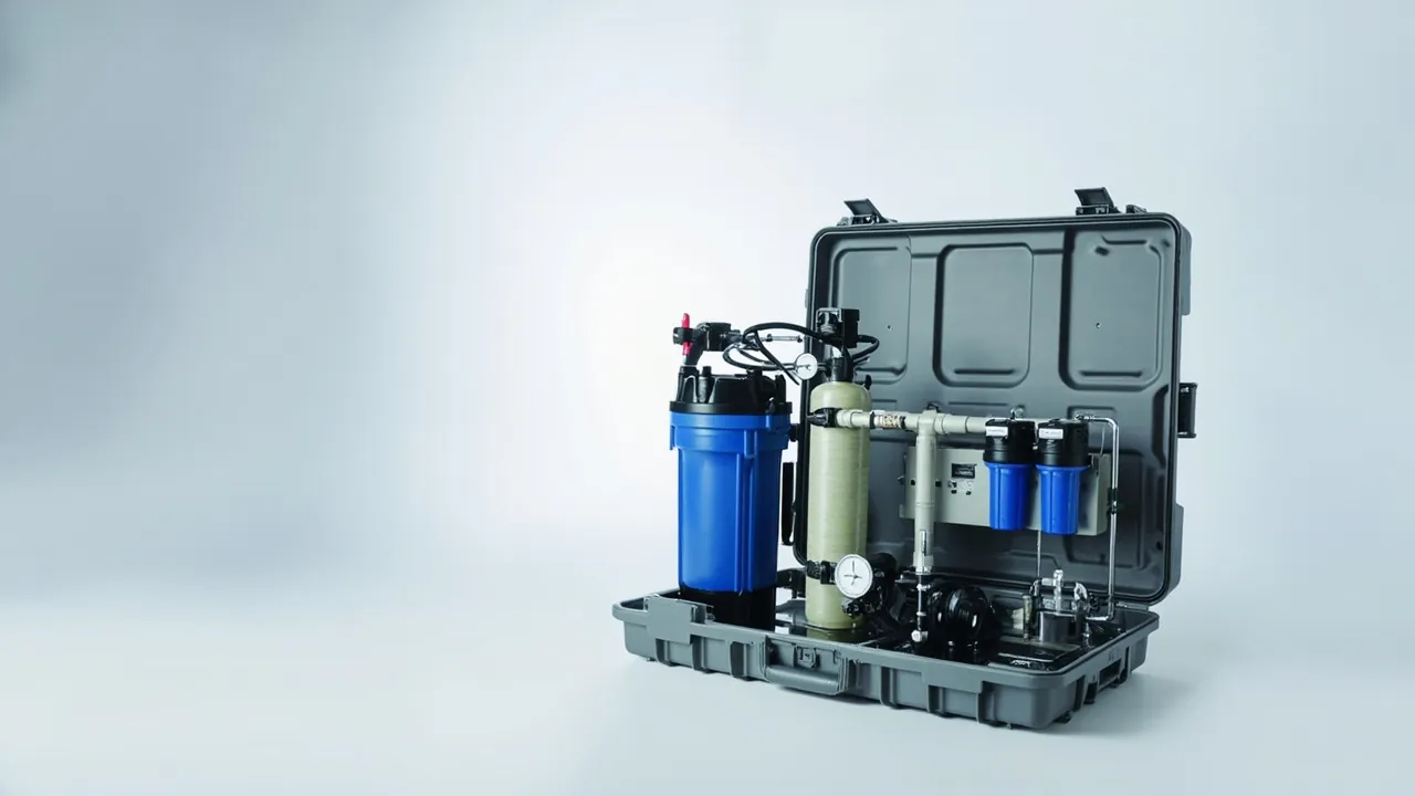
The hard part of protecting water-treatment and environmental equipment in transit is not surviving impact. It is preserving cleanliness, corrosion resistance and instrument calibration. Membrane elements for reverse osmosis, nanofiltration, ultrafiltration and membrane bioreactors normally ship immersed in a preservative solution. If they dry out, freeze or get crushed, the loss of salt rejection and flux may only appear weeks after commissioning. Once particles or axial shock reach a pump, mechanical seals and bearings begin to leak and vibrate. Online instruments such as pH, conductivity, turbidity, residual chlorine and flow meters are measuring devices, and transport vibration or moisture directly shifts their calibration. What these three families share is that the damage is invisible, progressive, and only discovered after the equipment has been installed and put into service.
Water-treatment equipment carries two further constraints. The first is material and cleanliness: RO and ultrafiltration systems use large amounts of 316L stainless steel, PVDF, PVC-U and EPDM, and any residual metal swarf, oil or grit can become a membrane fouling source and can also break down the passive layer on stainless steel. The second is regulatory applicability: equipment and materials used in drinking-water systems normally have to satisfy sanitary safety evaluation requirements in the destination market, and packaging materials must not introduce contamination or odour. This article is written for procurement and packaging engineers at water-treatment contractors, equipment manufacturers, environmental engineering general contractors and export trading firms. All figures are typical industry values or empirical ranges; the governing inputs are the component drawing, the membrane manufacturer's technical manual and the customer's acceptance specification. JUNZHJIA supplies model-specific custom inserts, sealing and corrosion-control configurations, OEM and ODM programmes, and supporting test documentation for water-treatment equipment cases.
Table of Contents
- 1. Why Water-Treatment Equipment Presents a Triple Challenge: Cleanliness, Corrosion and Vibration
- 2. Membrane, Pump and Instrument: Three Failure Modes Compared
- 3. Membrane Element Cases: Moisture Retention, Freeze Protection and End-Face Protection
- 4. Pump and Dosing Equipment Cases: Seal and Wetted-Part Protection
- 5. Valve and Fitting Protection: Seat and Internal Surface Preservation
- 6. Online Instrument Cases: Vibration, Contamination and Calibration Protection
- 7. Component-to-Case Selection Matrix
- 8. Stainless Steel and Coating Protection: Passive Layer and Chloride Risk
- 9. Sealing, Moisture Control and IP Ratings: IEC 60529 and GB/T 4208
- 10. Transport Test Basis: ISTA, GB/T 4857, ASTM D4169 and MIL-STD-810H
- 11. Packing SOP and Pre-Installation Checks
- 12. Sea Export, Returnable Re-Use and OEM/ODM Customisation
- Frequently Asked Questions
- Conclusion and Further Reading
1. Why Water-Treatment Equipment Presents a Triple Challenge: Cleanliness, Corrosion and Vibration
The packaging requirements for water-treatment and environmental equipment split into three separate but interacting chains.
The cleanliness chain. Membrane elements, fine filters, UV chambers and pure-water pipework all demand high cleanliness. Contamination introduced during packing comes from three typical sources: fibre and dust from paper and timber packaging; migratable constituents such as plasticisers and release agents in lining materials; and metal swarf generated by bolts and clamps vibrating inside the case. Once these reach a membrane system they can foul the membrane surface and reduce flux, and the loss often cannot be fully recovered by routine chemical cleaning.
The corrosion chain. Water-treatment equipment uses large quantities of 316L stainless steel, duplex steel and aluminium alloy. The corrosion resistance of stainless steel depends on a dense passive layer, and that layer fails under three conditions: mechanical damage, chloride attack, particularly in stagnant and wet conditions, and iron contamination from direct contact between carbon steel and stainless steel, which produces galvanic corrosion. A 30 to 45 day sea crossing in high humidity and salt fog is a high-risk window for passive layer breakdown.
The vibration chain. Pumps, blowers and agitators are rotating machinery whose bearings, mechanical seals and couplings are sensitive to vibration and axial shock. Online instruments are measuring devices, and vibration changes the geometric relationship inside the sensor, whether electrode, diaphragm or ultrasonic transducer, producing calibration drift. The most troublesome property of instrument damage is that the exterior looks perfect while the reading is already wrong.
One frequently overlooked fact: water-treatment projects usually commission several weeks after installation. Contamination and damage introduced during packing therefore surface only after equipment is installed, pipework connected and the system filled. The cost of remediation at that point is far higher than at the transport stage. Packaging verification for water-treatment equipment should therefore be judged on operating indicators rather than arrival appearance.
These three chains determine the design sequence: define the cleanliness class first, then the corrosion protection level, then the vibration damping level. The order cannot be reversed, because cleanliness requirements directly constrain which lining and packaging materials are permissible.
2. Membrane, Pump and Instrument: Three Failure Modes Compared
| Component | Primary failure mode | Trigger | Typical consequence | Priority countermeasure |
|---|---|---|---|---|
| --- | --- | --- | --- | --- |
| RO or NF membrane element | Drying out, loss of salt rejection | Preservative leakage, package breach, prolonged heat | Reduced flux and rejection | Dedicated moisture cavity plus sealed closure plus puncture-resistant outer case |
| Membrane element | Freeze damage, end-face crushing | Low-temperature transit, stacking pressure, compressed end cap | Membrane sheet rupture, O-ring failure | Insulation layer plus end-cap protection plus surface-contact support |
| UF or MBR module | Hollow fibre breakage, header deformation | Lateral squeeze, unsupported span | Permeate turbidity exceedance, fibre breakage | Fibre bundle cavity plus header support saddle |
| Pump set | Mechanical seal leakage, bearing damage | Axial shock, unrestrained movement | Leakage and abnormal vibration in service | Axial restraint plus rigid foot restraint plus damping pad |
| Pump and dosing unit | Wetted-part contamination, dosing accuracy drift | Ingress of particles, residual metal swarf | Inaccurate dosing, water quality fluctuation | Port capping plus clean lining plus compartment management |
| Valve and fitting | Seat scoring, internal surface corrosion | Hard contact, residual water film, chloride | Internal leakage, pitting perforation | End-face caps plus desiccant plus stainless steel isolation |
| Online instrument | Calibration drift, electrode dehydration | Vibration, moisture, probe drying | Inaccurate readings, frequent calibration | Dedicated compartment plus low-rebound pad plus moisture cap |
| Control cabinet or analyser panel | Solder joint fatigue, insulation loss | Cumulative vibration, condensation | Downtime | Full floating wrap plus desiccant plus humidity indicator |
All eight modes share one property: concealment. Damage originates in transit and appears at commissioning or in operation. The water-treatment industry therefore generally requires a combination of physical testing and functional checks rather than an appearance-only inspection. Failure priority also depends strongly on transport mode: short-haul road transport is dominated by handling shock and stacking pressure, while sea export is dominated by humidity, salt fog and cumulative vibration.
3. Membrane Element Cases: Moisture Retention, Freeze Protection and End-Face Protection
The membrane element is the component in a water-treatment system that cares least about impact and most about its environment. Its protection is therefore about environment maintenance capability, not impact strength.
Moisture retention comes first. RO and NF membrane elements ship immersed in a preservative solution that typically contains sodium bisulphite or a similar agent, and they must remain wet throughout transport and storage. Once the membrane dries, the polyamide active layer undergoes irreversible structural change, salt rejection falls and recovery is not possible. A membrane case must therefore do three things. The primary packaging must itself be sealed, usually the manufacturer's vacuum or sealed bag, with the case providing secondary protection. The case must provide a dedicated moisture cavity so the primary packaging cannot be crushed or punctured. And the case interior must be free of puncture sources such as sharp corners, nails and splinters, which means timber packaging needs surface sealing or an isolating liner.
Freeze and heat protection. Membrane elements carry defined storage temperature ranges, commonly 5 to 35 degrees Celsius, and the manufacturer's technical manual always governs. Below freezing, the preservative solution freezes and damages the membrane structure. Prolonged high temperature accelerates ageing of the membrane material and the O-rings. Northern winter transport and sea crossings across climate zones both need a temperature exposure assessment. Options include insulation layers, temperature-controlled packaging, and verification through temperature indicator labels plus arrival records. General insulation and verification logic for temperature-sensitive shipments is discussed in temperature-controlled transport case design, while the specific limits for membranes always follow the manufacturer's documentation.
End-face and end-cap protection. The end faces of a membrane element, both concentrate and permeate sides, carry the sealing surfaces and connections. Common transit damage includes end-cap deformation, scoring of the O-ring groove, and damage to the centre tube port. The practice is to fit dedicated end-cap protectors on both ends and suspend the element in the insert so the end faces never carry stacking load directly. If stacking is unavoidable, place load blocks at both ends so weight transfers to the case floor through the blocks rather than through the element. Irregularly shaped membrane modules suit custom inserts with dedicated cavities, using the moulding and templating methods described in custom foam insert design guide.
Cleanliness requirements. Membrane inserts should not use materials capable of releasing migratable constituents, and paper fillers should not contact membrane surfaces directly. Where cleanliness is specified, for example for drinking-water or electronics-grade ultrapure water systems, write the lining material and cleanliness control requirements into the technical annex.
4. Pump and Dosing Equipment Cases: Seal and Wetted-Part Protection
The pump set is the heart of a water-treatment system and is often treated too casually in transit, on the assumption that a metal component cannot be damaged. In practice the failure points concentrate in three places: mechanical seal, bearing and flanged connections.
Mechanical seal. A mechanical seal works through contact between a rotating ring and a stationary ring, with face flatness measured in microns. Axial shock in transit displaces or impacts the rings, scoring the sealing faces. Particles entering the seal chamber produce leakage in service. The countermeasure is axial restraint: fit a limit block at the shaft extension so the bearing is not directly loaded by axial acceleration, and secure the shaft so it cannot sag under its own weight.
Bearing. As with fans, bearings are sensitive to axial shock. A drop during handling or a single-point lift transmits through the shaft into the raceway and produces brinelling, which appears later as abnormal noise and early failure. The case must therefore carry clear lifting-point markings, and lifting from the pump body or coupling must be prohibited.
Ports, flanges and wetted parts. Pump suction and discharge connections are easily bumped or contaminated in transit. Cap them with blind plates or dedicated plugs, fit protective covers on flange sealing faces, and avoid direct contact between stainless steel wetted parts and carbon steel components to prevent galvanic corrosion. Dosing equipment, including metering pumps, tanks and pipework, should be drained of residual liquid so leakage does not contaminate other components.
Feet and damping. Pump feet should rest on load blocks with rigid restraint, with a low-rebound damping pad between foot and block to reduce vibration transmission. The load path should run pump, damping pad, load block, case floor, pallet. Using soft foam to carry the weight leads to collapse under prolonged stacking and the pump sinking out of position. The principle is set out in cushion lining and case floor interaction.
Pipework and accessories. Pressure gauges, pressure switches and flow switches are easily damaged and should be removed for separate packing or given dedicated compartments. Couplings, clamps and gaskets should be consolidated into a compartmented box so they cannot move freely, since wandering small parts are a common source of missing-item claims, best managed with a removable divider system.
5. Valve and Fitting Protection: Seat and Internal Surface Preservation
The transport risks for valves and fittings, including butterfly, ball, check and diaphragm valves, flanges, elbows and tees, concentrate at sealing faces, internal surfaces and threads.
Seats and sealing faces. Valve sealing depends on contact between seat and disc, and any scoring creates internal leakage. Keep valves in a partly open or fully open position as appropriate to the valve type, generally avoiding full closure in order to protect the seat, and cover both flange or threaded ends with caps to prevent ingress and impact. Valves should not be stacked on each other or mixed with other metal parts.
Internal surfaces and corrosion. If stainless steel valves and fittings retain moisture internally, pitting can develop in a chloride-bearing environment. Drain and dry the interior, add desiccant, and apply anti-rust treatment to carbon steel items. Note that carbon steel and stainless steel must not contact each other directly, since bolts and gaskets should be isolated to prevent galvanic corrosion in a wet environment.
Lined valves. Rubber-lined and fluoropolymer-lined valves carry a corrosion barrier that is easily damaged. Compression or hard contact causes blistering and delamination, so the lining must be protected from point loading and end-face force should be distributed through guard plates. Avoid over-tight strapping, since a strap tightened across the middle of the body will crush the lining.
Threads and flange faces. Threaded connections should carry plastic protective caps, and flange faces with serrated water lines are permanently leaky once damaged, making protective covers essential. Stack fittings with large diameters below and small diameters above, with separator pads between layers to prevent impression marks.
Case format. Valves and fittings are numerous, varied in size and of moderate unit value, suiting a standard case with a compartmented insert. Compartmentalising by size and labelling by model is the most direct way to reduce site mis-installation and missing items.
6. Online Instrument Cases: Vibration, Contamination and Calibration Protection
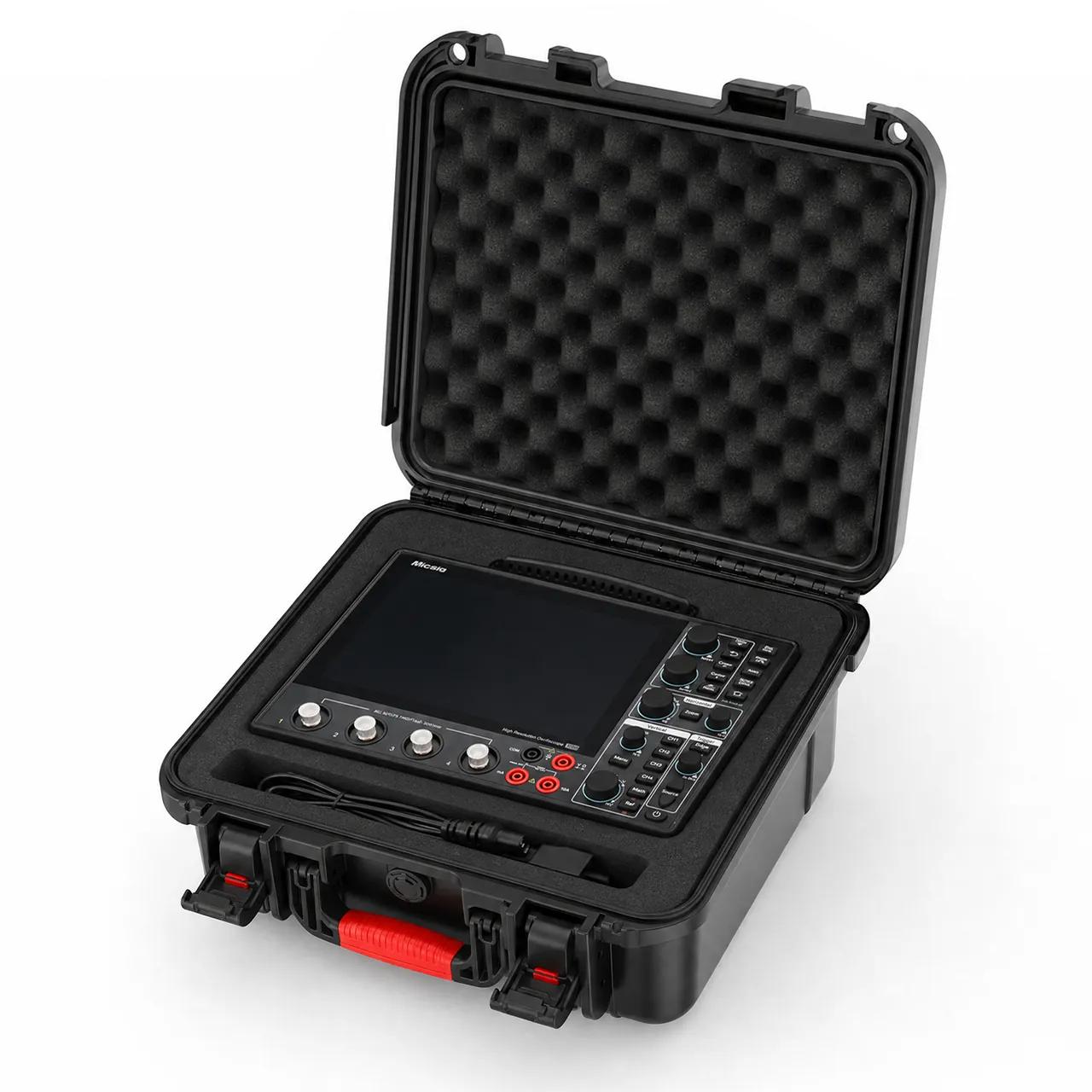
Online instruments, including pH and ORP, conductivity, residual chlorine, turbidity, dissolved oxygen, electromagnetic flow meters and ultrasonic level meters, are measuring devices, and their transport protection logic differs from that of ordinary equipment: an intact appearance does not mean an intact function.
Why instruments suffer from vibration. Different sensor types have different sensitive structures. A pH glass electrode has an extremely thin glass bulb that breaks under impact. A conductivity electrode's constant depends on the geometry and spacing of its plates, which vibration can shift. Turbidity and dissolved oxygen sensors have optical windows and membranes that are highly displacement-sensitive. An electromagnetic flow meter's liner changes internal diameter and electrode position if compressed. An ultrasonic level meter's transducer is a piezoelectric element whose resonance characteristics can change after impact. These changes typically appear as calibration drift rather than outright failure.
Damping design. Instrument damping should follow a low-rebound, low-amplitude strategy: use low-rebound EVA or PU for a full floating wrap, and avoid high-rebound materials, which bounce vibration back into the instrument. The instrument must not touch any rigid surface on any side, and the probe in particular needs its own clearance. The electronic head and transmitter should follow the anti-vibration and moisture principles in instrument case selection guide, and where precision electronic boards are involved, ESD shielding options may also be considered.
Probe protection and hydration. The sensing membrane of a pH or dissolved oxygen electrode deactivates if it dries, so a moisture retention cap containing protective solution or a damp sponge should be fitted for transport. The liquid in the cap must not leak onto other components, so the compartment layout must give the cap its own position with leak containment. Glass electrodes tolerate neither impact nor compression and should be compartmentalised separately with soft padding.
Cleanliness and contamination. Optical windows and electrode surfaces must not contact oil, dust or migratable contaminants. Lining materials should have controlled cleanliness, and the case interior should avoid shedding fillers. If instruments ship in the same case as membrane elements, strict zoning is required so instrument packaging cannot contaminate the membranes.
Cables and accessories. Instrument cables, calibration solutions and spares should be compartmentalised. Calibration solutions are chemical reagents, and if they must accompany the shipment, confirm that their packaging meets transport requirements, with leak containment and labelling. Whether such goods are classified as dangerous goods must be determined by a qualified body; this article draws no conclusion on that point.
Arrival verification. Three checks are recommended on arrival: exterior and probe integrity; whether the moisture cap still contains liquid, which indicates whether dehydration occurred; and a quick check against a standard solution to detect drift. All three can be completed before installation at low cost and with clear results.
7. Component-to-Case Selection Matrix
| Component | Typical weight | Insert scheme | Case format | Sealing guidance | Critical constraints |
|---|---|---|---|---|---|
| --- | --- | --- | --- | --- | --- |
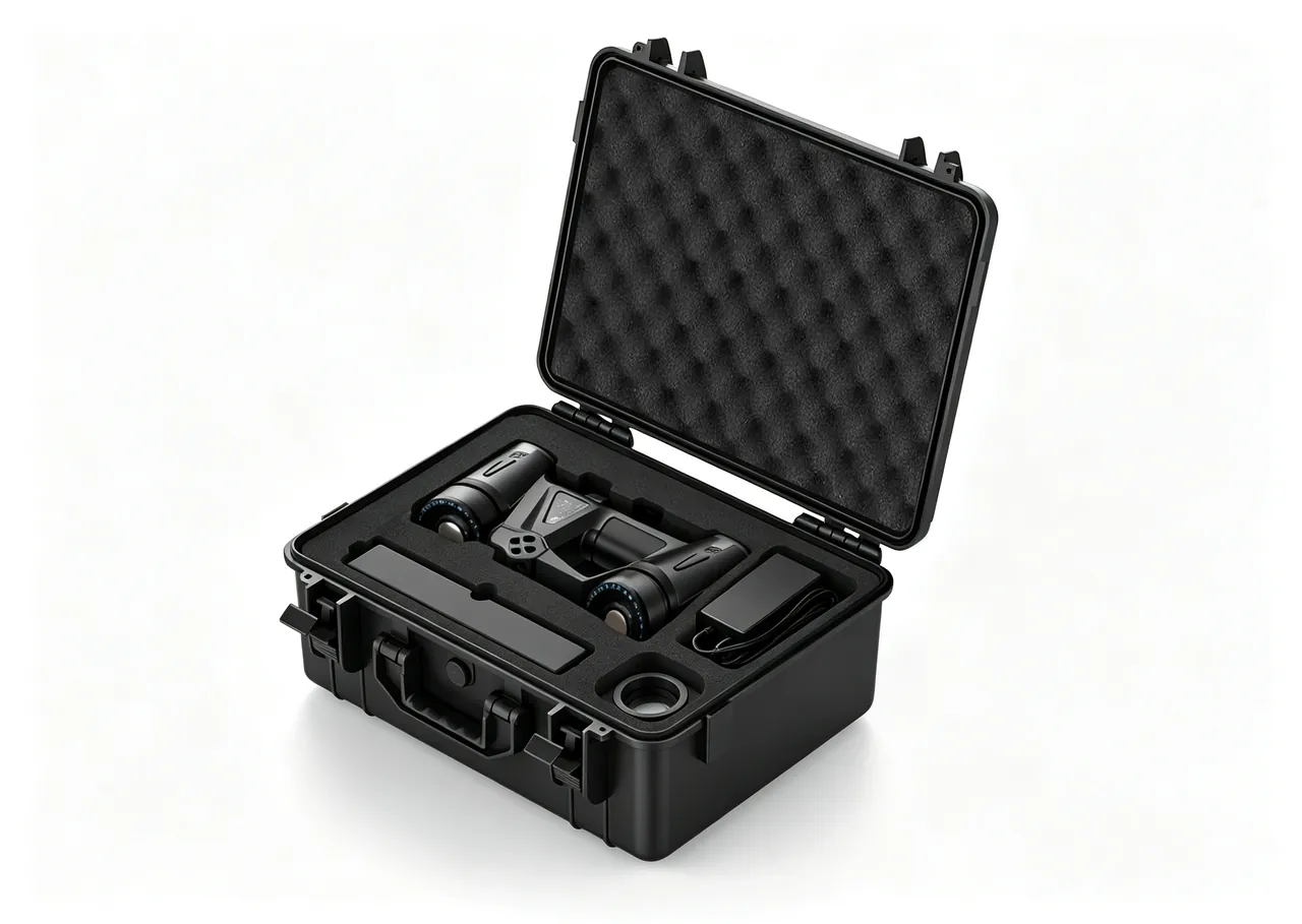
| RO or NF membrane element (4040/8040) | 15-20 kg each | Dedicated moisture cavity plus end-cap protectors | Long reinforced case | IP65 | Moisture, freeze protection, puncture resistance |
| UF or MBR module | 20-120 kg | Fibre bundle cavity plus header saddle | Medium reinforced case | IP65 | Lateral squeeze, unsupported span |
| Centrifugal or multistage pump | 20-300 kg | Damping pad, load block and axial restraint | Heavy frame or pallet case | IP65 | Mechanical seal, lifting-point marking |
| Metering pump or dosing unit | 10-60 kg | Compartmented insert with separate tank cavity | Medium case | IP65/IP67 | Drain residual liquid, leak containment |
| Valve (butterfly or ball) | 5-80 kg | End-face caps plus compartmented insert | Standard case with dividers | IP65 | Seat protection, no stacking |
| Online instrument (pH, conductivity, turbidity) | 1-15 kg | Low-rebound floating wrap plus dedicated compartment | Carrying or medium case | IP67 | Moisture cap, anti-vibration, anti-contamination |
| Electromagnetic flow meter | 15-70 kg | Liner protection plus support at both ends | Long reinforced case | IP65/IP67 | Liner compression, electrode protection |
| Control cabinet | 40-200 kg | Low-rebound EVA full floating wrap | Upright case with castors | IP65 plus desiccant | Vibration, moisture, ESD |
Two empirical rules apply. Where a component contains glass, ceramic or optical elements, assume a drop risk exists, so the case must survive the specified drop condition while attenuating shock to a level that will not destroy the fragile element. Where a component is destined for a drinking-water or ultrapure-water system, treat the lining material as a wetted-material candidate, not as ordinary packaging.
8. Stainless Steel and Coating Protection: Passive Layer and Chloride Risk
Corrosion protection for water-treatment equipment is fundamentally protection of surface condition. Stainless steel resists corrosion because of a dense passive layer based mainly on chromium oxide, and once that layer is damaged and cannot self-repair, corrosion develops from the damage site.
Three main causes of passive layer failure.
- Mechanical damage: scoring, impact and hard contact. Carbon steel tools contacting a stainless surface embed iron ions and create a local corrosion cell. Stainless parts should therefore be handled with stainless or non-metallic tools and slings, and grinding on finished surfaces is prohibited.
- Chloride attack: in wet and stagnant conditions, chlorides cause pitting and crevice corrosion. Sea-fog exposure, coastal warehousing and residual moisture inside a case are all high-risk factors, so the case needs desiccant and a humidity indicator card.
- Cross-contamination: direct contact between carbon steel and stainless steel produces galvanic corrosion. Packaging design must isolate the two material groups using plastic separator pads or non-metallic clamps, and fasteners and gaskets need material isolation.
Practical measures at the packing stage.
- Where a protective film is applied to stainless surfaces, choose a low-residue adhesive and remove it within the specified period, since long-dwelling film causes hard-to-remove residue and under-film corrosion.
- Never clean stainless surfaces with chloride-bearing cleaners, including sodium hypochlorite products.
- Packaging materials must not contain migratable chlorine or sulphur constituents.
- Untreated timber fillers must not contact stainless surfaces directly, since acidic constituents and moisture in the timber accelerate corrosion.
- Use dedicated protective caps on flange faces and threads rather than simply wrapping tape.
Coated and carbon steel parts. Coatings on carbon steel frames and bases are easily scored in transit, and a score becomes a rust initiation point that spreads outward. Use conforming padding at contact faces and corner protectors at high-wear points. For sea export, assess the salt-fog resistance of the coating system in advance.
Sanitary and wetted-material requirements. Components and materials used in drinking-water systems normally have to satisfy sanitary safety evaluation requirements in the destination market, and packaging materials must not introduce contamination or odour. The specific applicable standards and evaluation requirements depend on local regulations, customer technical requirements and the product's sanitary approval documentation; this article draws no compliance conclusion. Where equipment serves the food and beverage industry, material requirements may follow food-contact evaluation logic, but applicability must be confirmed by the customer against the governing regulations.
9. Sealing, Moisture Control and IP Ratings: IEC 60529 and GB/T 4208
Water-treatment equipment faces widely varying transport environments. Domestic short-haul overland freight is relatively dry, while sea export brings high humidity, salt fog and temperature swing. The goal is a match to the environment, not maximum tightness.
What the IP code means. The IP code defined in IEC 60529 uses two digits, the first for solids protection from 0 to 6 and the second for water protection from 0 to 9K. The equivalent Chinese standard is GB/T 4208. Typical configurations for water-treatment cases are as follows.
- IP54: limited dust protection and splash resistance for short domestic routes with covered transport.
- IP65: dust tight and water-jet resistant for most components on domestic and near-sea routes.
- IP67: dust tight with short-term immersion tolerance, typically 1 m for 30 minutes, for sea freight, open-air storage and high-humidity regions.
- IP68: continuous immersion, needed only in extreme scenarios such as vessel decks and long-term outdoor storage.
Trade-offs between these levels are examined in IP67 protective case design essentials and the practical meaning of IP water ratings.
Key reminder: an IP rating verifies that external water does not enter. It does not guarantee that condensation will not form inside. A sealed case cannot easily expel internal moisture across a day-night temperature cycle, which is bad for membrane elements, instruments and control cabinets alike. Sealing, desiccant and a humidity indicator card should therefore be treated as a standard combination, with a pressure equalisation valve added on routes with large temperature swings so the case can equalise pressure without drawing in moisture.
Seals and wear parts. Gasket materials are commonly silicone, EPDM and foamed TPE. Silicone offers the best temperature and weathering resistance at higher cost. EPDM balances ageing resistance and weatherability for outdoor duty. Foamed TPE has low compression set and suits cases that open and close frequently. Gasket cross-section must match the case groove, as detailed in hinge, latch and seal selection. Seals are wear items and need a spare parts list with replacement criteria.
Desiccant selection and quantity. Desiccant quantity should be calculated from free internal volume, the hygroscopicity of packaging materials, transit duration and target humidity, not from a rule of thumb about how many sachets to add. A 30 to 45 day sea crossing requires substantially more than a short domestic route, and a humidity indicator card should be included for arrival assessment. Where the case contains large amounts of paper or timber, their own moisture uptake consumes desiccant capacity and must be included in the calculation.
10. Transport Test Basis: ISTA, GB/T 4857, ASTM D4169 and MIL-STD-810H
"Our cases are strong" is not an acceptable statement. An acceptable statement is that the case passed a specific test sequence under a named standard.
The ISTA series. Procedures from the International Safe Transit Association are graded by package format and weight. Medium and large equipment and components commonly reference ISTA 3E for unitised loads or ISTA 3B for less-than-truckload distribution, while single packages suit ISTA 2A or 2B. The value of ISTA lies in sequencing: conditioning, then shock or drop, then vibration, then re-inspection. See ISTA transport testing procedures.
The GB/T 4857 series. These Chinese standards cover basic test methods for transport packages including vibration, shock, stacking and drop, and are widely referenced in domestic tenders and acceptance documents. See GB/T 4857 transport packaging.
ASTM D4169. This standard assigns test intensity by distribution cycle and is widely used for packaging validation targeting the North American market. See ASTM D4169 distribution cycle testing.
MIL-STD-810H. Its environmental test methods covering vibration, shock, temperature and humidity, and salt fog are frequently cited. This must be stated clearly: MIL-STD-810H is used here as a source of environmental test methodology and does not imply that any product has obtained military certification. See MIL-STD-810H environmental test compliance.
| Test type | Common standard | Example parameters | Relevance to water-treatment equipment |
|---|---|---|---|
| --- | --- | --- | --- |
| Random vibration | ISTA 3E, ASTM D4169 | Power spectral density, duration | Verifies instrument calibration stability and pump seals |
| Shock and drop | GB/T 4857, ISTA | Drop height, peak acceleration | Verifies membrane end faces and glass electrodes |
| Stacking | GB/T 4857.3 | Load, duration, temperature and humidity | Verifies membrane end-face crush resistance and case strength |
| Temperature and humidity cycling | MIL-STD-810H Method 507 | Temperature range, cycle count | Verifies sealing, condensation and preservative stability |
| Low temperature | MIL-STD-810H Method 502 | Low temperature value, duration | Verifies freeze protection for membranes and instruments |
| Salt fog | ISO 9227, ASTM B117 | Concentration, duration | Verifies stainless steel passive layer and coatings |
On functional checks. Transport verification for water-treatment equipment must include functional items, which is the industry's distinguishing requirement. After vibration and temperature-humidity testing, check whether membrane primary packaging is still sealed, whether preservative solution is present, and whether there are signs of freezing; check instruments for drift against a standard solution; check pumps for free rotation and leakage; and check valves for correct operation. Acceptance criteria should be functional first and cosmetic second, otherwise hidden damage cannot be intercepted. Where membrane performance evaluation is required, industry test method standards for membrane performance can be used as a source of test thinking, with applicability determined against the membrane manufacturer's technical manual.
On test documentation. Write the test item, standard number, sample quantity, functional checks, acceptance criteria and report issuer into the technical annex of the contract, along with responsibility for rectification and retesting if the result fails.
11. Packing SOP and Pre-Installation Checks
- Verify and clean. Confirm model, quantity and accessory list. Remove oil, metal swarf and residual liquid, focusing on membrane end faces, instrument probes and stainless surfaces.
- Pre-treat for protection. Confirm membrane primary packaging is sealed and holds sufficient preservative solution and fit end-cap protectors. Fit moisture retention caps to instruments with leak containment. Cap pump ports and cover flange faces. Keep stainless parts away from direct carbon steel contact.
- Pre-fit the lining. Place load blocks, damping layers, compartments and limit blocks according to position markings. The first article should be trial-fitted and recorded.
- Position the component. Lower into the design attitude without dragging or single-point lifting. Confirm no contact with any rigid surface, no load on membrane end faces and no compression of instrument probes.
- Restrain and locate. Install the top locating pressure block. Straps are auxiliary only and must use corner protectors. Confirm no perceptible movement when pushed by hand, with an empirical limit of 2 mm displacement.
- Accessories and documents. Place bolts, clamps, gaskets and special tools in the compartmented box. Put documents in a pouch fixed to the inside of the lid.
- Seal and dry. Add desiccant sized from internal volume and transit duration, plus a humidity indicator card. Check the gasket. Close the latches and confirm uniform loading around the perimeter.
- Mark and record. Apply centre-of-gravity, lifting, rain-protection, this-way-up, temperature-sensitive and cleanliness labels. Photograph the packed case and archive the images.
Field experience: a three-point verification works well for water-treatment equipment. Record functional baselines before packing, including an instrument check against standard solution and confirmation of membrane primary packaging integrity; photograph the packed case; then repeat the same measurements on arrival. Three data sets form a complete responsibility chain that distinguishes incoming-material issues, transport issues and installation issues.
Pre-installation checklist. On arrival and before installation, complete the following checks: case exterior and seal integrity; desiccant condition and humidity indicator colour; whether membrane primary packaging is still sealed, with sufficient preservative solution and no signs of freezing; whether instrument moisture caps still contain liquid; scoring on probes, optical windows and flange faces; whether pumps rotate freely by hand without leakage; and whether stainless surfaces show rust spots or iron contamination. If an anomaly appears, photograph it on the spot, preserve the original packaging and do not move the component a second time.
People and tools. Use stainless or non-metallic slings for stainless parts. Never grip a membrane element by its end face or centre tube. Carry instruments with both hands supporting the base, never by the cable or probe. Never clean stainless surfaces with chloride-bearing cleaners.
12. Sea Export, Returnable Re-Use and OEM/ODM Customisation
Five key variables in sea export. First, transit lasts 30 to 45 days, so desiccant quantity must be calculated from free internal volume and duration, including the hygroscopicity of paper and timber packaging. Second, the day-night temperature swing inside a container drives condensation, so a pressure equalisation valve is advisable. Third, deck carriage and open-air storage expose metal hinges, latches, handles and fasteners to salt fog, requiring a higher corrosion class, with particular attention to galvanic couples where stainless and carbon steel meet. Fourth, stacking layers at sea are usually higher, so compressive strength must be calculated for the worst-case stack, and membrane elements especially must not carry end-face load. Fifth, export wooden packaging must meet ISPM 15 fumigation or heat treatment requirements; a plastic case avoids this issue but must still satisfy the destination market's environmental and recyclability requirements for plastic packaging. Finally, sea freight usually connects to local truck delivery, and that last short leg often produces the most severe handling shock.
Low and high temperature routes. Where the route may pass through cold regions or prolonged high temperature, carry out a dedicated temperature exposure assessment for membranes and instruments. A practical verification method is to ship a temperature data logger inside the case and read the temperature curve on arrival, producing a traceable record that is very effective for responsibility determination.
Returnable re-use and criteria. Water-treatment projects commonly recycle packaging after installation. Check five items before reuse: shell cracks or deformation, especially floor and corners; gasket hardening, cracking or permanent set; latch and hinge ability to close and carry load; lining collapse, fracture or missing compartments; and castor and handle wear. Replace any failed item before reuse. One industry-specific warning applies here: a case previously used to transport chemical reagents or residual liquids must be confirmed free of contamination and odour before being used for membrane elements or instruments, and the lining should be replaced if there is any doubt. Implementing a purpose-dedicated policy, so that cases used for chemicals are never reused for membranes, instruments or wetted components, is the safest approach.
OEM/ODM points. Water-treatment cases are a high-variation, fragmented-specification category, so the procurement strategy should be built around standardised cases with customised linings: cover most components with three to five standard case sizes, then adapt specific models through custom linings, amortising tooling cost. See custom case mould cost analysis.
Five dimensions for supplier evaluation. Engineering capability, meaning the ability to issue an insert proposal from 3D data or a physical impression and run a trial fit. Materials and process, covering foam density batch consistency, gasket cross-section and hardness, and cleanliness control capability. Test capability, covering vibration, drop, stacking, water ingress and temperature-humidity records. Delivery and capacity, including peak-season flexibility. Quality system, including inspection rules and non-conforming material handling, using the sampling practice described in custom case acceptance and AQL.
Enquiry checklist. A practical enquiry should include the component model and specification, weight and centre of gravity, membrane preservative and temperature requirements, transport mode and route, number of re-use cycles, storage environment, target IP rating, cleanliness requirements, test requirements, marking requirements, annual volume and delivery cadence. General guidance on evaluating factories is available in how to choose a protective case OEM factory.
JUNZHJIA normally works in the following sequence for water-treatment and environmental equipment cases: accept 3D data or take a physical impression, issue a zoned insert proposal with sealing and corrosion-control recommendations, confirm the first article by trial fitting, then move to volume production with batch inspection and supporting test documentation. For long-term customers, a component archive is maintained so repeat orders reuse the approved design.
Frequently Asked Questions
Q: What is the most overlooked risk when transporting reverse osmosis membrane elements?
A: The most overlooked risks are environmental rather than mechanical: dehydration and freezing. The polyamide active layer of a membrane element is stable while wet, and once it dries it undergoes irreversible structural change, showing up as reduced salt rejection and flux that cleaning cannot restore. Common causes include poor primary packaging seals, puncture of the primary packaging by sharp objects inside the case, with nail heads and splinters on untreated timber surfaces being a classic source, and compression damage from stacking. Freezing matters just as much, since the preservative solution expanding as it freezes damages the membrane structure, so the minimum temperature on the route must be assessed and insulation layers plus a temperature data logger used where needed. In the contract, state clearly that the membrane manufacturer warrants primary packaging integrity, while the case provides secondary protection against puncture, stacking pressure, temperature excursion and moisture. On arrival, make the seal condition of the primary packaging and the presence of preservative solution mandatory check items.
Q: Stainless steel parts show rust spots after sea freight. What usually causes this?
A: In most cases the stainless material itself is not at fault; the passive layer has been disrupted or the surface contaminated. Three typical causes apply. First, mechanical damage where carbon steel tools and slings contact the stainless surface and embed iron ions, creating a local corrosion cell. Second, direct contact between carbon steel and stainless steel components, producing galvanic corrosion in a wet environment. Third, chloride attack, where sea fog and residual moisture inside the case combine at crevices and pooled areas to form pits. Two further causes are common: cleaning with chloride-bearing agents, with sodium hypochlorite products being the worst offenders, and long-dwelling protective film causing under-film corrosion. Countermeasures include using stainless or non-metallic slings and fixtures, fitting non-metallic separator pads between carbon and stainless steel, placing sufficient desiccant with a humidity indicator card, banning chloride cleaners, specifying low-residue protective film removed within the stated period, and cleaning and inspecting passivation condition promptly on arrival.
Q: An online instrument reads differently after transit. How do I tell whether it is a transport or an installation issue?
A: Build a three-point baseline: measure the same standard solution before packing, on arrival, and after installation, creating three data sets. The pre-packing reading establishes the factory condition. If the arrival reading, taken at the same temperature with the same standard solution, has already shifted, the cause is most likely transport-related vibration, moisture, or probe dehydration. If arrival is normal but the post-installation reading drifts, the cause is more likely installation-related, such as wiring, grounding, flow disturbance or process conditions. Also check three physical clues: whether the moisture cap still contains liquid, since a dry cap indicates possible probe dehydration and pH glass and dissolved oxygen membranes are especially sensitive; whether optical windows and electrode surfaces show scoring or contamination; and whether transmitter terminals show moisture. Specify an arrival functional verification clause and acceptance criteria in the technical annex, and standardise the method and record form so that both parties agree on how the judgement is made before any dispute arises.
Q: Why can a membrane case not simply be a wooden crate with foam?
A: A wooden crate with ordinary foam may be adequate for load bearing, but it creates three specific problems in water-treatment applications. First, puncture risk: timber surfaces can carry nail heads, splinters and rough edges that pierce membrane primary packaging under vibration, causing preservative leakage and membrane dehydration, which is the most direct failure path. Second, moisture uptake and cleanliness: timber absorbs moisture and becomes a humidity reservoir, consuming desiccant capacity while potentially releasing acidic substances and fibre fragments that contaminate membrane surfaces and instrument probes. Third, contamination migration: timber and some low-cost foams can release migratable constituents, which is undesirable for high-cleanliness membrane systems. A better approach is a plastic or composite case body with cleanliness-controlled lining materials and a dedicated moisture cavity, isolating the timber pallet from the internal cavity so timber never contacts membranes or instruments. Where a wooden crate is genuinely required, for example for an oversized module, seal the inner surfaces and add an isolating liner.
Q: Besides conventional vibration and drop tests, what else should water-treatment packaging validation include?
A: Add three special categories to the conventional physical tests of random vibration, shock and drop, stacking, temperature-humidity cycling, salt fog and water ingress. First, low-temperature testing to verify freeze protection for membranes and instruments, using the approach of MIL-STD-810H Method 502, noting that referencing its methods does not imply military certification. Second, functional checks, which are the industry's distinguishing requirement: after vibration and temperature-humidity testing, verify membrane primary packaging sealing and preservative condition, instrument calibration drift, pump rotation and leakage, and valve operation, with acceptance judged on functional criteria first. Third, cleanliness and contamination control validation, which for high-cleanliness applications can include an assessment of migratable constituents in lining materials and confirmation that the case contains no metal swarf or fibre sources. It is also worth shipping a temperature data logger on any route with significant temperature swing, so the actual exposure curve becomes part of the record. Write these items, standard numbers, acceptance criteria and the report issuer into the contract technical annex in advance.
Q: A pump leaks from its mechanical seal after transit. What are the common causes?
A: Four causes dominate, and most point to axial restraint or cleanliness. First, axial shock: a drop during handling or a single-point lift transmits through the shaft into the sealing faces of the rotating and stationary rings, causing scoring or relative displacement that leaks in service. Second, poor shaft restraint: the shaft sags under its own weight or oscillates during transport, causing repeated micro-movement and wear at the sealing faces. Third, particles entering the seal chamber, where insufficient cleanliness control inside the case allows metal swarf or grit onto the sealing faces, producing abrasive wear in operation. Fourth, partial disassembly, where a coupling or guard is removed for shipping and the seal faces are left exposed to a dusty environment when repacked. Countermeasures are to provide an axial limit block and shaft support inside the case, mark lifting points on the case exterior and prohibit lifting from the pump body or coupling, cap pump ports, avoid shedding fillers inside the case, and rotate the pump by hand to confirm free movement before any powered test run.
Q: How should I choose the IP rating for a water-treatment case, and is higher always better?
A: No. Select against actual exposure. For domestic road transport with covered storage, IP54 to IP65 is usually sufficient, while sea freight, open-air storage, rainy or high-salt-fog regions call for IP67. Two points deserve emphasis. First, IP67 only guarantees that external water does not enter; it does not prevent condensation, and the day-night temperature swing on a sea crossing produces visible internal condensation that is bad for membranes, instruments and control cabinets alike, making desiccant and a humidity indicator card close to mandatory. Second, a higher sealing level means a greater pressure differential across temperature changes, which makes the case harder to open and can distort the gasket, in which case a pressure equalisation valve is more effective than a higher IP number. One water-treatment-specific consideration applies as well: where the case contains large amounts of paper or timber, their moisture uptake consumes desiccant capacity significantly, and in that situation increasing desiccant quantity is more practical than raising the IP rating. Where a tender document specifies an IP rating, that document governs and the supplier should provide matching test records.
Q: Can a used transport case still be reused for membrane elements and instruments?
A: Yes, but explicit re-use criteria are needed, along with attention to one industry-specific risk: previous contents. Begin with the case itself. Check the floor and corners for cracks and deformation; check the gasket for hardening, cracking, debonding or permanent set; verify that latches and hinges close reliably and carry load; check the lining for collapse, fracture, missing compartments or dusting; and review castor and handle wear. Replace any failed item before reuse. Then consider the water-treatment-specific risk. A case previously used for chemical reagents, chlorinated disinfectants or saline solutions may have lining and gaskets that adsorbed residual constituents even after visible cleaning, and those constituents can slowly release and contaminate membrane surfaces or corrode stainless steel. A purpose-dedicated policy is recommended, so cases used for chemicals are never reused for membranes, instruments or wetted components. Where reuse is unavoidable, replace all linings and gaskets and confirm the case has no odour or residue. Maintain a log of case number, cycle count, previous contents and inspection records.
Q: We stock many specifications of membrane elements, valves and instruments. How can packaging cost be controlled?
A: The core approach remains standardised cases, customised linings, purpose-dedicated tracks and numbered management. First, group cases into three to five standard sizes by volume and load capacity to cover most specifications, spreading tooling cost across many models. Second, customise linings per component, but since the case cavity is standard the linings remain interchangeable, reducing inventory and changeover cost. Third, operate purpose-dedicated tracks: membranes and instruments form a clean track, valves and fittings a general track, and chemicals and reagents a dedicated track, with no crossover between case and lining sets in order to prevent contamination migration. Fourth, build a packaging record for each specification containing 3D data, lining drawing number, cleanliness requirements, packing photographs and test records, so a repeat order reuses the approved design. Fifth, include cycle count in the cost model, comparing single-use packaging on unit price against returnable packaging on unit price divided by cycle count plus maintenance cost, and include replacement cost for wear items such as gaskets, desiccant and protective caps. For very low-volume prototype items, use a standard case with a temporary lining as an interim measure and tool a formal lining once the specification stabilises.
Conclusion and Further Reading
Protecting water-treatment and environmental equipment in transit is fundamentally about protecting what cannot be seen: the active layer of a membrane, the passive layer of stainless steel, and the calibration baseline of an instrument. None of the three gives a clear damage signal at unpacking, yet all three surface later as falling salt rejection, pitting perforation or reading drift once the system is running. Packaging design for this equipment must therefore proceed along three parallel chains in sequence: define the cleanliness class, which decides which materials are permissible; define the corrosion protection level, which decides isolation and drying provisions; and define the damping level, which decides the insert structure.
The implementation path compresses into four steps: define component characteristics and transport route, establish cleanliness and corrosion boundaries, design case, lining and sealing by zone, then close the loop with transport testing plus functional checks. Only then is the risk of intact arrival and abnormal operation reduced to a minimum. Where a zoned insert proposal with sealing and corrosion-control recommendations is needed for a specific model, provide the 3D data, component materials and transport mode to JUNZHJIA, which will issue drawings against the model and arrange first-article trial fitting.
Further Reading