

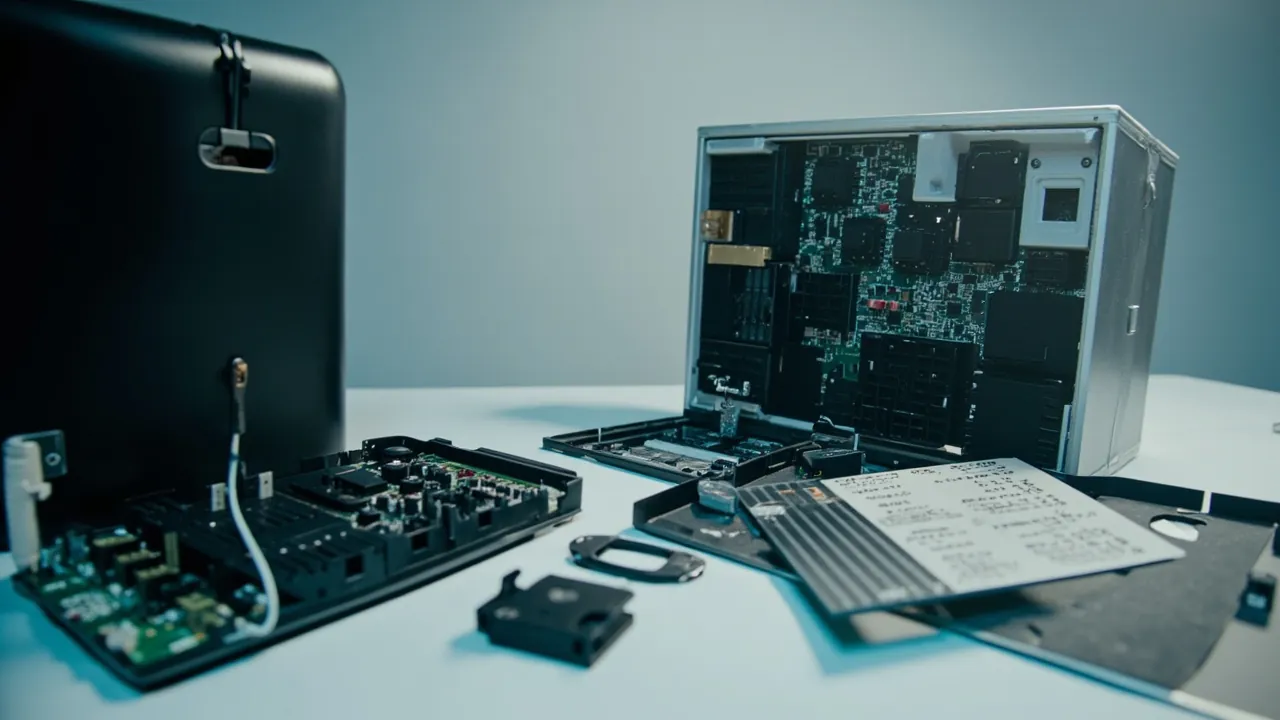
A PCB transport case has to resolve four mutually constraining problems at the same time: preventing electrostatic discharge from destroying components, stopping boards from absorbing moisture that causes popcorning during reflow, avoiding scratches on board surfaces and edges during handling, and suppressing warp in thin boards under stacking load. The short answer: a compliant PCB transport case is not a plastic crate. It is a handling system built from static-dissipative materials, adjustable dividers or moulded inserts, a moisture barrier and stacking stops. Acceptance should cover the packaging material requirements of ANSI/ESD S20.20 and ANSI/ESD S541, the printed board handling and storage guidance in IPC-1601, the moisture-sensitive device handling requirements of IPC/JEDEC J-STD-033, the ingress protection classes of IEC 60529 / GB/T 4208, and GB/T 4857 transport test methods.
PCBs are among the most frequently moved materials in electronics manufacturing: from the board shop to the SMT line, from placement to through-hole assembly, from test to final assembly, and from repair back to rework. In one complete manufacturing cycle, the same batch may be loaded and unloaded a dozen times or more. The bare board itself is not fragile, but the components, plating, solder mask, gold fingers and fine traces on it are extremely sensitive to static, moisture and mechanical friction. For high-density interconnect (HDI) boards, flexible printed circuits (FPC) and rigid-flex boards, warp and delamination risk is higher still. This article is written for SMT process engineers, electronics manufacturing quality engineers and warehouse logistics procurement teams. It provides material selection, structural design, moisture control, standards references and an acceptance checklist, so that "ESD safe and moisture proof" becomes a verifiable hardware specification rather than a slogan.
Table of Contents
- 1. How PCBs Fail in Transit: ESD, Moisture, Scratches and Warp
- 2. The ESD Protection System: From Standards Framework to Practical Metrics
- 3. Material Surface Resistance and Static-Dissipative Insert Selection
- 4. Moisture Control: How PCBs Absorb Water and Why Popcorning Happens
- 5. Moisture Barrier Packaging and Desiccant Configuration
- 6. Warp and Edge Damage: Support, Stacking and Board Spacing
- 7. Inserts and Dividers: Achieving Zero Inter-Board Friction
- 8. Case Structure: Stacking, Handling and Automation Compatibility
- 9. Sealing Levels and IP Protection Selection
- 10. Cleanliness and Contamination Control: Ionic Residue and Particles
- 11. Standards Reference: The IPC Family, J-STD-033 and Transport Testing
- 12. Transport Verification: Applying ISTA and GB/T 4857
- 13. Pre-Shipment Inspection and Acceptance Points
- 14. Case Cleaning, Maintenance and Life Management
- 15. Common Misconceptions and Engineering Recommendations
- Frequently Asked Questions
- Conclusion and Further Reading
1. How PCBs Fail in Transit: ESD, Moisture, Scratches and Warp
PCB failures in logistics fall into four categories. Understanding the mechanisms is what makes the right solution selectable.
Category one: electrostatic discharge. MOS devices, CMOS chips, thin-film resistors and some sensors on the board are extremely static sensitive. Walking across a floor can generate thousands of volts on a human body, and discharge at the moment of contact with the board or a component can rupture gate oxide, melt metal or shift parameters. ESD damage comes in two forms: hard failure, which shows up immediately as a functional defect, and latent failure, which reduces device life and reliability and only appears at the customer. ESD is the hardest failure cause to trace in PCB handling, so protection must be blocked by hardware rather than relying on operator discipline.
Category two: moisture absorption. A PCB is a composite of resin substrate such as FR-4 and woven glass fabric, and it absorbs water from its surroundings. The consequences are twofold. First, during reflow, internal moisture vaporises rapidly and creates internal pressure, causing delamination, blistering and the popcorn effect. Second, once moisture is absorbed, the substrate's electrical properties, including dielectric constant, loss and insulation resistance, change, which affects high-frequency signal integrity.
Category three: scratches and contamination. Surface traces, solder mask, gold fingers and pads are easily scraped during stacking and friction, and board edges can be chipped during loading. In addition, residues on the board surface, including flux residue, ionic contamination and particles, can drive corrosion and electrochemical migration over time in combination with humidity.
Category four: warp and delamination. Thin and large boards creep under their own stacked weight. Temperature change generates internal stress from differences in thermal expansion between materials. When moisture swelling is added on top, delamination can follow. Warped boards cause defects directly in the conveyor and placement stages of an SMT line.
These failure modes are coupled. Moisture aggravates warp, warp aggravates stress and delamination, and static attracts particles that combine with moisture to drive corrosion. A PCB transport case must therefore be a system design rather than the simple addition of four independent metrics.
| Failure type | Main mechanism | Key influencing factors | Design response |
|---|---|---|---|
| --- | --- | --- | --- |
| Electrostatic discharge | Gate oxide rupture, metal melting, latent damage | Material surface resistance, grounding path, handling practice | Static-dissipative materials plus grounding plus procedure |
| Moisture and popcorning | Vaporised water creates internal pressure and delamination | Ambient humidity, exposure time, packaging barrier | Moisture barrier packaging plus desiccant plus humidity indication |
| Scratches and contamination | Friction, stacking compression, ionic residue | Insert hardness, board spacing, packaging cleanliness | Low-friction inserts, individual slots, clean packaging |
| Warp and delamination | Creep under self weight, thermal expansion mismatch, moisture swelling | Board thickness, support method, stacking height | Multiple support faces, vertical storage, limited stacking |
2. The ESD Protection System: From Standards Framework to Practical Metrics
ESD protection is not a matter of buying a black box. It is a layered control system.
Standards framework. ANSI/ESD S20.20 sets requirements for an electrostatic discharge control programme, covering organisational elements, personnel, work areas, packaging and marking. IEC 61340-5-1 provides the general framework from the International Electrotechnical Commission for protecting electrostatic-sensitive devices. For packaging materials specifically, ANSI/ESD S541 defines requirements for packaging materials used with ESD-sensitive items and is the most direct basis for selection.
Three practical metrics.
Metric one: the surface resistance or volume resistance range of the material. Different protective roles map to different resistance bands. Put simply, a fully insulating material such as ordinary plastic leaves charge with nowhere to go, while a fully conductive material such as metal drains charge but can produce a rapid discharge. Static-dissipative materials are designed so that charge drains at a controlled rate, which is the most common positioning for PCB transport case inserts.
Metric two: grounding path and equipotential bonding. Having a dissipative material is not enough; charge also needs a path to ground. The case should have a defined grounding point or contact surface, so that when used on an ESD-protected bench it reaches the same potential as the bench and fixtures. Operators should wear antistatic wrist straps.
Metric three: structural design that generates less charge. Reducing friction, avoiding rapid peeling such as tearing ordinary tape and plastic film, and avoiding highly insulating liners all reduce the amount of charge generated. This layer is often overlooked, yet it determines the rate at which charge is produced.
| Positioning | Resistance tendency | Typical use | Trade-off in PCB handling |
|---|---|---|---|
| --- | --- | --- | --- |
| Insulating material | Very high | Ordinary structural parts, case interior trim | Not acceptable where it contacts boards |
| Static-dissipative material | Mid to upper range | Inserts, dividers, case interior surfaces | Most common positioning for contact materials |
| Conductive material | Very low | Shielding bags, conductive foam, metal parts | Fast drainage but higher cost and possible scratching |
| Shielding material | Includes a conductive layer | Shielding bags, shielded cases | Used for outer packaging and highly sensitive items |
For structural detail on electrostatic shielding, see ESD shielding case design.
3. Material Surface Resistance and Static-Dissipative Insert Selection
Insert and divider material selection is the single most important decision in PCB transport case design.
Common material systems and their characteristics:
- Static-dissipative PP and PE sheet. Dissipative behaviour is achieved with conductive fillers or antistatic masterbatch, and these materials are widely used for dividers, slots and case bodies. Strengths include chemical resistance, cleanability and structural strength. The weakness is that antistatic performance decays over time, so durability data matters.
- Conductive PP and conductive PE. Lower surface resistance and faster drainage, but usually black in colour, and a high filler content reduces mechanical performance.
- Static-dissipative EVA and foam. Used where cushioning is needed, combining damping with dissipative behaviour, well suited to finished boards and assembled modules.
- Conductive foam and conductive nonwoven. Used where higher shielding is required and as local conductive contact surfaces.
- Metal parts (aluminium, stainless steel). Naturally conductive and capable of shielding, but they risk scratching when in direct contact with boards, and aluminium striking steel can produce friction sparks.
Four parameters deserve verification during selection:
- Initial resistance and post-ageing resistance. The specification should state both, rather than committing only to the initial value.
- Measurement method for surface resistance. Measurement method, electrode geometry and ambient humidity significantly affect readings, so conditions should be agreed in the specification.
- Cleanliness and low outgassing. For high-reliability products such as medical, automotive and avionics electronics, material outgassing and ion content need additional attention.
- Cleaning resistance. Cases are cleaned periodically, and materials should withstand the specified cleaning method without significant degradation.
The engineering recommendation is to treat static dissipation, low friction and cleanability as the three gates for insert material selection, rather than comparing unit prices across materials. A material that meets the resistance target but has a high friction coefficient generates more charge during handling. A material that is hard to clean will show resistance drift after long service because of surface contamination.
4. Moisture Control: How PCBs Absorb Water and Why Popcorning Happens
Moisture absorption in PCBs is an underestimated problem because it does not show up immediately, but erupts in a downstream process.
Mechanism. Resin substrates such as FR-4 are hygroscopic. Water molecules diffuse into the substrate during storage in humid conditions, and the amount absorbed depends on relative humidity, temperature and exposure duration. The thinner the board, the higher the resin content, and the longer the storage period, the more pronounced the absorption.
Popcorning and delamination. During reflow, the board is heated rapidly to high temperature. Internal moisture vaporises quickly and creates pressure inside the substrate. When that pressure exceeds the bond strength between resin and glass fabric, local swelling (blistering) and interlayer separation (delamination) occur. These defects can appear as surface bulges, barrel cracks in plated holes or inner-layer shorts, and they frequently cause batch losses on high-value products.
Changes in electrical performance. Moisture absorption changes the dielectric constant and dissipation factor of the substrate, affecting impedance and insertion loss in high-speed and high-frequency circuits, and it reduces surface insulation resistance, increasing electrochemical migration risk.
Control path. In practice, control is applied at three levels. First, control the humidity of the storage environment through a low-humidity store or dry cabinet. Second, use moisture barrier packaging with desiccant to isolate boards from the environment during transport. Third, establish exposure time management, defining the permitted exposure duration after opening and the baking requirement when that limit is exceeded. IPC-1601, as a printed board handling and storage guideline, provides a framework for packaging, storage and moisture control and is an important reference for internal procedures.
5. Moisture Barrier Packaging and Desiccant Configuration
Moisture barrier packaging is the core moisture control measure for PCB transport, and its effectiveness depends on three elements.
Element one: the moisture vapour transmission rate of the barrier material. The barrier capability of the material determines how fast external moisture enters the package. Different films, thicknesses and layer structures have different transmission rates, so data should be requested and the test conditions stated by the supplier. A single-layer ordinary plastic bag has limited barrier capability and cannot be equated with a moisture barrier package.
Element two: desiccant type and quantity. Common desiccants include silica gel, molecular sieve and montmorillonite clay. Silica gel offers moderate capacity at room temperature and low cost, while molecular sieve performs better at low humidity. Quantity must be calculated from internal package volume, initial humidity, transport duration and barrier transmission rate, rather than judged by putting in "a few sachets". For long sea freight, estimate under worst-case conditions of high temperature, high humidity and maximum duration.
Element three: humidity indication and logging. A humidity indicator card lets operators judge at the moment of opening whether the package remained effective, while a temperature and humidity logger provides a full journey curve for quality traceability. For high-reliability products, both should be used together, with the opening interpretation written into the receiving inspection procedure.
Configuration guidance is summarised below.
| Transport scenario | Barrier packaging | Desiccant | Indication and logging | Notes |
|---|---|---|---|---|
| --- | --- | --- | --- | --- |
| Short in-plant transfer | ESD bag | Optional | None | Focus on ESD and scratch prevention |
| Inter-plant road shipment | ESD bag plus outer case | Recommended | Humidity indicator card | Duration typically under one week |
| Long domestic haul or air freight | Moisture barrier bag plus outer case | Required | Indicator card plus logger | Watch temperature, humidity and pressure variation |
| Export sea freight | Barrier bag plus desiccant plus outer case | Required, worst-case sizing | Indicator card plus logger | Long duration, high humidity, traceability needed |
| Long-term inventory | Barrier bag plus dry cabinet | Required, periodically replaced | Logger | Needs a re-check and replacement cycle |
One point to remember: packaging and opening are a paired process. Once opened, boards begin absorbing moisture again, and if they are not used promptly they should be repacked or baked according to procedure. Putting "opening time, remaining exposure allowance and out-of-time handling" into the work instruction is what closes the loop. For sealing structures, see case seal materials and sealing structures.
6. Warp and Edge Damage: Support, Stacking and Board Spacing
Board warp is a chronic problem in PCB handling, and its cause is directly tied to support method.
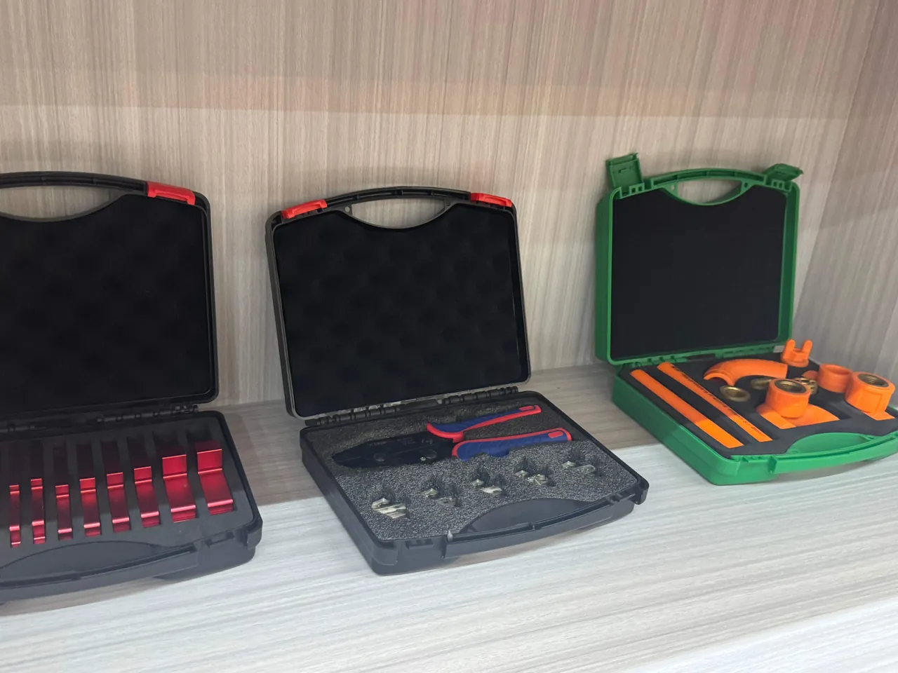
Vertical storage comes first. When boards are stacked horizontally, the lower boards carry the entire weight above them, and creep deformation occurs during long storage. Vertical storage lets the board's own weight be carried by the edge or by dedicated slots, significantly reducing warp risk. This is why the overwhelming majority of PCB transport cases use vertical slot structures.
Board spacing and slot depth. Spacing that is too small lets adjacent boards touch and rub under vibration. Spacing that is too large reduces volumetric packing density and increases board sway amplitude. Slot depth should give enough support length along the board edge without hindering loading and removal. Slot mouths should have large radii or chamfers so that edges are not scored by sharp corners.
Stacking height limits. When vertical cases are stacked, load travels through the case side walls. If side wall stiffness is inadequate, stacking squeezes the walls inward and transfers pressure to the boards. The engineering answer is a stacking stop that routes load through structural columns, together with a clearly stated maximum stacking height.
Special handling for thin and large boards. For ultra-thin boards below about 0.4 mm and for large-format boards, vertical storage can still produce mid-span sag. Adding a central support or limiting the number of boards per case keeps the load on each board within a safe range.
Board edge protection zones. Board edges are the clamping and guidance surfaces and the most likely to be chipped. Compliant protection at the slot base and sides prevents edges from striking hard material directly.
For related cushioning and support concepts, see cushion liner structural design and removable divider systems for protective cases.
7. Inserts and Dividers: Achieving Zero Inter-Board Friction
"Zero inter-board friction" is one of the most concrete engineering objectives for a PCB transport case.
Option one: fixed slot design. Divider spacing is fixed, which suits a single board thickness and width over a long production run. Positioning is precise and spacing is consistent, but changeover is inflexible.
Option two: adjustable dividers. Slots and movable dividers change the spacing, accommodating a range of board widths. Flexibility is good, but the dividers must be verified not to migrate under vibration, and the clearance in the adjustment mechanism itself can become a source of board sway.
Option three: moulded inserts. EVA or foam is moulded to the board contour to create continuous compliant support. This suits finished boards, assembled modules and irregular geometry, with large protective contact areas, at the cost of higher development effort.
Option four: trays with compartments. For small boards or panelised boards, a compartmented tray gives every board its own cell. This effectively prevents board-to-board contact and suits high-volume small-format boards.
Common requirements:
- Material contacting the board should be static-dissipative or conductive, with a smooth, non-shedding surface.
- Contact faces should avoid line contact and sharp corners, favouring area contact or large-radius contact.
- Slots and dividers should be easy to clean, avoiding narrow deep grooves that trap contamination.
- The structure should include poka-yoke features preventing reverse insertion or double stacking.
For finished modules, meaning populated PCBs or PCBAs, component height differences mean the insert must provide clearance at component locations and local support for tall components. For related moulding processes, see custom foam insert solutions and moulding processes and case insert foam material comparison.
8. Case Structure: Stacking, Handling and Automation Compatibility
A PCB transport case is a high-frequency production fixture, and its structure directly affects line efficiency.
Stacking and location. The case should have a stable stacking location feature so that stacked cases cannot shift laterally, together with stacking stops that route load through structural columns rather than through the case rim or the boards.
Handling ergonomics. A fully loaded PCB case has real weight. Handle position and grip shape should support both one-handed and two-handed carrying, avoiding drops caused by awkward handling. Where manual handling is frequent, a caster or trolley solution may be appropriate; see case wheels and trolley handle configuration.
Automation compatibility. On lines with automated loading or AGV transport, the case's external dimensions, bottom locating features and gripping surfaces must match the equipment. This must be confirmed with equipment engineers at the design stage, not discovered as an incompatibility during line integration.
Identification and traceability. Every case needs a clear identification area for batch labels, QR codes or RFID tags. Label positions should not be blocked by stacking surfaces, handles or equipment clamps. Where high-temperature or solvent cleaning is used, the marking method must be selected accordingly.
Latches and hinges. On lidded cases, latches and hinges are wear parts. Choose structures that open and close smoothly, have adequate life, and do not jam on powder or contamination. For related structural selection, see toolbox hinge and latch sealing structures and case lock customisation options.
9. Sealing Levels and IP Protection Selection
Whether a PCB case needs sealing depends on whether the boards are already populated, whether they contain moisture-sensitive devices, and on the transport route environment.
IEC 60529 and GB/T 4208 define enclosure protection classes: 6 in the first digit means dust tight, and in the second digit 5 means water jet resistant, 6 means powerful water jet resistant and 7 means temporary immersion protection. Typical configurations for PCB handling are shown below.
| Scenario | Recommended protection | Notes |
|---|---|---|
| --- | --- | --- |
| Bare board in-plant transfer | IP54 or no sealing | Focus on ESD and scratch prevention, emphasise opening efficiency |
| Bare board inter-plant shipment | IP65 | Dust and water jet protection, used with moisture barrier bag |
| Populated PCBA handling | IP54 to IP65 | Component height and insert clearance must be evaluated |
| Export sea freight | IP67 plus moisture barrier bag | Temporary immersion protection with pressure equalisation |
| High-reliability products | IP67 plus barrier bag plus logger | Emphasises traceability and low-humidity environment |
Two points deserve emphasis. First, an IP rating cannot replace moisture barrier packaging. IP6X addresses particle ingress, while water vapour molecules can pass through the microscopic channels present in most elastomer seals, so real moisture control still depends on the barrier film and desiccant. Second, the fully airtight nature of IP67 amplifies the internal-external pressure differential, and in air freight and high temperature differential scenarios it should be paired with a pressure equalisation valve to prevent the gasket from being drawn inward or the case from bulging. See IP67 protective case applications and selection and the role and selection of case pressure equalisation valves.
10. Cleanliness and Contamination Control: Ionic Residue and Particles
For high-reliability electronics in automotive, medical and avionics applications, contamination control is no less important than ESD and moisture control.
Ionic contamination. Flux activators, halides and salts left on the board surface ionise in the presence of moisture, forming conductive paths that drive dendrite growth and electrochemical migration. Board shops and assembly houses normally have cleaning and ionic contamination test flows, and the transport case's job is not to introduce new contamination sources and not to re-contaminate boards that have already been cleaned.
Particulate contamination. Particles landing on pads affect solder joint quality, and particles inside connectors cause contact faults. Boards handled in cleanroom environments are even more sensitive to particles.
Control measures:
- Case and insert materials should be low-outgassing and low-shedding, avoiding foams that generate wear particles.
- The case should be easy to clean, with no deep narrow grooves or blind holes.
- Where used in a clean area, the exterior should be wiped before entry.
- Use separate cases for products at different cleanliness levels to prevent cross-contamination.
- Establish a cleaning interval and a method for confirming cleaning effectiveness.
11. Standards Reference: The IPC Family, J-STD-033 and Transport Testing
Selection and acceptance of a PCB transport case should be based on the following standards framework.
The IPC family. IPC is the international industry association for electronics manufacturing, and its standards cover printed board performance and acceptance, acceptability of electronic assemblies, test methods, and handling and storage guidelines. The most directly relevant to transport and storage are the printed board handling and storage guideline standards, which cover packaging, moisture barriers, storage conditions and exposure time management, and which are the key basis for turning moisture control into an executable procedure. Related board performance and acceptance standards define the acceptance criteria for the board itself, which help distinguish a board defect from transport-induced damage.
IPC/JEDEC J-STD-033. This standard specifies handling, packing, shipping and use requirements for moisture-sensitive surface mount devices, including the use of humidity indicator cards, desiccant and moisture barrier bags, and floor life management after opening. For populated PCBAs and board assemblies containing moisture-sensitive devices, J-STD-033 is the direct basis for moisture barrier packaging, and its framework can also be used to define desiccant quantity and exposure time rules for transport cases.
IPC/JEDEC J-STD-020. Defines the moisture sensitivity level (MSL) classification method, which is the basis for judging how moisture sensitive a given device is and therefore how strict the packaging and baking strategy must be.
ESD standards. ANSI/ESD S20.20 and ANSI/ESD S541 provide the electrostatic control programme and packaging material requirements respectively, while IEC 61340-5-1 provides the international framework.
Transport and protection standards. ISTA and GB/T 4857 provide vibration, shock and stacking test methods; IEC 60529 and GB/T 4208 define IP classes; UL94 is used to assess the flame retardancy class of plastic materials. On MIL-STD-810H, the boundary must be clear: in this context it is used only as a reference for environmental test methods such as temperature, humidity, vibration and shock. It does not indicate any military certification and does not replace the requirements of IPC or ESD standards. See MIL-STD-810H environmental testing and case compliance for clarification.
12. Transport Verification: Applying ISTA and GB/T 4857
PCB transport case verification has two distinguishing features: judgement must rest on board-level and packaging-level cleanliness, static and humidity metrics, and testing must be carried out in the actual loaded state.
Test design recommendations:
- Sample configuration. Use real boards or scrap boards as ballast, with the loaded quantity, board spacing and retention state exactly matching the actual shipment. Conclusions from an empty case test are usually unusable.
- Test items. At minimum cover vibration (sine sweep or random), drop (at real handling heights and orientations) and stacking (at the real number of layers). Air freight scenarios should add low pressure testing, and long sea freight should add temperature and humidity cycling.
- Post-test inspection. Check whether boards shifted, whether edges were damaged, whether new scratches appeared on board surfaces, whether dividers shifted or collapsed, whether the moisture barrier packaging was punctured, and whether the humidity indicator card changed colour; then re-measure critical dimensions and static performance.
- Acceptance criteria. Agree in advance on permitted board displacement, permitted packaging damage, permitted indicator card state, and the functional and visual acceptance standard.
For method selection, see ISTA transport test procedures and GB/T 4857 transport packaging testing and case verification. Where a common acceptance criterion must be agreed with a customer, see ASTM D4169 distribution cycle testing.
13. Pre-Shipment Inspection and Acceptance Points
Pre-shipment checklist:
- Boards cleaned with ionic contamination and appearance inspection results recorded
- Board dryness state meets requirements, with baking records where applicable
- Case and dividers clean, undamaged, free of embedded grit and permanent deformation
- Boards correctly located in slots, no reverse insertion, no floating caused by warp
- Latches and hinges in normal condition, no looseness when closed
- Moisture barrier bag seal intact, desiccant in date, humidity indicator card normal
- Logger started where fitted
- Identification complete: product model, revision, batch, quantity, orientation and precautions
Acceptance sampling points:
| Check item | Method | Acceptance point |
|---|---|---|
| --- | --- | --- |
| Material surface resistance | Measurement by the agreed method | Within the static-dissipative band, including post-ageing requirement |
| Grounding continuity | Multimeter measurement of bonding resistance | Resistance from insert or divider to grounding terminal within threshold |
| Slot dimensions and spacing | Gauges plus trial fit with real boards | No board movement, no interference, smooth loading |
| Stacking stability | Stack to the maximum stacking height | No lateral shift, no inward squeeze, no rim deformation |
| Sealing (where IP is claimed) | Water spray or immersion test to the rating | No leakage, internal indicator card unchanged |
| Barrier packaging integrity | Visual inspection plus seal check | No puncture, no incomplete seal |
| Humidity indicator card | Read at opening | Within the permitted range |
For volume procurement, introduce an AQL sampling plan and apply tightened sampling to critical characteristics such as surface resistance, grounding continuity, slot dimensions and sealing. For the methodology, see case acceptance and AQL sampling plans.
14. Case Cleaning, Maintenance and Life Management
A PCB transport case is a high-frequency reusable fixture, and maintenance standards directly determine long-term consistency.
Cleaning. Establish a cleaning interval based on contamination level and cleanliness requirements. Cleaning methods must be compatible with the materials: some plastics stress crack in alcohols or alkaline cleaners, and some antistatic agents are extracted by solvents, raising surface resistance. Boards should be fully dried after cleaning and surface resistance re-measured. For general cleaning thinking, see protective case cleaning and maintenance.
Re-measuring static performance. The performance of antistatic and static-dissipative materials decays with time, contamination and cleaning. Establish a periodic re-measurement scheme, sample surface resistance and record results in the fixture file. For high-reliability product lines, surface resistance re-measurement belongs in the fixture calibration system rather than being left to visual judgement.
Wear part replacement. Dividers, slot strips, latches and hinges are wear parts and should be replaced according to usage. A permanently bowed divider or a worn slot mouth directly causes uneven board spacing and increased displacement.
Life and retirement. When a case shows deformation that affects stacking stability, reduced divider location accuracy, or out-of-range surface resistance that cannot be restored by cleaning, downgrade or retirement should be considered. For related thinking, see protective case service life assessment.
15. Common Misconceptions and Engineering Recommendations
Misconception one: "a black plastic box is an antistatic box." Colour has nothing to do with static dissipation. The basis for judgement is measured material resistance, the test method used, and whether dissipative behaviour is durable. Request data during procurement rather than accepting an appearance-based claim.
Misconception two: "an IP67 case needs no moisture barrier packaging." An IP rating addresses solid particles and liquid water ingress, while water vapour molecules can still pass through most seals. Real board-level moisture control depends on the barrier film and desiccant, and the IP rating is only outer reinforcement.
Misconception three: "just throw in a few desiccant sachets." Desiccant quantity should match internal volume, initial humidity, transport duration and barrier transmission rate. Undersizing leads to failure late in the journey, when nobody notices.
Misconception four: "horizontal stacking saves more space." Horizontal stacking makes lower boards carry weight over the long term, which is a major cause of warp. Vertical slot storage is the more robust choice.
Misconception five: "boards are tough, so anything goes." The bare board is reasonably strong, but the components, gold fingers and fine traces on it are highly sensitive to friction, static and humidity. Failure is usually chronic damage rather than a broken board.
Summary of engineering recommendations:
- Write measured surface resistance and post-ageing data into the procurement specification rather than just the phrase "antistatic".
- Make moisture barrier packaging, desiccant quantity and exposure time management part of the work instruction, closing the loop from opening to use.
- Prefer vertical slot storage and use stacking stops to route load into structural columns.
- On automated lines, confirm case outline and gripping features against equipment requirements in advance.
- Choose a supplier able to provide inserts, dividers and case structure as an integrated package matched to board format and line interfaces. Through the moulding and tooling capability of Kexin New Materials (Guangdong) Co., Ltd., JUNZHJIA can configure inserts, dividers, gaskets and case structures to match customer board specifications, cleanliness requirements and automation interfaces, supports OEM/ODM and volume supply, and can provide material statements and test documents for acceptance.
Frequently Asked Questions
Q: What metric actually defines whether a PCB transport case is antistatic?
A: The core metric is the measured surface resistance or volume resistance of the material, not the colour or the product name. Three things should be evaluated. First, the resistance band the material sits in. Static-dissipative materials are positioned so that charge drains at a controlled rate, being neither fully insulating nor rapidly conductive. Second, the measurement method. Different electrode geometries, applied voltages and ambient humidity significantly affect readings, so the specification should state the test conditions. Third, durability data, including the initial value and the re-measured value after ageing or after cleaning. A product that only commits to the initial value may be out of band six months later. Note also that an antistatic case does not automatically mean a protected board. A grounding path is needed to take charge to ground, and handling measures such as wrist straps, bench surfaces and disciplined movement reduce charge generation. During procurement, request verifiable test reports and include surface resistance re-measurement in the fixture inspection scheme.
Q: If the case is already IP67, is moisture barrier packaging still needed?
A: Yes, because the two address different problems. An IP rating under IEC 60529 and GB/T 4208 defines the enclosure's protection against solid foreign objects and liquid water. IP6X means dust tight and prevents particle ingress, but water vapour molecules are far smaller than liquid droplets and can pass through the microscopic channels in most elastomer seals and diffuse through the material itself. Even with an IP67 case, internal humidity will rise slowly over long sea freight or in a high-humidity environment. The real barrier against moisture for boards is low-transmission barrier film plus an adequate quantity of desiccant. The IP rating is only outer reinforcement, protecting against water jets, temporary immersion and particles. The correct combination is an IP rating plus a moisture barrier bag plus desiccant plus humidity indication, where the barrier bag and desiccant form the first line of defence against moisture and the case forms the outer mechanical and environmental line.
Q: How should desiccant quantity be determined?
A: Not by experience, but by calculation and worst-case validation. The inputs required include the net internal volume of the package after deducting board and insert displacement, the initial humidity of the air inside at sealing, the total transport and storage duration, the moisture vapour transmission rate of the barrier material, and the worst-case combination of external temperature and humidity. Desiccant absorption capacity varies with temperature and humidity and has a saturation limit, so sizing should estimate the total moisture that could enter the package over the full cycle and then add safety margin. For long sea freight, size against high temperature, high humidity and maximum duration rather than average conditions. In practice, a two-tier approach works well: standard configuration for routine shipments, and increased quantity with a humidity indicator card or logger for long-duration or high-value batches, so that the package can be validated at opening. If the indicator card has changed colour on opening, bake the boards according to procedure and trace the affected scope.
Q: Why should PCBs not be stored in horizontal stacks for long periods?
A: Because horizontal stacking makes lower boards carry the cumulative weight of everything above them as a sustained static load. Under long-term load and temperature, resin substrates creep, which appears as slow board curvature. The greater the stack height, the longer the storage period and the higher the ambient temperature, the more pronounced the deformation. Horizontal stacking also places board surfaces in direct contact, which readily causes solder mask and trace scratches during handling and allows residues on one board to transfer to the next. Vertical slot storage, by contrast, lets the board's own weight be carried mainly by the board edge or dedicated slots, keeps surfaces separated, and both reduces warp risk and prevents inter-board friction. This is why the vast majority of PCB transport cases use a vertical structure. Note that with vertical storage, slot spacing, slot depth and case side wall stiffness must be matched, otherwise stacking squeezes the side walls inward and still transfers pressure to the boards.
Q: What special requirements apply to shipping PCBAs containing moisture-sensitive devices?
A: Board assemblies containing moisture-sensitive surface mount devices have stricter moisture requirements than bare boards, and should follow the handling, packing, shipping and use framework of IPC/JEDEC J-STD-033, covering humidity indicator cards, desiccant, moisture barrier packaging requirements and floor life management after opening. The underlying logic is that both the device and the board absorb moisture, and during reflow the vaporised internal moisture creates pressure that causes delamination, blistering or internal cracking, so absorbed moisture must be kept within what the process can tolerate. Three practical points matter. First, use the J-STD-020 classification to establish the moisture sensitivity level of the devices involved, since higher levels require stricter packaging and baking. Second, maintain a record of opening time, elapsed exposure and remaining floor life, and bake when the limit is exceeded. Third, packaging and the transport case are two separate layers: the case provides mechanical and static protection while the barrier packaging provides moisture protection, and neither substitutes for the other.
Q: Does a transport case need testing, and to what methods?
A: Yes, particularly after a new structure is finalised, an insert material is changed, a board format changes, or the loading method changes. The ISTA series can be used by selecting the procedure matching the transport scenario. Domestic projects can reference the vibration, shock, stacking and compression test methods in the GB/T 4857 series. Where a common acceptance criterion must be agreed with a customer, ASTM D4169, based on the distribution cycle, is appropriate. Three design points matter. First, use real boards or equivalent ballast with the loaded quantity, board spacing and retention state matching the actual shipment, because conclusions from an empty case test are usually unusable. Second, ensure the test orientations and items cover the real risks, including drops in different orientations and stacking at the actual number of layers, and add low pressure testing for air freight. Third, ensure post-test judgement sits at the board and packaging level, covering whether boards shifted, whether new damage appeared at edges and surfaces, whether dividers shifted or collapsed, whether barrier packaging was punctured, and whether the humidity indicator card state is normal.
Q: How often should the surface resistance of an antistatic transport case be re-measured?
A: There is no single interval. Determine it from usage intensity, cleaning frequency and the reliability class of the product, and write it into the fixture management procedure. Antistatic performance decays through three routes: time, since surface-migrating antistatic agents lose effectiveness over time; contamination, since board residues, flux and oils change the surface conduction path; and cleaning, since some cleaners extract antistatic components or cause surface stress cracking. A common approach is to run a full confirmation when a new fixture is accepted, sample periodically during normal use by quarter or by cycle count, sample again after every cleaning, and bring re-measurement into the fixture calibration system for high-reliability lines. If the measured value falls outside the static-dissipative band and cleaning cannot restore it, stop using the case for static-sensitive products and downgrade it to non-sensitive materials. Keep records as the basis for life decisions and traceability. Where results drift steadily in one direction across successive checks, investigate the cleaning agent and the storage environment before condemning the whole batch of fixtures.
Q: Why do dividers become a failure source?
A: Because a divider is both a locating feature and a load-bearing feature. It carries the combined effects of board self weight, vibration inertial force and stacking compression, and its dimensional accuracy directly determines board spacing. Three failure modes are common. First, permanent bowing: the divider deforms irreversibly under long-term load, making spacing uneven with local gaps that are too large or too small. Second, slot wear: boards micro-slide under vibration and wear indentations or burrs into the slot mouth, and burrs scratch board edges and surfaces directly. Third, migration: adjustable dividers creep under vibration and change the spacing that was originally set. In addition, if the divider material loses antistatic performance or becomes contaminated, it can become a charge accumulation point. Countermeasures include selecting static-dissipative and wear-resistant divider materials, adding anti-loosening features to adjustable dividers, establishing a divider replacement plan, and specifically checking divider displacement and slot wear after transport testing.
Conclusion and Further Reading
The challenge in designing a PCB transport case is converging four interconnected failure mechanisms, static, moisture, friction and warp, into one deliverable fixture. Static protection depends on both material resistance and a grounding path. Moisture control depends on barrier packaging and correctly calculated desiccant quantity. Scratch prevention depends on low-friction contact faces and appropriate board spacing. Warp resistance depends on vertical storage and a well-designed load path. None of the four can be solved with a single metric, and none can be judged by appearance or colour.
Four disciplines matter in implementation. Write measured surface resistance and post-ageing data into the procurement specification and bring re-measurement into a periodic scheme. Turn moisture barriers, desiccant quantity and exposure time management into a closed-loop work instruction. Prefer vertical slots and stacking stops that route load into structural columns. On automated lines, confirm the compatibility of case outline and gripping features in advance. When selecting a supplier, focus on whether they can provide inserts, dividers and case structure as an integrated package matched to board specifications and line interfaces, and whether they can provide verifiable material and test documents. Through the moulding and tooling capability of Kexin New Materials (Guangdong) Co., Ltd., JUNZHJIA provides custom inserts, matched dividers and seals, OEM/ODM and volume supply across its protective case, tool case and equipment case product lines. Adjacent electronic and semiconductor material protection needs are covered further in Wafer Transport Cases: Cleanroom & Shock Protection for Semiconductor Wafers and industrial PC and edge computing equipment transport protection.
Further Reading