

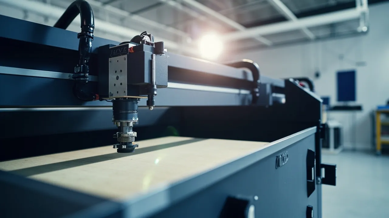
Protecting a laser cutting machine in transit runs into one central conflict: a single machine contains two classes of component whose protection requirements are directly opposed. The laser source is a heavy, impact-sensitive energy source whose mounting datum must not shift. The optical head and the lenses inside it are extremely light, contamination-sensitive, moisture-sensitive precision optics. The correct selection logic for a laser cutting machine case is therefore zoned protection, graded vibration isolation and clean, humidity-controlled enclosure, not one case and one insert for every component. A laser source body typically weighs anywhere from tens of kilograms to several hundred kilograms, and its internal resonator, fibre coil or gas circulation structure is highly sensitive to shock acceleration. The collimating, focusing and protective lenses inside the optical head carry coatings that, once scratched by a particle or attacked by moisture, cannot be recovered by cleaning and must be replaced outright. If those two classes of component travel in the same cavity, the inertial load of the heavy item is transmitted through the insert directly into the optics and causes irreversible damage.
The practical pain points cluster in four areas. The first is misalignment caused by shock and vibration. Once an internal optical element in the laser source shifts by a small amount, output power, beam mode and beam quality all change, and at the cutting end this appears as a rough cut face, dross and a widened kerf; a shifted lens inside the optical head produces focus drift that makes thin-sheet cutting unstable. The second is contamination and scratching of optical surfaces. Dust, metal spatter and oil mist from the cutting process are aggressive contaminants, and if protection during transport and storage is inadequate, particles settle on lens surfaces while on-site staff wiping them with whatever paper is at hand scratch the coating. The third is moisture and condensation. Optical coatings are usually multilayer dielectric stacks that are moisture-sensitive, and condensation inside a sea freight container crossing climate zones causes hydrolysis, mould growth and delamination of the coating. The fourth is packing and reassembly efficiency. Laser cutting machines are usually installed and commissioned at the customer site, and if the case cannot support on-site reassembly, temporary storage and a second move, service cost and downtime rise sharply.
This article works through the protection logic in the order of laser source, optical head and optical elements, vibration isolation and cleanliness, sealing and testing, and acceptance and export. It provides a laser type comparison table, an optical component protection table, cleanliness and humidity control points, sealing class recommendations and a transport test plan, together with a specification selection table and an acceptance checklist. JUNZHJIA serves laser equipment manufacturers, laser cutting machine integrators, laser service providers and equipment rental companies with heavy-duty vibration-isolating case design, clean optical cavity inserts, custom cavities, component-matched isolation and sealing schemes, and OEM/ODM volume delivery, manufactured and shipped worldwide by Kexin New Materials (Guangdong) Co., Ltd.
Table of Contents
- 1. Why Laser Cutting Equipment Needs Purpose-Built Cases
- 2. Risk Profile: Failure Modes of Laser Source, Optical Head and Following System
- 3. Laser Source Types: CO2, Fibre and Solid-State Differences
- 4. Protecting the Optical Head: Cutting Head, Focusing Lens and Protective Lens
- 5. Laser Safety Boundary: Transport and Delivery in the IEC 60825 Context
- 6. Cleanliness and Particle Control: Managing Optical Surface Contamination
- 7. Humidity and Condensation Control: Desiccants and Moisture Barrier Packaging
- 8. Vibration Isolation and Cushioning: Graded by Component
- 9. Sealing Class: How IEC 60529 and GB/T 4208 Apply
- 10. Custom Inserts: Laser Source Cavity, Optical Head Cavity and Accessory Cavity
- 11. Transport Testing: ISTA, GB/T 4857 and ASTM D4169
- 12. Marking, Documentation and On-Board Spare Management
- 13. Procurement Acceptance, AQL and Specification Selection Table
- 14. Export, Storage and On-Site Reassembly Points
- Frequently Asked Questions
- Conclusion & Related Reading
1. Why Laser Cutting Equipment Needs Purpose-Built Cases
The starting point for understanding transport protection of a laser cutting machine is the fact that one machine contains two physical logics.
The laser source is an energy source, and its protection logic is structural integrity and datum stability. Whether the machine uses a CO2 laser, a fibre laser or a solid-state laser, the interior contains a precision optical resonant structure: the discharge tube and mirror set of a CO2 laser, the active fibre coil plus fibre Bragg gratings of a fibre laser, or the crystal and cavity mirrors of a solid-state laser. What these share is that their installed positions are established by optical alignment, and once a small displacement occurs the beam path no longer matches the design. The sources of displacement are mainly shock and sustained vibration. The first objective of laser source protection is therefore to limit the shock acceleration and vibration level transmitted to the laser body, not simply to make the case thicker.
The optical head is a precision optical assembly, and its protection logic is surface cleanliness and positional fixation. A cutting head usually contains a collimating lens, a focusing lens and a protective lens, and in some designs also mirrors and beam splitters. These carry multilayer dielectric coatings whose layer thickness is measured in micrometres or less. Any particle, even dust of a few micrometres, that lands on the coating can be ablated under high-power laser irradiation and damage the coating; any scratch creates a scattering point that cannot be repaired. At the same time, the axial position of the lens directly determines the focal position, so a small axial displacement of the lens produces focus drift. The first objective of optical head protection is therefore clean enclosure and axial location.
The load magnitudes of the two component classes differ by more than two orders of magnitude, which is why zoning is mandatory. A 6 kW fibre laser may weigh over 200 kg while an optical head often weighs under 5 kg. If both share one cavity, a heavy laser source develops a large inertial displacement during transport, and its momentum passes through the insert into the optical head. Even a cushioned insert compresses fully within milliseconds, leaving too little stroke to protect the optics. This is the physical basis for zoning, not a rule of thumb.
On-site reassembly and turnaround efficiency is the third design objective. After delivery, a laser cutting machine must be installed, its beam path checked and its cutting parameters calibrated at the customer site. Many integrators keep the transport case as an on-site storage and second-move tool. That means the case should open and close easily, allow components to be taken out in a clear order, be reusable, and have a reusable seal. A case that can only be used once, whose insert is destroyed on opening, simply shifts cost into the field service stage.
In summary, the core requirements for a laser cutting machine case are load-bearing and vibration isolation for the heavy laser source, clean enclosure and axial location for the optics, physical zoning of the two component classes, and a reusable structure that matches the on-site reassembly workflow. A general selection framework is set out in the Instrument case selection guide.
2. Risk Profile: Failure Modes of Laser Source, Optical Head and Following System
The logistics chain for laser cutting equipment is typically: equipment plant or laser source plant, integrator assembly workshop, customer site via long-distance road, rail or sea freight, then on-site installation and commissioning. There are many stages, many loading and unloading cycles, and frequently several climate zones.
| Chain stage | Dominant stress | Typical consequence | Protection focus |
|---|---|---|---|
| --- | --- | --- | --- |
| Laser source dispatch | Shock, sustained vibration, temperature swing | Internal optic displacement, fibre coil state change | Graded isolation, attitude fixation, thermal buffer |
| Integrator assembly and transfer | Short moves, frequent lifting | Shell impact damage, interface damage, coolant line compression | Reinforced lifting points, interface protection, line limits |
| Long-haul road and rail | Low-frequency vibration, random shock, humidity swing | Resonator misalignment, lens shift, fastener loosening | Low-frequency isolation, anti-loosening design, humidity control |
| Sea freight export | High humidity, heat, condensation, repeated handling | Coating hydrolysis, mould, corrosion, condensation | IP67 plus pressure equalisation valve plus desiccant |
| Customer site storage and reassembly | Repeated opening, dust, temporary storage | Optical surface contamination, insert damage, mixed components | Reusable seal, clean insert, position numbering |
Shock-induced misalignment is the primary failure mode of a laser source. Internal optical elements are held by mechanical structures whose acceleration tolerance is limited. Common industry practice is that the packaging design for a laser body must limit shock acceleration, and the specific limit should be provided by the laser manufacturer based on the internal structure and optical alignment tolerance. The values differ widely between models and power classes and cannot be replaced by a single number. It is worth stressing that misalignment caused by shock often shows no visible external damage on opening; instead it appears at the cutting end as process parameters that cannot be reproduced. This kind of hidden failure is the hardest problem in laser equipment transport.
Sustained vibration causes progressive displacement. Road transport vibration is dominated by low frequencies, often in the range of a few hertz to a few tens of hertz, and that band readily excites rocking motion in heavy components. If the insert merely pads with soft material without forming a stable multi-axis constraint, the laser source micro-moves throughout the journey, fasteners gradually loosen and internal optical mounts gradually drift. The core of insert design is therefore constraint rather than padding: multi-axis location, rigid support faces and a controlled cushion layer combine to attenuate vibration energy stage by stage along the transmission path.
The failure modes of the optical head are entirely different. The main risks are lens surface contamination from settled particles, oil mist and fingerprints; lens scratching from improper cleaning or contact with hard objects; lens axial displacement from shock loosening a retaining ring or shifting a lens mount; coating moisture attack causing hydrolysis and interfacial delamination; and deformation of collimating and focusing assemblies from thin-wall barrel compression. The hardest to handle is coating moisture attack: heat and humidity combined with condensation in a sea freight environment cause hydrolysis and mould in multilayer dielectric stacks, showing up as reduced transmission and increased scattering, and ultimately as insufficient output power and degraded cutting capability.
The following system and sensors are the third risk class. Modern cutting heads commonly carry capacitive or mechanical height following systems, including a ceramic ring, sensing circuitry, a moving guide mechanism and a bellows boot. These are fragile and difficult to replace individually: the ceramic ring chips, the bellows boot deforms under compression and the sensing circuit is static-sensitive. Protection means a dedicated cavity, a rigid guard and ESD-safe packaging, never sharing a cavity with heavy components. Related ESD design thinking is set out in ESD shielded protective case design.
Cooling and gas circuit accessories are easily overlooked. A laser source is usually paired with chiller interfaces, deionised water circuits, gas fittings and pressure sensors. The metal fittings on these accessories are common sites of impact deformation, and once deformed the sealing face leaks. Protection means protective caps on fittings, dedicated accessory cavities and controlled line bend radius.
3. Laser Source Types: CO2, Fibre and Solid-State Differences
Different laser types have clearly different transport protection requirements and must be designed separately.
CO2 lasers typically consist of a discharge tube in glass or ceramic, a mirror set, an output window and a gas circulation system. Their vulnerabilities are that the discharge tube is glass or ceramic and vulnerable to shock and compression, the cavity mirror positions and angles are set by optical alignment and vulnerable to vibration-induced misalignment, and the output window, usually ZnSe or GaAs, is sensitive to moisture and scratching and the material itself is moisture-sensitive. Protection means axial multi-point equidistant support of the discharge tube to avoid bending stress from single-point or two-end support, fixation of cavity attitude with limited rotation about the axis, separate dry sealed packaging for the output window, and low-frequency isolation for the whole unit.
Fibre lasers consist of pump sources, a gain fibre coil, fibre Bragg gratings, a combiner and an output isolator, all enclosed in the housing and connected to an output interface. Their vulnerabilities are that the active fibre has a minimum coil radius and compression or an undersized radius raises loss or even breaks the fibre, the fibre gratings and combiner are sensitive to vibration and rapid temperature change, and the output delivery fibre, whether QBH or QD, is among the most fragile parts of the whole system. Protection means graded isolation for the housing, and critically a dedicated cavity for the output delivery fibre with a controlled bend radius, a capped and cleanly packaged end face, plus avoiding handling at low temperature where the fibre coating becomes brittle.
Solid-state lasers, including rod, slab and disk designs, and ultrafast lasers are even more sensitive to shock and temperature. Their vulnerabilities are that the alignment precision required between crystal and cavity mirrors is extremely high, some designs are sensitive to temperature gradients through thermal lensing behaviour, and ultrafast laser internal beam paths are usually more compact and extremely sensitive to displacement. Protection means a higher grade of isolation and attitude fixation, control of the rate of temperature change in transport and storage, and shock recording inside the case using impact indicator labels so that a post-arrival check can determine whether limits were exceeded.
Diode pump and fibre-coupled modules are small and light but equally vulnerable to vibration and static. Protection means ESD-safe packaging, a dedicated cavity and end face protection.
| Laser type | Vulnerable parts | Main failure modes | Protection strategy | Key prohibitions |
|---|---|---|---|---|
| --- | --- | --- | --- | --- |
| CO2 laser | Discharge tube, cavity mirrors, output window | Glass breakage, mirror misalignment, window moisture | Axial multi-point support, attitude fixation, dry sealed window | No single-point support, no inversion |
| Fibre laser | Active fibre coil, fibre gratings, delivery fibre | Coil compression, rising loss, end face contamination | Graded isolation, dedicated fibre cavity, controlled radius, end caps | No small-radius bends on the delivery fibre |
| Solid-state and ultrafast | Crystal, cavity mirrors, compact beam path | Alignment instability, thermal gradient effects | High-grade isolation, thermal buffer, shock recording | No rapid temperature change, no stacking load |
| Pump and coupling modules | Fibre-coupled end face, driver circuitry | End face contamination, ESD damage | ESD-safe packaging, dedicated cavity, end face protection | No bare-hand contact with end faces |
4. Protecting the Optical Head: Cutting Head, Focusing Lens and Protective Lens
The optical head is the working end of a laser cutting machine and the most difficult component to protect.
Structural characteristics of the cutting head. A modern cutting head integrates a collimating lens group, a focusing lens group, a protective lens drawer, a gas nozzle, a height following sensor and a cooling water circuit. It usually weighs under a few kilograms but is compact, contains many thin-wall parts and is sensitive to compression. Its failure modes include barrel deformation from compression, which changes lens position and causes focus drift; protective lens drawer jamming from ingested particles or deformation; nozzle impact damage, where deformation of the nozzle orifice directly affects cut quality and the gas flow field; ceramic ring fracture; and water circuit fitting leakage.
The protective lens is the most frequently sacrificed and the most important consumable in the system. Its job is to block spatter and fume and protect the far more expensive focusing lens. In transport and storage the risks to a protective lens are surface particle settlement, which causes ablation the moment the machine is powered up after installation; outgassing contamination from packaging materials, since some plastics release plasticisers or siloxanes that form a hazy film on the lens surface; and moisture attack causing coating hydrolysis. Protective lens packaging should therefore use silicone-free, low-outgassing cleanroom-compatible materials together with a desiccant and a clean bag.
Protection points for the focusing and collimating lenses. These are usually fused silica or special optical glass substrates with an anti-reflective coating. The key points are reliable axial location, so that the lens retaining ring does not loosen under vibration; no radial compression, so that the interface between lens and mount uses a suitable compliant pad rather than rigid contact, avoiding stress birefringence; moisture-sealed mounts; and cleanroom packaging, with the lens placed individually in a clean bag and a rigid protective box.
Recommended scheme for transporting the optical head as a unit. Place the whole head in a custom cavity where the cavity matches the head profile and creates surface contact rather than point contact. Nothing may be stacked directly above the optical head. Fit a rigid guard over the nozzle and ceramic ring. Spare lenses travelling with the machine go into dedicated clean boxes in a separate cavity from the head body. Spare lenses must be separated from tools and consumables by case or by cavity, because the metal particles and abrasive dust generated by wrenches, nozzles and abrasives in transit are lethal contaminants for a lens surface.
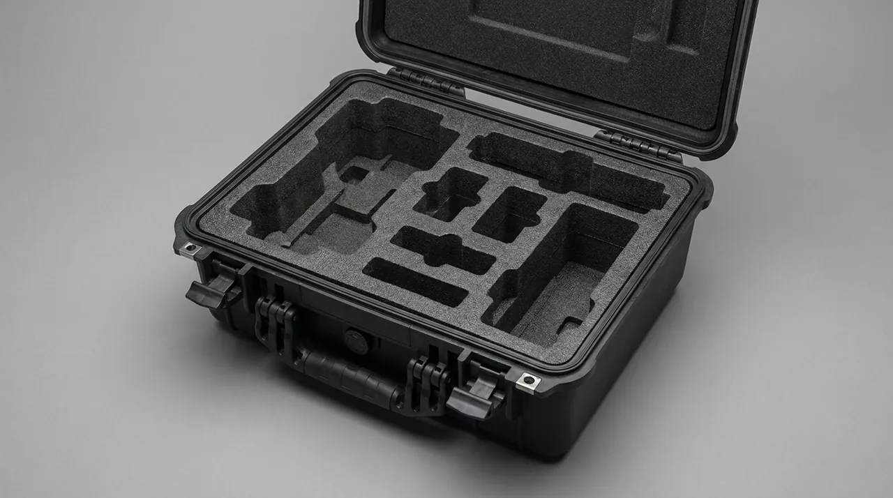
On the boundary of cleaning operations. The correct on-site practice for cleaning a lens is to use dedicated optical wipes and solvent, wiping in a single direction rather than rubbing back and forth, and to prefer replacing the protective lens rather than repeatedly cleaning the focusing lens. The case design should support that working habit: for example by providing a dedicated clean consumables cavity holding wipes, solvent bottles and clean gloves, so that staff do not improvise with whatever is available on site.
5. Laser Safety Boundary: Transport and Delivery in the IEC 60825 Context
Laser product safety classification and operational protection sit within a clear international standards framework, and understanding that framework has practical value for transport scheme design.
The IEC 60825 series is the core standards framework for laser product safety. It defines laser product classes such as Class 1, Class 2, Class 3R, Class 3B and Class 4, accessible emission limits, safety labelling and information requirements. Industrial laser cutting machines are usually equipped with Class 3B or Class 4 lasers, and their operation, maintenance and servicing carry strict protection requirements.
The relationship between the standard and the transport scheme must be understood accurately. Laser safety standards govern protection against laser radiation hazards; they do not directly prescribe structural requirements for transport packaging. The practical relevance is in three areas. First, marking and information: laser warning labels and necessary safety information should be retained on the case and in the accompanying documentation so that hazards are clearly indicated at every stage of unpacking, handling and installation. Second, delivery state management: the equipment should be in a non-emitting state during transport, for example with the key switch removed, the emergency stop in the open position and the control system shut down, and that state should be recorded in the packing list and delivery notes. Third, documentation completeness: the laser safety manual, operating manual and spare warning labels should travel with the goods, stored where they are protected from moisture and contamination.
It must be stated clearly that the protective case discussed here is a transport and storage protection structure. It is not a laser safety guard and cannot replace any laser safety management requirement. Commissioning, servicing and operation of laser equipment must be performed by qualified personnel in accordance with applicable regulations, standards and company procedures, using appropriate protective equipment. No scheme described here may be interpreted as exempting anyone from laser safety management requirements.
Practical risk points in transport and storage include a service window or protective cover opening under vibration and exposing the internal beam path; optical components being taken out for a casual look without protection and becoming contaminated or causing injury; on-board tools being stored with optical components and damaging optical surfaces; and the case being treated as ordinary cargo and stacked, compressing internal parts. These risks can be substantially reduced by structural design, for example by providing an unpacking notice position on the case, arranging cavities in the intended removal order, and physically separating the tool cavity from the optical cavity.
6. Cleanliness and Particle Control: Managing Optical Surface Contamination
Cleanliness control is the capability that distinguishes optical protection from general industrial protection, and this chapter gives workable engineering practice.
Where contaminants come from. Optical components encounter five main classes of contaminant in transport and storage: particles such as metal dust, abrasive dust, paper debris and fibre; oil mist and organic vapour from lubricants, cutting fluid and packaging material outgassing; water vapour and condensate; fingerprints and skin oils; and micro-organisms that grow as mould in hot, humid conditions. Particles and organic vapour are the two main killers: particles absorb energy under high-power laser irradiation and are ablated, creating permanent damage sites, while organic vapour forms a thin haze layer on the lens surface that reduces transmission.
Three levels of clean packaging. The first level is packaging of the optical component itself: lenses go into dedicated clean bags or boxes, optical faces never contact the packaging material directly, and optical-grade pad materials are used where needed. The second level is cavity isolation: the optical cavity must be physically separated from the tool, consumable and spare cavities so dust cannot migrate freely in transit. The third level is overall case sealing and cleanliness: the sealing class of the case determines the rate at which external dust enters, and the better the seal the longer internal cleanliness is maintained.
Key constraints on material selection. Materials that contact optical components directly or indirectly must deliver low outgassing, releasing no siloxanes, plasticisers or condensable volatiles; low particle shedding, generating no fibre or particles through friction; no scratching, with controlled surface hardness and roughness and no hard fillers; and chemical inertness, not reacting with optical coatings. This is the biggest difference between optical inserts and conventional packaging inserts. Many general-purpose packaging foams continuously release condensable volatiles that accumulate inside a sealed case and deposit on lens surfaces as a haze that is very difficult to remove. In optical applications, insert materials must therefore be evaluated for outgassing and verified under actual use conditions. A comparison method is given in the Case foam material comparison.
Assembly and unpacking cleanliness matters just as much. No packaging can compensate for leaving components open for hours in a dusty environment. Delivery documentation should therefore state unpacking requirements: open the case in a clean area, clean the bench and tools beforehand, wear clean gloves and a mask, load optical components immediately or transfer them to a clean container, and avoid any dust-generating work such as grinding or cutting while the case is open.
| Contaminant type | Source | Effect on optics | Control measure |
|---|---|---|---|
| --- | --- | --- | --- |
| Particles | Metal dust, abrasives, paper, fibre | Ablation under high power, permanent damage sites | Clean packaging, cavity isolation, case sealing |
| Oil mist and organic vapour | Lubricants, packaging outgassing | Surface haze, reduced transmission | Low-outgassing materials, no shared tool cavity |
| Water vapour and condensate | Ambient humidity, condensation from temperature swings | Coating hydrolysis, delamination, mould | Sealing plus desiccant plus thermal buffer |
| Fingerprints and skin oils | Bare-hand contact | Localised absorption, coating damage | Clean gloves, no-touch notices, separate access |
| Micro-organisms | Hot, humid environment | Mould spots, coating degradation | Humidity control, desiccant, periodic inspection |
7. Humidity and Condensation Control: Desiccants and Moisture Barrier Packaging
Humidity is the number one environmental threat to optics in cross-border transport and long-term storage and requires dedicated design.
How humidity damages optics. Multilayer dielectric coatings are built from alternating layers of materials with different refractive indices, and interfaces exist between layers. When relative humidity stays high for a long period, water molecules diffuse along coating defects and interfaces and cause hydrolysis of coating materials; delamination and separation can occur at interfaces; metal or certain oxide layers may oxidise and corrode; and mould can grow on organic surfaces, leaving permanent scattering sources. High humidity combined with temperature swings also produces condensation, and liquid water on a lens surface is far more damaging than water vapour.
The mechanism of condensation and how to prevent it. Condensation occurs when a surface temperature falls below the dew point of the surrounding air. Two situations are typical in transport. The first is a sea freight container crossing climate zones, where falling night-time outside temperatures cool the container walls and water vapour in the internal air condenses on the walls and on the cargo, a phenomenon often called container rain. The second is moving directly from a cold store into a hot, humid environment, where the cargo surface is below the dew point of the new environment and condenses immediately. There are three prevention threads: reduce the absolute water content inside the case through sealing, desiccant and packing in the driest practical environment; slow the rate of temperature change, since the thermal inertia of the case material delays temperature change so that the cargo surface lags the environment and the condensation window shrinks; and avoid abrupt transfers, allowing goods taken from a cold environment to equalise in temperature before opening.
Desiccant selection and quantity. Common desiccants include silica gel, molecular sieve and clay types. Selection points are adsorption capacity matched to the target humidity, since the recommended storage humidity for optics is typically below 50 percent RH and the specific limit should be given by the optics or equipment manufacturer because different coating and cementing structures tolerate humidity differently; adsorption rate matched to the transport duration, with fast-acting but limited-capacity types for short journeys and high-capacity, long-lasting types for ocean freight; no dust or corrosive by-products; and indicating types whose colour change allows a visual check on opening. Quantity must not be estimated casually. It should be calculated from the free internal volume, the moisture vapour transmission rate of the packaging materials, the transport duration and the target humidity, with an allowance added.
Combining sealing with pressure equalisation. A high sealing class introduces a new engineering problem: when a case is sealed at low altitude and transported at high altitude or by air, the pressure differential imposes extra structural load and makes the case hard to open. Cases with IP67 or above used for optical equipment should therefore be fitted with a pressure equalisation valve, which allows slow air exchange once the differential reaches a threshold while a hydrophobic and oleophobic membrane blocks liquid water and particles. Relevant structure and selection points are given in Case pressure equalisation valve and IP67 protective case structure.
Additional measures for long-term storage. Where equipment is stored in its case for long periods, for example a backup machine or a rental fleet in rotation, it is advisable to inspect the desiccant and internal humidity periodically, for example quarterly; replace the desiccant after every opening; place a humidity indicator card inside the case and state the acceptable range in the delivery documentation; and use a temperature and humidity controlled store where available. Protection thinking for extreme temperatures is set out in Extreme temperature protective cases, and consumable replacement and care in How to clean a protective case.
8. Vibration Isolation and Cushioning: Graded by Component
Vibration isolation is the capability that sets a laser cutting machine case apart from general industrial cases, and the design must be graded by component.
First, distinguish the two load types. Shock is a short-duration, high-amplitude acceleration event caused by drops, impacts, emergency stops and potholes, characterised by a duration of milliseconds and a high peak. Vibration is sustained, low-amplitude oscillation caused by vehicle motion, engine running and road excitation, characterised by long duration and energy concentrated in specific frequency bands. The countermeasures differ: shock needs sufficient cushion stroke and a suitable energy-absorbing material, while vibration needs an appropriate natural frequency and adequate damping to keep the system out of resonance.
The basic principle of grading. Divide the contents into three sensitivity levels: level one for optics and the laser source body, the most sensitive, needing the highest grade of isolation and attitude fixation; level two for electronic control units, sensors and cooling accessories, moderately sensitive, needing conventional cushioning and fixation; and level three for housings, guards, tools and consumables, relatively insensitive, needing protection against impact and abrasion. Different levels must not share a cavity or a cushion layer, because a cushion layer is designed for a specific weight and sensitivity and mixing defeats that design.
Avoid the padding-more-is-better trap. This is the most common design error. Cushion material must be matched to component weight: a material that is too soft compresses fully under a heavy load, loses its cushion stroke and lets the component strike the case wall, while a material that is too hard cannot absorb shock energy and transmits it almost unchanged. Cushion thickness and material hardness must therefore be calculated from component weight, the allowable acceleration limit and the expected drop height, and verified by test. Common industry practice is to establish the allowable acceleration limit as given by the equipment manufacturer, then use cushion curves to select material and bearing area.
Handling low-frequency vibration. Road transport vibration energy sits in the low-frequency band, and if the natural frequency of the isolation system falls inside the excitation band, resonance amplification occurs. Isolation design therefore needs a low system natural frequency through suitable elastic support and mass distribution, added damping to suppress the resonance peak, and multi-axis constraint to limit horizontal and rotational degrees of freedom. For heavier laser sources a common approach is elastic support underneath plus lateral location plus top clamping, so that the component is constrained in all three axes while retaining controlled elastic travel. Related cushion structure design is covered in Cushion liner case design and Shock-sealed case design.
Attitude and degree-of-freedom management. The laser source and optical head should retain their design attitude in transit. The degrees of freedom to constrain are vertical bounce, limited by top clamping or stop blocks; horizontal translation, limited laterally; rotation about a horizontal axis, controlled by supporting both sides of the centre of gravity; and rotation about the vertical axis, constrained by asymmetric stops or friction. Filling the gaps alone cannot constrain all degrees of freedom; a structured insert design is required.
| Component level | Representative parts | Allowable condition (typical practice) | Insert scheme | Verification |
|---|---|---|---|---|
| --- | --- | --- | --- | --- |
| Level one | Laser source body, optical head, lens sets | Per manufacturer acceleration limit | Graded isolation plus multi-axis location plus clean packaging | Shock and vibration test plus shock recording |
| Level two | Control units, sensors, cooling accessories | Conventional industrial equipment level | Cushioned fixation plus dedicated cavity | Vibration and drop test |
| Level three | Housings, guards, tools, consumables | Impact and abrasion protection | Separated fixation plus surface protection | Visual and appearance inspection |
9. Sealing Class: How IEC 60529 and GB/T 4208 Apply
Sealing class is a basic specification for optical equipment cases, but its scope must be understood precisely.
Definition and selection. The dust and water ingress rating of a protective case follows IEC 60529 internationally and GB/T 4208 in China, expressed as IP followed by two digits. Recommended classes for laser cutting machine cases are:
- IP54: only suitable for short transfers in a controlled environment, not recommended for long-distance transport or storage.
- IP65: suitable for domestic transport and normal storage, dust-tight and protected against water jets.
- IP66: suitable for transfer and site environments where hosing or heavy spray may occur.
- IP67: suitable for sea freight export, long-term storage and the optics and laser body cavities, and the recommended class for optical equipment.
- IP68: only where there is a genuine risk of immersion.
Three boundaries that must be stated. First, the IP class describes the case itself and does not indicate the humidity level inside it. If an IP67 case is sealed with internal air at 80 percent RH, the internal humidity will remain near that level for a long time; reducing it requires desiccant and low-humidity packing, or a humidity-controlled packing environment. Second, the IP class says nothing about vibration isolation. Dust and water protection and vibration isolation are entirely separate engineering parameters and must be designed and verified separately. Third, the IP class is not laser safety protection. A sealed case has no laser radiation protection function whatsoever.
Key structures for achieving the seal. Common practice for IP67 includes a continuous perimeter gasket forming a closed loop with no joint in a critical position; controlled sealing face rigidity and flatness, with groove depth and width tolerances matched to the gasket cross-section; hinge and latch preload design, using multiple latches so the sealing face is evenly loaded; a pressure equalisation valve to balance internal and external pressure at high sealing classes; and sealed cable and interface penetrations where wiring or connectors pass through the wall. Relevant structural points are covered in Toolbox hinge, latch and seal structure and Case seal material selection.
Gasket replaceability and service life. The gasket is a wear part, and after long use compression set, ageing and contamination reduce sealing performance. The structure should therefore allow gasket replacement without special tools, no need to re-adjust the overall structure after replacement, and standardised gasket specifications so customers can source replacements themselves. Gasket material selection should consider the operating environment, including temperature range, contact media and whether flame retardance is required. Where a customer has requirements for material flammability, selection and verification can follow UL94 classification with testing of the actual part. Related replacement cycles and evaluation methods are covered in Protective case service life evaluation.
10. Custom Inserts: Laser Source Cavity, Optical Head Cavity and Accessory Cavity
The insert is the executing layer of protection and its design quality directly determines the outcome.
Laser source cavity design points. For support, use multi-point surface support underneath rather than single-point or line support so that load is distributed. For location, fit lateral stop blocks that limit horizontal movement while retaining adjustable elastic travel. For top constraint, use an adjustable clamping structure to limit vertical bounce, with clamping force never applied to fragile features such as the output window, interfaces or fibre exits. For lifting and handling, mark lifting points and the centre of gravity clearly on both the case and the insert. For thermal considerations, where batteries or temperature-sensitive parts are involved, allow for a thermal buffer during transport.
Optical head cavity design points. The cavity should match the head profile to create surface contact rather than point contact. Fit a rigid guard over the nozzle and ceramic ring that does not touch the cavity wall. Limit the protective lens drawer so it cannot slide out in transit. Cap the water and gas fittings. And prohibit any load above the optical head: no storage cavity or load-bearing structure may be placed directly above it.
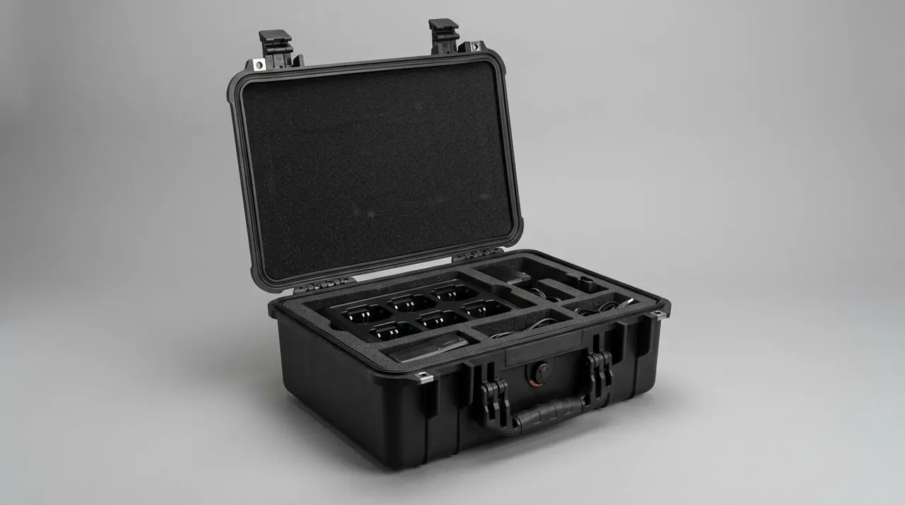
Lens and spare parts cavity design points. Provide a dedicated clean cavity physically separated from tool and consumable cavities. Use dedicated clean boxes so lenses go into a box before entering the cavity and never contact the insert directly. Position desiccant inside the clean cavity without touching protected items. Number each cavity with the corresponding part name and number for easy on-site counting and reassembly. Custom machining processes and capability are described in EVA foam insert custom process and Custom foam inserts guide.
Accessory and cable cavity design points. Provide a separate cavity for the delivery fibre with controlled bend radius, capped end faces and no shared cavity with heavy components. Control the coil radius of cooling lines and protect their fittings. Keep tools and consumables strictly separate from the optical cavity. Provide a separate dry document cavity so that documents do not fail from moisture.
| Cavity type | Contents | Key design parameters | Prohibitions |
|---|---|---|---|
| --- | --- | --- | --- |
| Laser source main cavity | Laser source body | Multi-point surface support, lateral stops, adjustable top clamp | No single-point support, no clamping on output window or interfaces |
| Optical head cavity | Cutting head assembly | Profile fit, guard, fitting and drawer limits | No storage cavity above |
| Optical clean cavity | Collimating, focusing, protective lenses | Dedicated clean boxes, low-outgassing material, desiccant | No sharing with tools or consumables |
| Fibre cavity | Output delivery fibre | Controlled radius, end caps, independent fixation | No small-radius bends, no compression |
| Accessory cavity | Cooling lines, cables, sensors | Controlled coil radius, fitting caps | No connection to the optical cavity |
| Document cavity | Manuals, calibration and test documents | Independently sealed, moisture protected, fixed position | No mixing with consumables |
11. Transport Testing: ISTA, GB/T 4857 and ASTM D4169
The effectiveness of a packaging scheme must be verified by citable standard testing rather than judgement.
The ISTA series is graded by transport form and weight: Series 1 covers non-simulation performance tests, Series 2 partial simulation, Series 3 general simulation including temperature and humidity conditioning, and Series 6 carrier-specific and e-commerce programmes. For single laser source or optical head cases, ISTA 2A suits partial simulation of a single package; for palletised machine case sets, ISTA 3E is closer to reality; and for export cargo with temperature and humidity requirements, the conditioning steps of ISTA Series 3 are more complete. The process is described in ISTA transport testing procedure.
The GB/T 4857 series is the Chinese family of basic test methods for transport packages, covering vibration, shock, stacking and drop. For laser equipment cases three matter most. The vibration test evaluates internal displacement and fastener loosening risk, and after the test the beam path and fastener state should be checked. The stacking test evaluates structural stability under warehouse and container stacking, and laser equipment cases normally do not permit heavy stacking, which must be clearly marked. The drop test evaluates the integrity of case and contents in an accidental drop. The method is analysed in GB/T 4857 transport packaging testing.
ASTM D4169 combines distribution cycles with assurance levels to build a test sequence and suits sea freight and intermodal transport. It is described in ASTM D4169 distribution cycle testing.
| System | Emphasis | Typical laser equipment scenario | Common procedures |
|---|---|---|---|
| --- | --- | --- | --- |
| ISTA | General simulation and carrier specific | Export machine case sets, palletised dispatch | 3E, 3A, 2A |
| GB/T 4857 | Domestic road and rail | Domestic integrator and customer site delivery | Vibration, stacking, drop series |
| ASTM D4169 | Intermodal distribution cycle | Overseas projects, sea and land combined | DC12, DC13 and similar |
Additional verification items beyond standard testing:
- Isolation effectiveness verification. Place accelerometers at critical positions inside the case, such as the laser source base and the optical head cavity, run the test to the actual transport route or a standard vibration spectrum, record the transmissibility curve and confirm there is no significant amplification in the frequency bands of concern.
- Shock recording verification. Place impact indicator labels that record whether a set threshold was exceeded, plus a transport data logger, and collect data on real shipments to iterate the insert design. For laser equipment this is the single most practical verification tool.
- Optical cleanliness verification. Place cleanliness witness plates inside the clean cavity, ship under real conditions and count settled particles afterwards to assess the effectiveness of the clean packaging.
- Humidity verification. Place a temperature and humidity logger inside the cavity, record the humidity profile of the whole journey, confirm it stays within the allowable range for optics and inspect desiccant consumption.
- Reassembly verification. Simulate the on-site workflow, record the time and problems from unpacking through to completed reassembly, and use the results to optimise cavity order and labelling.
Where a customer asks to reference MIL-STD-810H, it may be used as an environmental test method basis for designing test conditions such as high-temperature storage, low-temperature storage, damp heat cycling, vibration endurance and transport drop. It must be made clear that the standard is a test method standard and not equivalent to military certification, and no military certification claim may be made. Related compliance notes are in MIL-STD-810H as an environmental test basis.
12. Marking, Documentation and On-Board Spare Management
Marking and documentation are part of delivery completeness, and that matters especially for optical equipment.
Recommended external markings:
- Equipment information: equipment name and model, serial number, production batch, net and gross weight, external dimensions.
- Handling pictograms: this way up, keep dry, do not stack, do not roll, centre of gravity, lifting points, following general practice in the GB/T 191 package handling pictogram and GB/T 6388 transport package marking systems.
- Laser safety marking: retain the laser warning label as required, in a visible position that is not obscured.
- Impact indicator labels: fixed conspicuously on the outside so that an over-limit shock can be judged visually on arrival.
- Traceability code: a QR or barcode linking equipment number, inspection records, packing list and arrival record.
- Unpacking notice position: stating the environment requirements for opening, such as clean, dust-free and no grinding or cutting work nearby.
Recommended accompanying documentation:
- Packing list: item by item, with part name, model, quantity and cavity number.
- Laser safety and operating documents: safety manual, operating manual and spare warning labels.
- Quality and test documents: factory inspection report, certificate of conformity, and any agreed type test or third-party test report.
- Isolation and shock data: where required, isolation test data and the initial state record of the impact indicator labels.
- Document storage: documents must be protected from moisture, contamination and compression, ideally in a sealed document pouch on the outside of the case or in a dry document cavity inside, isolated from the optical cavity.
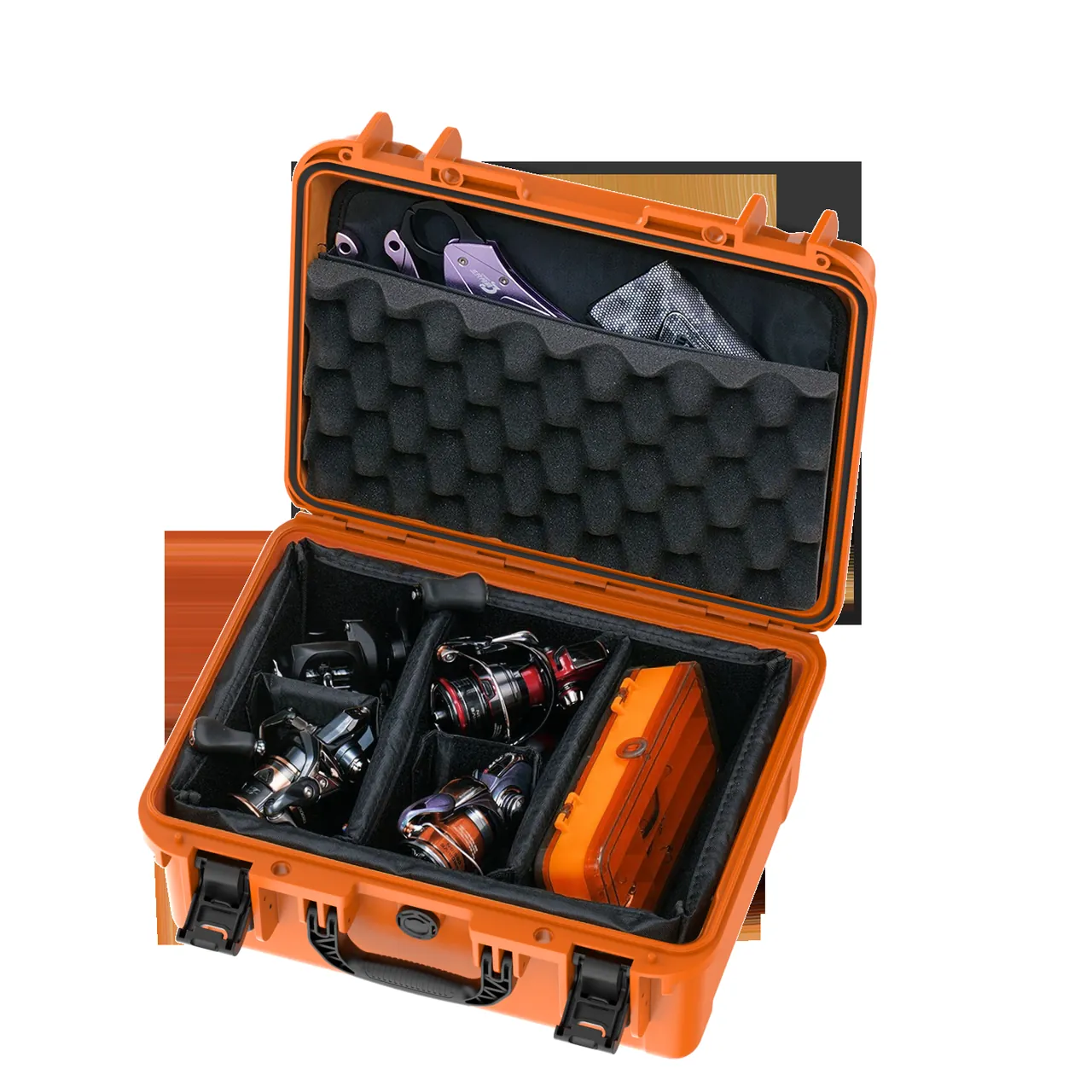
On-board spares and consumables management. A laser cutting machine usually ships with protective lenses, nozzles, seals and filters. Management points are dedicated cavities so spares never mix with the machine body or optics; clean packaging, mandatory for optical spares; easy counting, with cavity labels showing name and quantity; and no mixing with tools, since the metal particles tools generate are a contaminant source for optics.
13. Procurement Acceptance, AQL and Specification Selection Table
When buying laser cutting machine cases in volume, acceptance criteria must be written into the contract. The acceptance focus for this type of case is isolation effectiveness, cleanliness control, sealing reliability and structural strength.
Recommended incoming inspection items:
- Appearance and dimensions: external dimensions and insert cavity dimensions match the drawing; no cracks, sink marks or flash on the case; sealing face flat.
- Sealing performance: sample check to the agreed class, for example an air-tightness or water-tightness test; continuous perimeter seal fit check; confirmation that the gasket is replaceable.
- Structural strength: sample static load test at the rated load multiple held for the specified time, confirming no permanent deformation or cracking; sample corner drop or simulated drop.
- Insert fit: trial assembly with the actual item or a gauge, confirming no interference, no point contact and smooth removal; for the optical cavity, confirm the insert material contains no hard fillers and presents no scratch risk.
- Cleanliness check: visual inspection of the optical cavity for particles, fibre and odour; obtain outgassing or cleanliness documentation for the insert material.
- Desiccant and humidity measures: check desiccant type, quantity and placement; confirm the humidity indicator card is provided.
- Pressure equalisation valve: functional check that it breathes under differential pressure while blocking liquid water and particles.
- Marking and documentation: content, position and durability of markings; completeness of accompanying documents; document cavity sealing effective.
AQL sampling method. Sample size and acceptance criteria follow batch size, inspection level and AQL value. For laser equipment cases the recommendation is a tighter AQL for critical defects such as seal failure, an insert that puts optical components in contact with hard material, structural cracking, a non-functioning pressure equalisation valve, or a cavity dimension error that prevents assembly, and a looser AQL for minor defects such as colour variation, light flow marks or font differences in markings. The method and sampling tables are set out in Custom case acceptance and AQL.
Specification selection table:
| Cargo category | Recommended case type | Insert and protection scheme | Sealing class recommendation | Suggested transport testing |
|---|---|---|---|---|
| --- | --- | --- | --- | --- |
| CO2 laser | Heavy-duty isolating case | Axial multi-point support, attitude fixation, dry sealed window | IP65 | ISTA 2A plus vibration plus shock recording |
| Fibre laser | Heavy-duty isolating case | Graded isolation, dedicated fibre cavity, end caps | IP65/IP67 | ISTA 3E plus vibration plus humidity verification |
| Solid-state and ultrafast laser | High-grade isolating case | High-grade isolation, thermal buffer, impact indicators | IP67 | ISTA 3E plus temperature and humidity cycling |
| Optical head and cutting head | Clean cavity case | Profile fit, guard, drawer limit, clean cavity | IP67 | ISTA 2A plus cleanliness verification |
| Lenses and spares | Clean box plus dedicated cavity | Dedicated clean boxes, low-outgassing material, desiccant | IP67 | ISTA 2A plus cleanliness witness plates |
| Output delivery fibre | Dedicated fibre cavity | Controlled radius, end caps, independent fixation | IP65 | ISTA 2A plus bend radius review |
| Accessories and consumables | Separated cavity case | Separated fixation, surface protection, fitting caps | IP65 | ISTA 2A plus appearance inspection |
JUNZHJIA provides complete custom delivery capability in laser processing and optical communications equipment: developing cases and inserts to laser source and optical head specifications, grading isolation and location by component sensitivity, matching low-outgassing insert materials to cleanliness requirements, configuring pressure equalisation valves and replaceable gaskets to sealing needs, reserving marking and document positions for export requirements, and supplying OEM/ODM manufacturing with stable volume delivery. Kexin New Materials (Guangdong) Co., Ltd. operates a complete chain from structural design, tooling development and rotomoulding or injection moulding through insert machining and case assembly, serving laser equipment manufacturers, integrators, service providers and rental companies. For a first engagement we recommend a small trial batch and physical trial assembly including isolation and cleanliness verification, moving to volume supply once verified. Partner evaluation points are covered in How to choose a case OEM factory.
14. Export, Storage and On-Site Reassembly Points
Four points for export:
- Moisture and condensation are the primary risk. Sea freight containers crossing climate zones produce condensation, and heat accelerates coating degradation. A sealing class of IP67 or above is recommended, with a pressure equalisation valve and a calculated desiccant quantity, plus a temperature and humidity logger inside for arrival verification. Where required, the test plan can follow an ASTM D4169 distribution cycle.
- Structural strength for repeated handling. Export cargo passes through factory loading, port storage, vessel loading, discharge and inland transport. The scheme should be designed for a more severe distribution cycle, with case corners, lifting points and the base structure reinforced, and single-use inserts avoided.
- Regulations and documentation. Cross-border transport involves different national import, label language and documentation requirements. Laser product safety labels and manuals must travel complete with the goods and must not be lost during transhipment. Country-specific requirements should be checked at quotation stage.
- Stacking and attitude. Laser equipment cases normally must not carry load on top and must be clearly marked do not stack on both case and documentation. Where stacking is unavoidable, it must be carried by a dedicated pallet and rigid frame rather than by the case itself.
Four points for storage:
- Temperature and humidity control. Store in a temperature-stable, humidity-controlled area, away from heat sources, windows and external walls where temperature swings are large, and not directly on the floor where damp rises.
- Desiccant management. Replace the desiccant after every opening, check the humidity indicator card periodically and keep a replacement log. In long-term storage this is the most frequently neglected task with the most direct consequences.
- Attitude and stacking. Store in the marked attitude, do not place other cargo on top, and place heavy equipment cases on low racking.
- Reusable case maintenance. Establish an inspection routine for reusable cases: after each return, check gasket condition, whether the insert is damaged or deformed, whether cavities retain particles, whether desiccant needs replacing and whether the pressure equalisation valve is clear. Evaluation methods are in Protective case service life evaluation and cleaning methods in How to clean a protective case.
Five points for on-site reassembly:
- Environment preparation. Choose a clean, dust-free area with no grinding or cutting work for unpacking and reassembly, lay out a clean bench and prepare clean gloves and necessary cleaning consumables.
- Removal in sequence. Take components out in the order given by the packing list and cavity labels, keep major components packaged until they reach the installation station, and unwrap optics only immediately before fitting.
- Reassembly checks. Check housing and interfaces for impact damage, nozzle and ceramic ring for deformation, fibre end faces for contamination and fasteners for loosening, and confirm the state of the impact indicator labels.
- Pre-power checks. Complete the installation checks required by the equipment manufacturer before energising. Laser emission must only be initiated by qualified personnel working to applicable safety requirements.
- Case and insert disposition. Where the customer keeps the case for a later move, return the insert to its original cavity layout, replace the desiccant, clean the sealing face and store sealed; check gasket condition and insert deformation before the next use.
On the reuse value of the transport case. Laser cutting machines are frequently relocated, rotated through rental fleets and shipped to exhibitions, and a well-designed reusable case can serve several times across the life of the equipment, delivering far more value than single-use packaging. Procurement should therefore consider gasket replaceability, insert replaceability, structural repairability and spare parts supply from the outset, discussed further in Protective case service life evaluation. JUNZHJIA can develop a standardised case platform around a customer equipment series, combining a shared case structure with replaceable insert modules to balance commonality and customisation and reduce packaging management complexity across multiple models.
Frequently Asked Questions
Q: What is the biggest difference between a laser cutting machine case and an ordinary equipment case? A: The biggest difference is that one machine contains two component classes with completely different protection logic, and they must be handled in separate zones. The laser source is a heavy energy source whose protection focuses on limiting the shock acceleration and vibration transmitted to the body, maintaining installation attitude and preventing internal optic displacement. The optical head is a precision optical assembly whose protection focuses on clean enclosure, axial location and preventing coating moisture attack and scratching. Their load magnitudes may differ by two orders of magnitude, and if they share a cavity the inertial load of the heavy part crushes the cushion layer and strikes the optics directly. A laser cutting machine case must therefore deliver graded isolation, physical zoning and clean humidity control: cushioning and location designed by component sensitivity level, physical separation of the optical cavity from tool, consumable and fibre cavities, and IP67 sealing with desiccant and a pressure equalisation valve. These cases also usually need to support on-site reassembly and a second move, so reusability and replaceable gaskets and inserts are further differences. Q: What does a laser source fear most in transit, and how do you tell whether it was damaged? A: What a laser source fears most is internal optic displacement caused by shock and sustained vibration. What makes this awkward is that it usually leaves no visible trace, appearing instead at the cutting end as a rough cut face, dross, a widened kerf, an unstable focus and process parameters that cannot be reproduced. There are three levels of assessment. First, transport records: place impact indicator labels and a transport data logger inside the case, and read the data on arrival to judge whether the set acceleration threshold was exceeded. Second, arrival inspection: check the housing, interfaces, output window, fasteners and cooling fittings for impact deformation or loosening. Third, post-installation optical and process verification: follow the equipment manufacturer check procedure to verify output power, beam quality and focal position, then confirm by test cutting whether process parameters can be reproduced. Risk reduction belongs at the design stage: select cushion material and bearing area to the manufacturer acceleration limit, apply multi-axis location to constrain degrees of freedom, avoid low-frequency resonance amplification, and use a data logger on real shipments to iterate the insert design. Q: Why can lenses inside an optical head not travel in the same case as tools and consumables? A: Because tools and consumables generate large amounts of particulate in transit, and particles are a lethal contaminant for optical coatings. Wrenches, nozzles, abrasives and metal spares rub against each other under vibration and generate metal and abrasive dust; cartons, paper labels and fibrous packaging release fibre and paper debris; in transit these particles migrate freely inside the case and settle on lens surfaces. The consequence is that under high-power laser irradiation a settled particle absorbs energy, is heated and ablated in an instant, and creates a permanent damage site in the coating, increasing scattering and reducing transmission, which ultimately shows as insufficient output power and degraded cutting. In addition, general packaging foams and some plastics continuously release condensable volatiles such as siloxanes and plasticisers, which accumulate inside a sealed case and deposit as a haze on lens surfaces that is harder to remove than particles. The right approach is to place lenses in dedicated clean boxes, physically separate the lens cavity from tool, consumable and spare cavities, and choose insert materials that are low-outgassing, low-shedding and free of hard fillers, and on site to prefer replacing the protective lens over repeatedly cleaning the focusing lens. Q: What specific measures protect a laser machine shipped by sea freight from moisture? A: Use a combination of five layers. Layer one, sealing: a case sealing class of IP67 or above, a continuous closed-loop perimeter gasket, groove depth and width tolerances matched to the gasket cross-section, and multiple latches so the sealing face is evenly loaded. Layer two, desiccant: quantity calculated from free internal volume, packaging material moisture vapour transmission rate, transport duration and target humidity with an allowance added; the recommended storage humidity for optics is typically below 50 percent RH and the specific limit should come from the equipment manufacturer; indicating types make visual checking easier. Layer three, pressure equalisation valve: a high sealing class creates a pressure differential across altitude changes and air freight, and the valve breathes slowly while a hydrophobic and oleophobic membrane blocks liquid water and particles. Layer four, thermal buffering: the thermal inertia of the case delays temperature change so the cargo surface lags the environment and the condensation window shrinks. Layer five, process management: pack in a low-humidity environment, avoid moving directly from a cold store into hot humid air, let the case equalise in temperature before opening, and place a temperature and humidity logger inside for arrival verification. Q: How do you judge whether the isolation design of an optical equipment case is adequate? A: Judge from four angles. First, is the cushion material matched to component weight? This is the most common source of error: a material that is too soft compresses fully under a heavy load and loses its cushion stroke, letting the component strike the case wall, while a material that is too hard cannot absorb energy and transmits shock almost unchanged. Correct practice is to select material hardness and bearing area from cushion curves using component weight, the allowable acceleration limit given by the manufacturer and the expected drop height. Second, are all degrees of freedom constrained? Filling gaps alone cannot limit vertical bounce, horizontal translation, rotation about a horizontal axis and rotation about the vertical axis; a structured combination of base support, lateral stops and adjustable top clamping is required. Third, has low-frequency vibration been assessed? Road transport energy concentrates at low frequency, and if the system natural frequency falls in that band, resonance amplifies; this needs a lower natural frequency, added damping and multi-axis constraint. Fourth, is there measured data? Accelerometers at critical positions recording transmissibility in a vibration test, or a transport data logger on real shipments, is the only reliable verification. Q: What sealing class does a laser cutting machine case need? A: IP67 is recommended, under IEC 60529 and its Chinese counterpart GB/T 4208. The reason is that optical coatings are moisture-sensitive: multilayer dielectric stacks undergo hydrolysis, interfacial delamination and mould under prolonged high humidity, and condensation in a sea freight container crossing climate zones does still more damage. IP67 is dust-tight and protects against harmful ingress of water under temporary immersion, which suits long-distance transport and storage. Three boundaries must be stated clearly. First, the IP class describes the case resistance to water and particles and does not indicate the humidity level inside; if the case is sealed with humid internal air, that humidity persists, and lowering it requires desiccant and low-humidity packing. Second, the IP class says nothing about vibration isolation; the two are independent parameters and must be designed and verified separately. Third, the IP class is not laser safety protection; a sealed case offers no laser radiation protection. For short domestic transfers in a controlled environment IP65 is often sufficient, and where hosing or heavy spray occurs IP66 may be considered. Gaskets should be replaceable, and replacement intervals and spare supply should be agreed in the contract. Q: What is easily overlooked during on-site reassembly? A: Five things matter and are often missed. First, the unpacking environment. No packaging can compensate for leaving equipment open for hours in a dusty area, so choose a clean, dust-free location with no grinding or cutting work, lay out a clean bench and prepare clean gloves. Second, removal sequence. Take components out in the order given by the packing list and cavity labels, keep major components packaged until they reach the installation station, and unwrap optics only immediately before fitting so they are not exposed mid-process. Third, reassembly checks. These cover housing and interface impact damage, nozzle and ceramic ring deformation, fibre end face contamination, fastener loosening, and the state of the impact indicator labels, all before energising. Fourth, the compliance precondition before power-up. Laser emission must only be initiated by qualified personnel working to applicable laser safety requirements; the transport case is not a laser safety guard of any kind. Fifth, case and insert disposition. Where the case is kept for a later move or second transfer, return the insert to its original cavity layout, replace the desiccant, clean the sealing face and store sealed, then check gasket condition and insert deformation before the next use. Q: Why do laser cutting machine cases usually carry a do-not-stack marking? A: Because the design objective differs from ordinary industrial packaging. Conventional industrial packaging is designed around stacking load, but the interior of a laser cutting machine case is a graded isolation structure: cushion materials are selected to component weight and allowable acceleration limits, and their load capacity is designed to absorb shock, not to carry sustained static load. If cargo is stacked on top, the static load continuously compresses the cushion layer, which loses its stroke and elasticity while transmitting pressure into the laser source body and optical head, potentially causing internal optic displacement, lens compression or housing deformation. Uneven load distribution can also collapse part of the insert and deform the case lid, breaking the seal. Where stacking really is required, the correct approach is to carry the load through a dedicated pallet and rigid frame so the case itself bears nothing from above, and to state the stacking limit and attitude requirement clearly on the case and in the accompanying documentation. Attitude and stacking requirements can follow general practice in transport package handling pictogram markings.
Conclusion & Related Reading
The design core of a laser cutting machine case is recognising that one machine contains two conflicting protection logics and satisfying both through zoning, grading and separation. For the laser source, what must be protected is the positional datum of the internal optical structure: limit the acceleration and vibration transmitted to the body through graded isolation, constrain all degrees of freedom through multi-point surface support underneath, lateral stops and adjustable top clamping, and iterate the design using shock records and measured data. For the optical head and lenses, what must be protected is an extremely thin coating and its axial position: prevent particle and organic vapour contamination through clean packaging, low-outgassing insert materials and physical cavity isolation, prevent compression and displacement through profile-matched support and dedicated cavities, and control humidity and condensation through sealing, desiccant and a pressure equalisation valve. The thread connecting the two is material compatibility and cleanliness: every insert material that touches optics or shares a sealed volume with them must be evaluated for outgassing and particle shedding and verified under actual use conditions.
For laser equipment manufacturers, integrators, service providers and rental companies, the sensible sequence is: first grade by component type and sensitivity, classifying laser sources by type, optical heads by structure and lenses by coating requirement; then determine the isolation scheme, location method, sealing class and cleanliness measures for each level; then develop inserts for the main models and carry out physical trial assembly, including confirming that optics never contact hard material; then verify vibration, stacking and drop to ISTA, GB/T 4857 or ASTM D4169, using shock and temperature-humidity loggers on real shipments to collect data; and finally write acceptance criteria, marking systems, document lists and reassembly requirements into the delivery process. JUNZHJIA supports the whole path from structural design and isolation and clean insert development through trial samples to volume supply, with Kexin New Materials (Guangdong) Co., Ltd. manufacturing and delivering to customer equipment specifications and optical requirements, so that a laser cutting machine retains usable optical performance and process consistency from factory dispatch, storage and transport through to on-site reassembly. Note that the laser safety content here is included only to explain the management boundary in transport and delivery: the operation, commissioning and servicing of laser equipment must be performed by qualified personnel in accordance with applicable regulations, standards and company procedures.
Related Reading