

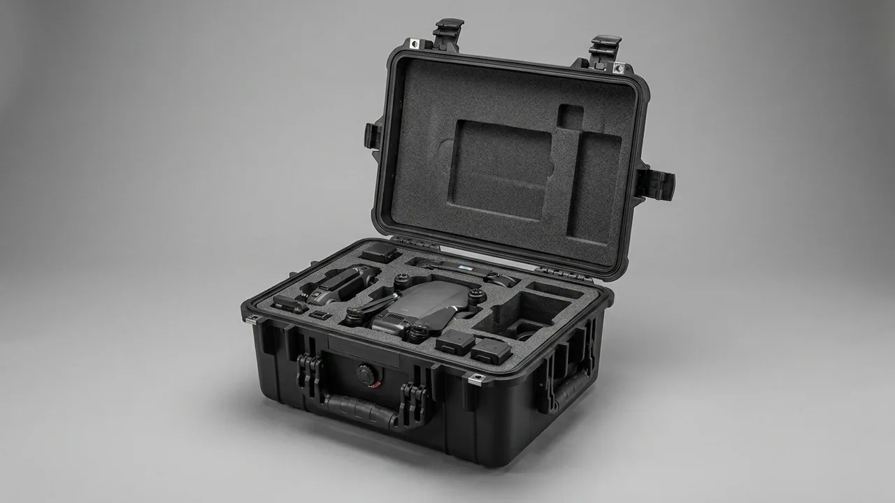
The value of a CNC machine tool is concentrated in a handful of surfaces measured in microns. The spindle taper and face set tool position and repeat tool-change accuracy. The guideway raceway and carriage set the straightness of every axis. The ball screw groove sets positioning accuracy and backlash. The scale body and scanning head of the optical encoder set the truthfulness of full-closed-loop feedback. Not one of these surfaces can be restored on site by welding, grinding or hand scraping. The conclusion JUNZHIJIA puts forward is that the transport protection of CNC machine tool components has to be designed component by component according to the nature of each fitted surface, and graded accordingly. A spindle travels supported on its flange joint face, with a protective sleeve always fitted into the BT or HSK taper and with neither taper nor face carrying load. A linear guideway allows only soft half-round cradles to touch the raceway and keeps its carriages riding on the rail. A ball screw is supported at multiple equal-height soft points to control bending, and stays covered against particles throughout. Optical scales and similar metrology items are locked with their transport blocks and placed in the thickest cushioning zone. Case hardware is upgraded in material and isolated against galvanic corrosion in the GB/T 10125 salt fog context. Laying a spindle flat on timber baulks, slinging a guideway with bare wire rope, letting a ball screw overhang at one end, and shipping an optical scale in the same compartment as a heavy casting are the four most common errors made by machine builders and spares stores.
A machining centre or turning centre is normally built in one plant, inspected for accuracy, then partly dismantled and shipped as separate structural and functional groups to an assembly line or an end user. On the way it passes through in-plant transfers, yard storage, road legs and container shipping with repeated handling. The damage is deceptive because nothing is visible on arrival. A pressed mark in a guideway raceway only becomes noise and accuracy drift after assembly. A micron-scale high spot on a spindle taper only shows up as out-of-tolerance repeat tool-change position. A slightly bent ball screw only reveals itself as a taper error when a long workpiece is machined. A shifted scanning head on an optical scale triggers an alarm and stops the machine. Repairing these defects costs far more than preventing them, and the resulting disputes usually land inside the warranty period. This article sets out cradle structures, cushioning parameters, attitude requirements, corrosion practice and acceptance clauses by component category, for assembly and logistics departments at machine builders, dealer spares stores, and equipment engineering teams at precision machining companies.
Table of Contents
- Transport Failure Modes and Protection Boundaries for CNC Machine Tool Parts
- No-Impact Protection of the Spindle Taper and Face: How BT and HSK Differ
- Vibration and Attitude Control for Motor Spindles and Spindle Bearings
- Protecting the Precision Surfaces of Linear Guideways and Carriages
- Ball Screws: Bend Prevention, Contamination Control and Axial Restraint
- Optical Scales and Encoders: Vibration and Contamination Protection
- Tool Magazine, Tool Holders and Pull Studs as a Matched Set
- Machined Surface Corrosion Control: From Coating to Galvanic Isolation
- Case Structure, Sealing Grade and Pressure Equalization Valve
- Cushioning Liner Selection and Drop Verification
- Humidity, Condensation and Desiccant Configuration
- Transport Testing, Arrival Acceptance and Liability Records
- Marking and the On-Site Unpacking Sequence
- Frequently Asked Questions
- Conclusion and Further Reading
Transport Failure Modes and Protection Boundaries for CNC Machine Tool Parts
Grouping feedback from machine builder assembly lines, dealer spares stores and end user sites, transport damage to CNC machine tool components falls into four classes. The first is impact damage to fitted surfaces: a high spot knocked into a taper, a bright score across a face, a dent in a guideway raceway, a gouge across a ball screw groove. The damage scale is often in the micron range, visually unremarkable, yet it directly destroys positioning and transmission accuracy. The second is structural distortion: slender ball screws and long guideways deflect under self weight and vibration and retain permanent bend once the limit is passed, while bed and column castings can twist under single point lifting or eccentric stacking and then need levelling and geometric re-alignment on installation. The third is fretting and vibration damage: spindle bearings develop false brinelling while stationary under sustained vibration, motor spindle rotors shift relative to their encoders, and optical scale scanning heads slide relative to the scale body. The fourth is corrosion and contamination: flash rust on ground and hand-scraped surfaces, chips and cast iron particles entering raceways and acting as lapping compound, and seals ageing under heat and humidity.
What these four classes share is that they do not declare themselves on arrival, only after assembly, and cannot be repaired on site. The protection boundary therefore has to be fixed in writing before packing: the supporting face of each item, the materials allowed to touch it, the prohibited actions and the arrival inspection points. The table below pairs the failure focus of each major component group with its protection action, and serves as the index for the chapters that follow.
| Component group | Primary failure mode | Item protection action | Support and restraint | Process indicator (typical) |
|---|---|---|---|---|
| --- | --- | --- | --- | --- |
| Spindle with BT or HSK taper interface | Taper high spot, face score, pull stud bore damage | Taper sleeve, ring face guard, bore plugs | Flange joint face carries load, axis vertical | Taper contact check matches factory record |
| Motor spindle assembly | Bearing marks, internal encoder shift | Keep original packaging and factory attitude | Vertical restraint, even cushioning all round | Free rotation, no abnormal noise |
| Spindle bearing set | Loss of preload, raceway marks | Pairing numbers and spacers stay together | Inner ring or housing carries load, outer ring unloaded | Pairing numbers complete, no corrosion |
| Linear guideway pair | Raceway dents, carriage ball loss | Carriage stays on rail, end caps fitted | Multi-point equal-height support, no hard contact on raceway | Carriage resistance matches factory feel |
| Ball screw pair | Bending, groove gouging, return unit damage | Thread section covered, nut never left free | Cradles at diameter multiples along length | Full-length straightness within factory value |
| Optical scale and head | Scale score, scanning head displacement | Original packaging, transport locking block refitted | Separate compartment, thickest cushioning zone | Locking block position traceable |
| Tool holders and magazine parts | Taper to taper contact, grip groove damage | Individual pockets, cutting edge guards | Vertical insertion, holders never touching | No bright marks on taper, stud threads intact |
| Bed, column and other castings | Flash rust on machined faces, scraped face corrosion | Rust preventive oil plus rust preventive paper | Steel frame or timber cradles at equal height | No corrosion across scraped contact spots |
| Hydraulic and pneumatic parts | Rod scoring, seal ageing | Rod sleeves, port caps | Fixed in installation attitude, ports upward | Sealing faces free of visible scores |
No-Impact Protection of the Spindle Taper and Face: How BT and HSK Differ
The spindle is the accuracy datum of a CNC machine, and the protection logic depends first on which interface it carries. The 7:24 taper family, covering BT and JT tooling under the GB/T 10944 and ISO 7388 systems, achieves centring and torque transmission through friction on the taper surface. A high and even taper contact ratio is the foundation of accuracy, and the face plays essentially no locating role. Hollow taper shanks such as HSK, under the ISO 12164 system, use a short 1:10 taper combined with simultaneous face contact, so the taper and the face share both location and clamping duty. That difference dictates the shape of the transport guard. A 7:24 interface only needs the taper protected and the face tolerates a little clearance. An HSK interface needs a sleeve on the taper and a ring guard on the face at the same time, with the ring applying no concentrated load, because a locally compressed face lifts the taper off its seat and collapses the dual contact.
Practice divides into three layers. The first is the close-fitting sleeve: the sleeve outer taper matches the spindle bore to limit movement, the inner surface is a soft material, and the outer end carries a handle for easy removal. Never plug a taper with cloth or cardboard. Such fillers neither restrain movement nor keep fibres and abrasive particles off the surface, and under vibration they score it. The second layer covers the face and the pull stud bores: a ring guard profiled to the face, with relief grooves so that handling does not create a suction seal, plus soft plugs in every pull stud and threaded bore. Blow out chips before fitting the plugs, because debris left in a bore acts as lapping compound once vibration starts. The third layer is attitude and support: the spindle should sit on its flange joint face or on the spindle housing locating face, with the axis vertical so gravity travels along the axis rather than producing a lateral component on the taper. Using the taper or the face as a supporting surface is prohibited, and so is leaving a spindle lying flat for any length of time, since the taper rim and the face edge then become load points in a direction the design never intended, which is the fastest route to a high spot or a rolled edge.
A distinction matters here between a spindle body and a motor spindle assembly. A spindle body is a rigid item that can be dismantled and inspected, whereas a motor spindle integrates shaft, bearings, rotor and encoder inside one housing. Field teams cannot strip it, so transport damage typically appears only after power-up as excessive vibration or an encoder alarm. The protection emphasis for a motor spindle therefore falls on attitude and vibration control, and the handling of bearing preload and overall attitude described in Spindle and Motor Spindle Cases applies, since both follow the same principle of shipping the assembly as a metrology-grade rigid body.
On arrival, taper contact is normally checked with red lead or blue marking compound, and common industry practice is to require contact spots evenly distributed with the contact ratio at the agreed value, with higher requirements on critical and high-speed machines. The face is checked with a straight edge and feeler gauge for flatness and contact pattern. Acceptance clauses should state that taper and face contact results match the factory record rather than simply saying there is no visible damage, because visual inspection cannot find a micron-scale high spot while a contact check quantifies it.
Vibration and Attitude Control for Motor Spindles and Spindle Bearings
The transport damage mechanism of spindle bearings has nothing to do with ordinary wear. When a stationary bearing is exposed to sustained vibration, the contact points between rolling elements and raceways undergo repeated micro-sliding, the lubricant film breaks down locally, and the metal surfaces cold weld and tear, leaving indentations spaced at the rolling element pitch. This is false brinelling. Depth is usually in the micron range and neither visual inspection nor touch reveals it, yet at service speed it appears as periodic noise and progresses to spalling in a short time. The protection priority is therefore not impact avoidance but micro-motion avoidance. Keep the original packaging and the factory rust preventive film, and do not unpack bearings to save space. Let the inner ring or the housing carry load so the outer ring sees no radial load in transit. Angular contact bearing sets used in pairs must stay together in the same sequence with their preload spacers, because once pairing is scrambled the preload must be re-measured, and that assembly time dwarfs the protection cost.
The attitude requirement for motor spindles comes from the internal distribution of media. In a spindle lubricated by oil mist or oil-air, the internal oilways and seals have a defined up and down orientation. Inverting or side-storing such a spindle for a long time lets lubricant migrate into the motor cavity and the encoder area, reducing insulation and disturbing signals. For a water-cooled spindle, coolant left undrained in a cold environment freezes and expands, pressing on internal channels. The packing attitude should therefore follow the factory packaging attitude exactly, with the liner contoured to the housing, cushioning even on all sides and do-not-invert marking on the case. If a motor spindle must travel with a tool holder fitted, the holder needs its own restraint rather than using the spindle taper as a load bearing face.
Vibration control targets should be derived backwards from the component allowance rather than judged only by whether the case survives a drop. Engineering practice applies two levels of verification. The first is the drop case, following the GB/T 4857 series or an ISTA procedure to establish drop height and then checking liner compression and transmitted acceleration. The second is random vibration, following GB/T 4857.23 or the ASTM D4169 assurance level over a long cycle to check whether the cushioning retains residual compression or shifts. A typical working target is to keep peak acceleration transmitted to the spindle below about 15 g with margin, but the actual figure must be calculated from spindle mass, permitted acceleration and liner compression characteristics rather than copied. Where a case also contains items with extreme rotational accuracy requirements, such as spindle test bars or ball plates, those items belong in their own compartment in the central zone of the case, away from walls and wheels, following the low-acceleration zone layout described for Metrology Standard Cases.
Protecting the Precision Surfaces of Linear Guideways and Carriages
Failures of a linear guideway pair almost always originate in the raceway. The rail raceway is a hardened ground surface, and the carriage contains a ball or roller recirculating chain with retainers. A single dent pressed into the raceway by a hard object shows up after assembly as fluctuating carriage resistance and noise, and develops into pitting and spalling over service life. A more common problem is a carriage sliding off the end of the rail in transit. Once a carriage leaves the rail, rollers drop out in rows, retainers deform, and the carriage is effectively scrap. The first rule on site is therefore that a carriage must never leave its rail. Where removal is unavoidable, a dummy rail must be butted to the rail end first, or a carriage protection sleeve fitted, so the recirculating chain stays closed, and both carriage ends must be capped.
The support arrangement decides whether a guideway is permanently bent in transit. A slender rail has a section moment of inertia far smaller in one direction than the other, so if it is supported only at both ends with a free middle section, self weight and vibration produce residual deflection about the weak axis. Practice is multi-point equal-height support. Cradle spacing is calculated from rail length and section moment of inertia, with a common working range of about 800 to 1200 mm between supports and end overhang kept within 300 mm. The height difference between support tops should stay within 1 mm, contact surfaces should be soft, and contact should fall on the mounting datum face or a non-machined side rather than on the raceway. Slinging a rail with bare wire rope is prohibited, because rope against a raceway edge is line contact at very high pressure that cuts a row of dents along the raceway. Stacking two rails so their raceways touch, or standing rails directly on a concrete floor or a steel rack, is equally unacceptable.
Corrosion and particle control cannot be skipped either. A ground raceway has no coating at all, so flash rust can appear within days in humid air, and rust products then become abrasive particles inside the raceway. Standard practice is to coat with a washable rust preventive oil and wrap in rust preventive paper, choosing an oil that a normal cleaner removes and that contains no chloride additives, so residue does not degrade the later grease. On arrival, compare carriage resistance against the factory feel and sample rail mounting face straightness with a laser interferometer or precision level against the factory inspection record. These same items act as core acceptance points for Linear Actuator Cases, because the accuracy of every linear motion device rests on that one directly measurable geometric quantity.

Ball Screws: Bend Prevention, Contamination Control and Axial Restraint
A ball screw is the component most likely to deform quietly in transit. Three risks dominate. The first is bending: a screw is slender, and once cradle spacing is too wide or heights are uneven, self-weight deflection plus vibration exceeds the allowance and leaves a permanent bend, which shows up after assembly as cumulative pitch error over full travel and increased backlash. The second is groove gouging: a gothic arch raceway is extremely sensitive to hard objects, and a single gouge makes the balls impact as they pass and accelerates raceway fatigue. The third is nut and return unit damage: balls circulate inside the nut through a return unit, so if the nut leaves the screw or takes an impact, balls scatter and the return unit deforms.
Support design follows four rules: multiple cradles, equal heights, soft contact, and never loading the thread groove. Cradle spacing can start from a working range of 30 to 40 times the nominal thread diameter, taking the lower end for slender or hollow screws, then be verified by modelling the screw as a simply supported beam and keeping maximum deflection within roughly one third of the total length tolerance, with design calculation governing. Height difference between cradle tops must stay within 1 mm, the cradle contact face should be a soft half-round form, and contact should be placed on the plain journal section or a shoulder, never on the thread groove with a hard V block. A V block looks stable but concentrates the entire load on two thread flanks and is the classic mistake. The nut has two acceptable dispositions: keep it threaded on the screw and locked with a transport block so it cannot travel axially, or remove it into a dedicated locating sleeve that keeps the recirculating chain closed while the nut is packed separately with its pairing recorded. Wrapping a nut in paper and dropping it loose into the case is prohibited, as is letting it slide freely along the screw, because long free travel contaminates the grease through micro-motion between balls and raceway.
Contamination control and axial restraint are companion actions. The threaded section and both nut ends should be covered with a dust boot or guard, and the covering material must not shed, which rules out cardboard, friable foam and chloride-containing film. The support journals and coupling interface at the screw ends need an additional soft wrap. Axially, a positive stop is required so the screw cannot slide and strike the case wall under braking, and the stop must bear on a shoulder or an end face step, never on the thread groove or a fitted journal. Where a screw, coupling and bearing housing form a matched assembly, shipping the group as a rigid body is preferable, with interface protection following the practice described for Shaft Coupling and Transmission Cases, namely keep the group assembled, guard the interfaces and restrain it axially.

Optical Scales and Encoders: Vibration and Contamination Protection
An optical scale is the feedback datum of a full-closed-loop CNC machine, and its construction makes it unusually sensitive to transport conditions. In a sealed scale the gap between the scale body and the scanning head is very small, so any action that creates relative movement or relative impact can score the scale or disturb the reading. In an open scale the grating surface is exposed, and oil, fingerprints and dust all corrupt the signal. The scale is also an electronic assembly, for which forces on the connector, electrostatic discharge and condensation are classic failure paths. Its protection is therefore a combination of mechanical locking, environmental isolation and static control.
Mechanical locking has a defined action list. Before packing, the scanning head must be locked to the scale body with the transport block or dedicated screws specified by the manufacturer, so the two cannot move relative to one another. The scale body travels in its original packaging form, never bent and never compressed. Interface cables are coiled and secured separately, with no bending load or free swinging at the connector root. Removing the transport blocks before installation is mandatory, and forgetting to do so and then powering up is a frequent human-caused failure that destroys the scale on contact. The case should therefore carry an unpacking checklist with photographs of the locking block positions, checked item by item on arrival. On attitude, a scale is a metrology item and belongs in the central zone of the case in the thickest cushioning layer, away from walls, wheels and lifting points, and never in the same compartment as a bed or column casting.
Environmental isolation matters just as much. Scale failures often begin with condensation, where a water film that forms on the cold surface overnight travels along the cable into the connector and causes insulation loss and signal drift. Desiccant and a humidity indicator card should therefore be included in the scale packaging, sized from the transport duration and the case sealing grade. The sealing arrangement has to be paired with pressure equalization, or the pressure difference created by temperature change will either lift the seal or pump moist air into the case, as described in Case Pressure Equalization Valve Configuration and IP Rating Selection. For static control, aluminium scale bodies and electronic modules should be wrapped in antistatic bags or antistatic liner material, and personnel should ground themselves when removing packaging to avoid electrostatic discharge damage in dry winter conditions.
Tool Magazine, Tool Holders and Pull Studs as a Matched Set
The taper and the grip groove of a tool holder are locating and clamping datum surfaces, and any bright mark, high spot or burr degrades tool change positioning and clamping force. The pull stud thread and the holder internal thread determine how reliably the tool is drawn into the spindle. Tool holders normally travel as a set: many pieces, each heavy, every surface finish-machined. The two most common problems are holders touching one another and holders having no defined pocket.
Practice is to provide an individual liner pocket for each tool position number, so every holder stands on its own, separated by soft dividers. Holders travel vertically, with orientation consistent, and in no case should a taper become a load bearing face. Cutting edges and long overhang tools such as boring bars, broaches and inserted cutters need edge guards with a soft inner layer, and long overhang shanks need an intermediate support so they cannot bend under vibration. Pull stud threads and internal threads receive soft plugs that are easy to remove and that leave no debris in the thread. Tool magazine sub-assemblies, including chain and slide of a chain magazine, the indexing mechanism of an umbrella magazine and cam mechanisms, travel as rigid bodies bolted to dedicated pallets, with chains and cams never carrying hanging load, and rotating parts locked or braced. The last step in set management is documentation: a tool list, a pocket numbering drawing and pairing records inside the case, with machine model and serial number marked outside, because holder geometry across one machine series is nearly identical and without number binding mis-assembly on the line is almost guaranteed.
Machined Surface Corrosion Control: From Coating to Galvanic Isolation
Beds, columns, tables and saddles in a CNC machine are usually cast iron, and their machined surfaces include ground faces, hand-scraped faces and milled joint faces. Cast iron corrodes quickly in humid air, and a hand-scraped face carries the contact spots created by scraping, so once corrosion pits appear the contact ratio and rigidity cannot be recovered by simple grinding and the surface must be scraped again. Protection therefore has three layers, coating, material and verification, and losing any one of them allows failure over a long sea voyage.
At the coating layer, every exposed machined face receives a washable rust preventive oil in an even film, and hand-scraped faces take rust preventive paper pressed on over the oil film with no air pockets, held at corners by soft guards. Two rules govern oil choice: it must be fully removable with normal cleaners so it cannot contaminate assembly or later painting, and it must contain no chloride type extreme pressure additives, since chloride residue is a hazard for both steel and non-ferrous surfaces. At the material layer, exposed case hardware should be 316 or 316L stainless steel, carbon steel parts should be zinc plated and passivated and must not touch stainless directly, aluminium frames and profiles should be anodised with insulating washers breaking the galvanic path, and fasteners should be A4-70 or better. At the structural and verification layer, the case must not retain water, the base needs a raised, drained structure, and desiccant is sized by internal volume and transport days. Verification uses neutral salt fog testing to GB/T 10125 on case hardware, latches and hinges. For short transport cycles, 96 hours with the criterion that no functional corrosion appears and latches and hinges still operate is a reasonable functional threshold, while cycles beyond three months or long storage on an island site justify a longer duration or a tightened agreed protocol. Hinges and latches collect salt and dust more than any other feature, and their construction and corrosion measures follow the general practice in Hinge, Latch and Seal Construction, with heavy machine cases stepping the material grade up one level across the board.
Case Structure, Sealing Grade and Pressure Equalization Valve
Case selection for CNC machine tool components depends on individual weight and centre of gravity position. Small and medium precision items such as spindles, tool holders, optical scales and servo motors suit modified PP or ABS injection moulded cases with a compartmented liner for set transport, while heavy castings such as beds, columns and saddles need rotationally moulded LLDPE cases or steel frame composite structures, with internal load beams carrying weight directly into the case corners so the base cannot deform locally under full load. Reinforced corners, handles and wheels must follow the same load path as the internal restraint points, otherwise case wall deflection during lifting is transmitted into the component.
Sealing grade follows the exposure profile. IP65 as defined by IEC 60529 and GB/T 4208 suits yards and deck transfers with spray risk, while IP67 suits short immersion or long humid sea freight. A higher sealing grade, however, amplifies the pressure difference created by temperature change: internal pressure rises on a hot day and lifts the seal, and a partial vacuum forms on a cold night and draws moist air and dust inwards, which also permanently deforms the seal. A sealed case should therefore be fitted with a pressure equalization valve that allows slow gas exchange while blocking liquid water and dust. The valve position should avoid the direct spray face and any water collecting area, and a waterproof breathable type should be specified. For the matching rules between IP grade and equalization valve, see IP Rating Selection and Case Pressure Equalization Valve Configuration.
JUNZHIJIA supplies this as a package configured around the nature of each fitted surface. On liners, designs derived from the customer 3D model or site measurements cover spindle taper sleeves and ring face guards, multi-point equal-height soft cradles with carriage end caps for guideways, half-round ball screw cradles with dust boots, separate scale compartments with transport locking features, and pocketed holder liners with edge guards. Materials include closed cell EVA, PE foam, lint-free felt and antistatic formulations, with all contact layers non-shedding and soft. On cases, three constructions are offered, modified PP, ABS and rotationally moulded LLDPE, with 316 stainless steel hardware, oil and weather resistant seals, waterproof breathable equalization valves and reinforced corners, sized from loaded weight and stacking tiers. Documentation can include liner drawings and material lists, sealing grade and liner compression statements, transport test reports to GB/T 4857, ISTA or ASTM D4169, GB/T 10125 salt fog summaries and packing plus arrival acceptance checklists. OEM and ODM branding are supported, as is a platform approach of a standard case with changeable liner sets.
Cushioning Liner Selection and Drop Verification
The job of a liner is not to wrap an item up but to perform three functions at once: restraint, energy absorption and contact isolation. A liner is therefore normally built in three layers. The structural layer carries weight and provides restraint, formed from a high density material into cradles matching the component geometry. The cushioning layer absorbs impact energy, sized in thickness from the permitted acceleration and the allowable compression of a medium or low density foam. The contact layer touches the component directly and must be a soft, non-shedding material, available in antistatic or low outgassing formulations where required. Each layer is selected on different grounds, and conflating them produces either cushioning that is adequate but a contact layer that sheds, or a contact layer that is soft enough but support that is insufficient.
A few practical rules govern material selection. Heavy castings and saddles should use high density EVA or high density PE foam, because low density material is crushed under self weight and loses its restraining function. Medium precision items such as spindles, ball screws and optical scales use medium density material that balances support and cushioning. Thin walled and non-load-bearing features touch only the soft contact layer and must never be pressed on by high density material. Contact layers must exclude plasticised PVC foam, friable cardboard and recycled fibre felt: plasticiser migration from PVC leaves an oil film on machined surfaces, and recycled fibre releases particles under vibration that find their way into raceways. Cavity and pocket design must guarantee that the component touches neither case wall, base nor lid, and must leave compressible margin so that residual compression does not create looseness in transit. For pocket relief and curved cradle design principles, see Custom Foam Insert Design and Cushioning Liner Selection.
Drop and vibration verification close the design loop. Drops follow the GB/T 4857 series or an ISTA procedure for height and attitude, judged on whether the liner is crushed through, whether the component touches the case wall, and whether transmitted acceleration stays within the component allowance. Vibration follows the GB/T 4857.23 or ASTM D4169 assurance level over a long cycle, judged on liner shift, excessive residual compression and component looseness. MIL-STD-810H can serve as a source of environmental test methods covering shock, vibration and temperature humidity, but using those methods is not equivalent to holding any military certification, and the actual programme and levels should be tailored to the real service profile. After testing, retain the measured liner compression record and component inspection photographs as the design basis and acceptance baseline for later batches.
Humidity, Condensation and Desiccant Configuration
CNC machine tool components are more humidity sensitive than most people expect. A shipping container passes through more than one temperature cycle per day at sea, and the moisture in the internal air condenses into a water film on cold surfaces at night, settling on machined faces, raceways and electrical connectors. When the temperature rises the film evaporates but leaves salts and dust behind as condensation nuclei for the next cycle. Run that loop for twenty days and flash rust on an uncoated ground surface is a certainty. A well sealed case with residual internal moisture is actually worse, because the moisture cannot escape and the interior stays at high humidity for the whole voyage.
Control has three components: desiccant, moisture indication and structural ventilation. Desiccant is sized from internal volume, sealing grade and transport days, so a well sealed case on a short cycle needs less while long term storage or a lower sealing grade needs substantially more, with margin allowed by experience. Desiccant should be distributed in positions where internal air can reach it rather than stacked in one corner. Moisture indication should use a readable humidity indicator card placed where it is visible immediately on opening, with the reading recorded as an acceptance input. Structurally, the case interior should avoid closed dead spaces and the liner should include vent channels so moisture is absorbed by the desiccant instead of sitting in a cavity. Where long term storage uses inert gas filling or vacuum foil sealing, this must be stated in the documents and on the case, with a defined re-inspection interval. For components containing electrical or optical parts such as scales, encoders and servo drives, a dedicated desiccant compartment and protective caps on connectors are recommended so moisture cannot travel along cables into the interior.
Transport Testing, Arrival Acceptance and Liability Records
Transport verification for CNC machine tool components usually runs at two levels. Type testing addresses the case and liner design, following the GB/T 4857 series, an ISTA procedure or the ASTM D4169 distribution cycle for drop, vibration, stacking and low pressure, to prove the robustness of the design. Batch acceptance addresses each actual shipment, using packing records, photographs and arrival checks to confirm execution. Both levels need documentation, otherwise responsibility cannot be established once damage occurs.
Arrival acceptance should be a fixed checklist, ticked and recorded item by item: spindle taper contact check with red lead or blue marking compound against the factory record, face flatness with a straight edge and feeler gauge, carriage resistance and raceway visual check, sampled ball screw full-length straightness, whether optical scale transport blocks are still in place, condition of rust preventive oil film and paper, humidity indicator reading, desiccant quantity and placement, internal accessory and document lists, and external case damage or water ingress. For batch spares, sampling level and acceptance quality limit can be set to GB/T 2828.1 or to a dedicated agreed plan, and clause design follows Custom Case Acceptance Sampling. Packing marks and accompanying documents follow GB/T 191 and GB/T 13384, and the execution details of transport testing are covered in GB/T 4857 Transport Packaging Testing.
Liability records depend on the packing side. Photographs should be taken during packing and filed with the shipping documents at these points: installed state of taper sleeves and face guards, cradle layout and contact positions on ball screws, optical scale locking block position, all restraint blocks and strap tension, and an overview image before the case is closed. On arrival, the same checklist is re-run and the photographs compared with the physical state, which establishes whether damage occurred in transit or during packing. For long sea cycles or shipments with several transfers, a restraint review at intermediate nodes is advisable, checking liner shift, strap slack and whether the humidity indicator has exceeded its limit.
Marking and the On-Site Unpacking Sequence
Packing marks follow GB/T 191 and GB/T 13384, with the basic set covering this way up, keep dry, centre of gravity, lifting points, do not roll and stacking tiers, plus case number, part number, net weight, gross weight and dimensions. CNC machine tool components need a further set of equipment-specific marks. A case containing a spindle is marked with a taper no impact warning and the interface specification, for example BT40 or HSK-A63. A guideway case is marked with a raceway no compression warning plus rail length and lifting point positions. A ball screw case is marked with a bend prevention warning and cradle count. A case containing an optical scale is marked as precision metrology equipment, handle with care. Heavy casting cases mark the centre of gravity and lifting point count graphically, stating either that the marked centre applies only when loaded or marking empty and loaded centres separately. Marking is best bilingual or graphical so different handling crews can read it, and wheeled cases should have wheels locked and anti-slip pads fitted once loaded onto a vehicle or vessel.
Unpacking must follow a fixed sequence, because the wrong order causes damage directly. First, confirm case condition: check for damage and water ingress marks, and record the humidity indicator reading. Second, remove transport fixtures: the optical scale scanning head locking block, ball screw transport supports, and the fasteners on spindle face guards and taper sleeves must all be removed one by one from the checklist, then stored together and logged. Third, strip the wrapping: remove the outer dust cover before the contact layer, so that drawing it away cannot drag across the component surface. Fourth, clean and inspect: remove rust preventive oil with a cleaner matched to the oil, avoid chloride containing solvents, and dry thoroughly before assembly or power-up. Fifth, record and feed back: return unpacking results, the removed fixture list and any outstanding issues to the packing party as input for the next batch. The three most common site errors are powering up without removing the scanning head locking block, assembling wet after cleaning with a chloride solvent, and laying the spindle flat on a bench to strip the sleeve, which knocks the taper. All three belong in the unpacking work instruction.
Frequently Asked Questions
Q: What is the safest attitude for a spindle in the case, taper up or taper down?
A: The governing criterion is the relationship between the gravity direction and the load direction the fitted surface was designed for, not a simple orientation rule. The spindle should sit on its flange joint face or the spindle housing locating face with the axis vertical, so weight travels along the axis. The taper direction then depends on the guard and end cap design. With the taper facing up, the sleeve must be combined with a cap to close it against water and dust. With the taper facing down, the sleeve must carry load independently without passing it into the taper, and access room must be left below. There are four firm red lines. Never use the taper or the face as a supporting surface. Never leave the spindle lying flat for long, since the taper rim and face edge become load points and easily develop high spots or rolled edges. Never plug the taper with cloth or cardboard, because that neither restrains movement nor keeps fibres and abrasive particles off the surface. Never ship with a tool holder inserted, because holder and taper press on each other. If case dimensions force a horizontal layout, add equal-height V cradles under the spindle body, fit axial stops on both sides to prevent rolling, and keep the taper and face unsupported throughout.
Q: Why must neither the taper nor the face of an HSK spindle carry load?
A: Because HSK uses a hollow short taper with simultaneous face contact, so the taper and the face share both centring and clamping duty and act as mutual references. Damage to either one therefore propagates into the other. If the face develops a local high spot, that spot contacts first after assembly and lifts the taper off its seat, so dual contact becomes single contact, spindle rigidity falls sharply, and the result is tool deflection and unstable surface finish. Conversely, if the taper takes a high spot, face contact is disturbed and a local gap appears at the flange. This differs from the 7:24 taper family, which locates mainly through taper friction and is less sensitive at the face. An HSK spindle therefore needs a taper sleeve and a ring face guard used together, with the ring profiled for even contact rather than concentrated load and fitted with relief grooves to avoid a suction seal during handling. The interface specification should also be marked on the case so that handlers and unpacking staff apply the HSK requirements rather than assuming a BT layout.
Q: Can the carriage of a linear guideway be removed and packed separately?
A: In principle it should not be removed, and if removal is unavoidable the recirculating chain must be maintained. While a carriage rides on its rail, the ball chain is closed and the balls are constrained inside the recirculating path. Once the carriage slides off the rail end, balls drop out in rows, retainers and wipers deform, and the carriage normally has to go back to the factory. Three correct steps apply. Prefer keeping the carriage riding on its original rail with end caps and soft plugs fitted. If removal is truly necessary, first butt a dummy rail to the rail end or fit a carriage protection sleeve so the carriage transfers under control, then immediately seat it in the sleeve and secure it. Never wrap tape around a carriage end to trap the balls, because tape strength cannot restrain them and the direction of restraint is wrong. A removed carriage should be packed on its own and marked with the rail number it came from, because carriage and rail form a preloaded matched pair, and mixing them requires re-matching and preload adjustment at a cost far above the protection investment.
Q: Is there a usable working range for ball screw cradle spacing?
A: There is a working range, but deflection calculation should govern. A common starting practice is to space cradles at 30 to 40 times the nominal thread diameter, taking the lower end for slender, hollow or stainless screws and the upper end for short stiff screws. A more rigorous approach models the screw as a simply supported beam, calculates self-weight deflection, selects a span that keeps maximum deflection within about one third of the total length tolerance, and rechecks the most unfavourable vibration condition. Three conditions matter as much as spacing. The height difference between cradle tops must stay within 1 mm, because uneven heights effectively enlarge the span. Cradle contact must be a soft half-round surface bearing on a plain journal section or a shoulder, never a hard V block on the thread groove. And a positive axial stop is mandatory, bearing on a shoulder or an end face step, to prevent sliding and impact under braking. On arrival, sample full-length straightness and compare it with the factory value, since that check reveals more about transport quality than any visual inspection.
Q: What locking actions must be completed on an optical scale before shipment?
A: The essential action is to fully lock the relative position of the scanning head and the scale body for the duration of transport. First, fit the manufacturer transport block or locking screw so the scanning head can no longer move relative to the scale body, because the air gap is very small and any relative impact can score the scale or alter that gap. Second, keep the scale body in its original packaging so it cannot bend or be compressed, and handle only the housing rather than the grating surface when removing it. Third, coil and secure the interface cable separately, with no bending load or free swinging at the connector root. Fourth, add antistatic wrapping and desiccant, and place the scale in the central zone of the case in the thickest cushioning layer, away from walls, wheels and lifting points, and never in the same compartment as a heavy casting. Removing the locking blocks on arrival is a mandatory step before installation and must be completed before power-up, since powering up with the blocks still fitted destroys the scale on contact. The case should therefore carry an unpacking checklist with photographs of the locking block positions so that removal becomes a signable inspection item rather than a matter of memory.
Q: What is the most suitable corrosion protection for machined surfaces, and how should it match the transport duration?
A: Protection is a combination of coating, isolation and humidity control, not a single layer of oil. For coating, ground faces, milled joint faces and hand-scraped faces all receive a washable rust preventive oil, and scraped faces additionally take rust preventive paper pressed on over the oil film with no air pockets. The oil must be fully removable with normal cleaners and must contain no chloride additives, so residue cannot contaminate assembly or later painting. For isolation, the case must not retain water, the base needs a raised and drained structure, case hardware should preferably be 316 or 316L stainless steel, carbon steel parts should be zinc plated and passivated, and aluminium parts should be anodised with insulating washers breaking the galvanic path. For humidity control, size desiccant from internal volume, sealing grade and transport days, and include a humidity indicator card. Matching to duration works as follows. For short road legs in a well sealed case, coating and isolation carry the main load. For sea freight beyond three months or long island storage, desiccant and indicator cards become mandatory, the salt fog verification duration should be increased or tightened by agreement, and a twelve-month re-inspection of oil film and desiccant state should be written into the storage procedure.
Q: What kind of case and liner suits heavy castings such as beds and columns?
A: The design has to solve two problems, the load path and the protection of machined faces. For the case, prefer a rotationally moulded LLDPE construction or a steel frame composite case with internal load beams carrying weight directly into the case corners, so the base cannot deform locally under full load. Provide forklift pockets or a pallet base at the bottom, and size top reinforcements from the stacking tiers required. For the liner, support points should fall on non-machined surfaces, ribs and process bosses of the casting, using high density EVA or high density PE foam formed into equal-height cradles with all support tops within 1 mm of each other. Machined and hand-scraped faces stay clear of all supports and touch only the soft contact layer, and high density material must never press directly on a scraped face. For restraint, use blocks and axial stops rather than tightening straps, because straps under vibration leave marks on cast iron and also allow the liner to shift. For marking, show the centre of gravity and lifting point count graphically, and state clearly whether the marked centre applies to the empty or the loaded condition, since the two rarely coincide on a heavy casting case.
Q: Which arrival checks are needed to prove that transport was acceptable?
A: A fixed checklist grouped as fitted surfaces, structure, environment and documentation works best. Under fitted surfaces: check spindle taper contact with red lead or blue marking compound against the factory record, check face flatness with a straight edge and feeler gauge, compare carriage resistance and inspect raceways for dents, and sample ball screw full-length straightness. Under structure: confirm restraint blocks and axial stops are still in place, check the liner for shift and residual compression, and look for flash rust on machined and hand-scraped faces. Under environment: record the humidity indicator reading, check whether desiccant is exhausted, inspect the case for damage and water ingress marks, and confirm there is no dust or chip contamination inside. Under documentation: verify the packing list, packing photographs, transport test reports and the list of removed transport fixtures. For batch spares, sampling level and acceptance quality limit can follow GB/T 2828.1 or an agreed plan. Two checks deserve special emphasis as mandatory rather than optional, namely taper contact inspection and sampled ball screw straightness, because both reflect transport quality far more reliably than any visual assessment.
Q: What can JUNZHIJIA provide for CNC machine tool component transport protection?
A: JUNZHIJIA provides a protection package configured component by component around the nature of each fitted surface, covering liners, cases and documentation. On liners, designs derived from the customer 3D model or site measurements cover spindle taper sleeves with ring face guards and pull stud bore plugs, multi-point equal-height soft cradles with carriage end caps for guideways, half-round ball screw cradles with dust boots, separate compartments with transport locking features for optical scales, and pocketed holder liners with cutting edge guards, in non-shedding soft materials including antistatic formulations. On cases, modified PP, ABS and rotationally moulded LLDPE constructions come with 316 stainless steel hardware, weather resistant seals, waterproof breathable equalization valves and reinforced corners, sized from loaded weight and stacking tiers. Documentation can include liner drawings and material lists, sealing grade and compression statements, transport test reports to GB/T 4857, ISTA or ASTM D4169, salt fog summaries to GB/T 10125 and acceptance checklists. OEM and ODM branding are supported.
Conclusion and Further Reading
CNC machine tool transport protection closes four irreversible accuracy chains: flange support, taper sleeve and face ring for the spindle; protected raceways, captive carriages and equal-height support for linear motion; unloaded thread grooves and axial stops for the screw; locked scales, static control and humidity control for feedback. Measurable acceptance items, not site experience, prove that a plan works.
Further Reading