

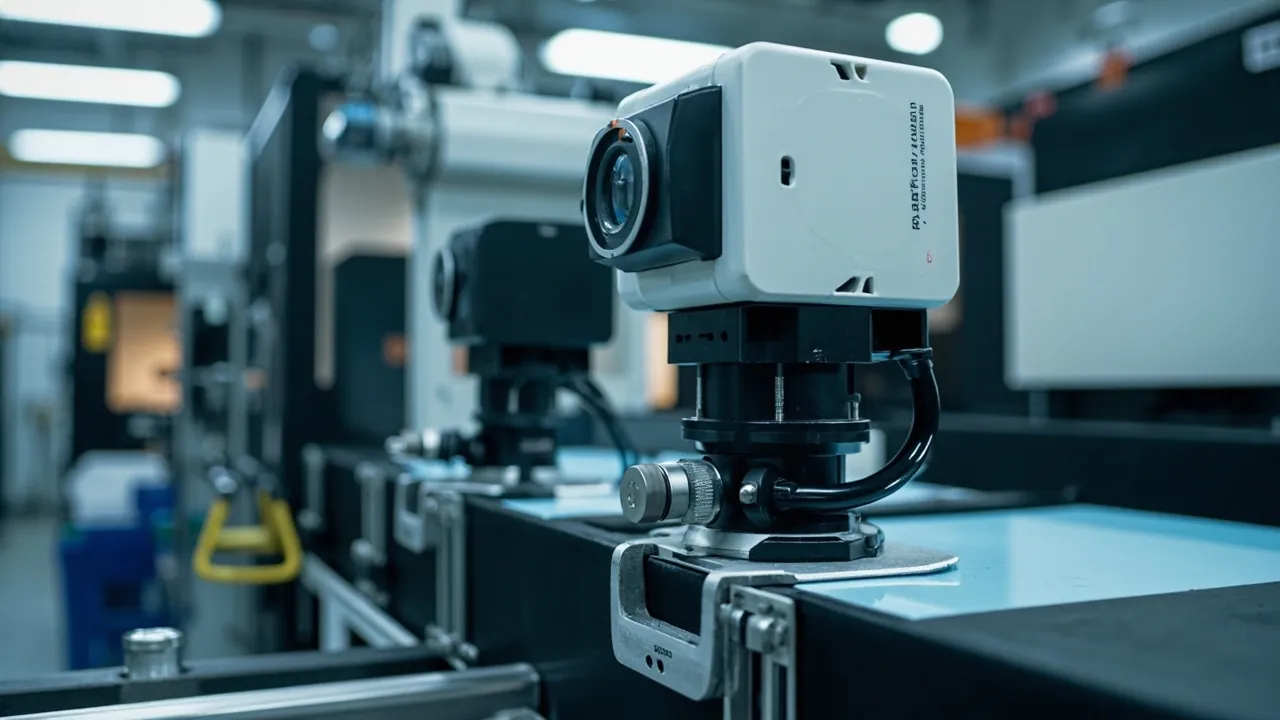
The key to shipping machine vision equipment is not impact resistance. It is keeping optical surfaces clean and transferring calibration state intact. The area in front of a CMOS sensor is a protective glass or IR-cut filter, and lens surfaces carry anti-reflective coatings. Once either picks up particles, outgassing deposits or fingerprints, the result is image dark spots, reduced contrast and edge shading. The more insidious loss is calibration failure: on a system that has already been calibrated, any small change in back focus, aperture ring, focus ring or camera-to-lens geometry invalidates the calibration parameters, and the customer must rebuild fixtures and recalibrate. The cost far exceeds the case itself. The correct approach is to pack camera and lens separately, relieve all optical faces throughout, use a clean closed-cell liner to limit micro-movement, and ship the calibration parameter files with the hardware so they remain traceable. This article is written for machine vision integrators, camera manufacturers and overseas channels, and provides structural parameters, protection classes and acceptance methods that can be applied directly.
Three disputes dominate machine vision deliveries. First, a fixed dark spot appears in the image and teardown finds outgassing residue on a rear lens element. Second, a telecentric or high-magnification lens cannot reach focus after installation, and the root cause is axial shock that shifted the lens group. Third, the camera produces images but accuracy is out of specification, because the angular relationship between lens and camera changed in transit and the calibration parameters the customer holds are no longer valid. What these three have in common is that the exterior shows no damage at all, yet the system cannot be used. The design logic for a machine vision case is therefore fundamentally different from an ordinary equipment case: its first objective is not drop resistance but optical cleanliness plus state preservation. This article splits a machine vision system into camera, lens, lighting, controller and cabling, and gives the packaging structure, cleanliness requirements, sealing class and test criteria for each. It also explains what JUNZHJIA can deliver in custom liners and OEM/ODM case development.
Table of Contents
- 1. Why the transport risk for machine vision equipment is often underestimated
- 2. Protection differences across cameras, lenses, lighting and controllers
- 3. Optical cleanliness control: particles, outgassing and electrostatic dust attraction
- 4. Why camera and lens must be packed separately
- 5. Force analysis for sensor cover glass, filters and lens mounts
- 6. Preserving calibration state and delivering parameter files traceably
- 7. Liner construction: relief, restraint and compliant support
- 8. Sealing class and condensation prevention: IEC 60529, GB/T 4208, IP65 and IP67
- 9. Vibration and shock control: from transport spectra to liner stiffness matching
- 10. Transport test references: ISTA, GB/T 4857, ASTM D4169 and MIL-STD-810H
- 11. Materials, flammability (UL94) and cleanliness requirements
- 12. Customization workflow, delivery documents and acceptance (AQL)
- 13. Frequently Asked Questions
- 14. Conclusion and Related Reading
1. Why the transport risk for machine vision equipment is often underestimated
Machine vision equipment is small, expensive and does not look delicate, so many projects ship it in an ordinary instrument case or a cardboard box. That judgment ignores three facts.
First, optical tolerances are extremely tight. The back focal distance of an industrial lens is measured in millimeters, and some high-magnification lenses have a depth of field of only a few tenths of a millimeter. The telecentricity of a telecentric lens is highly sensitive to the axial position of the lens group. A few tens of micrometers of axial displacement during transport is irrelevant on a mechanical part, but on an optical system it can make focus impossible or degrade measurement accuracy.
Second, calibration is an invisible asset. The value of a machine vision system lies not only in the hardware but in the calibration result: camera intrinsics such as focal length, principal point and distortion coefficients; extrinsics describing the spatial relationship between camera and robot or conveyor; and the pixel scale factor. These parameters are produced by the integrator before shipment and written into the program. If the relative position of lens and camera changes in transit, the whole parameter set must be redone. Recalibration requires a calibration target, fixtures and on-site downtime, and the cost is frequently dozens of times the price of the case.
Third, cleanliness loss is irreversible. Ordinary foam releases volatile organic compounds and plasticizers under vibration and thermal cycling. These form a hazy film on optical coatings that is difficult to remove without damage, since wiping can harm the coating. Dust particles can be blown off, but outgassing contamination often means the optical part is scrap.
Conclusion: the design priority order for a machine vision case should be optical cleanliness first, then state preservation, then impact resistance, then appearance. Many suppliers invert that order and produce a case that is thick and rigid yet contaminates or shifts the lens.
2. Protection differences across cameras, lenses, lighting and controllers
A machine vision system contains four component categories with clearly different protection needs.
| Component category | Typical weight | Sensitive factors | Protection priorities | Recommended sealing class |
|---|---|---|---|---|
| --- | --- | --- | --- | --- |
| Industrial camera, area or line scan | 0.1 to 3 kg | ESD, sensor surface cleanliness, connector pins | ESD control, sensor relief, interface protection | IP65 to IP67 |
| Lens, fixed focal, telecentric or microscope | 0.05 to 5 kg | Optical surface contamination, axial shift, mount damage | Optical face relief, axial restraint, mount protection | IP65 to IP67 |
| Lighting, ring, bar, backlight or coaxial | 0.1 to 3 kg | LED and light-guide structure, diffuser scratches | Diffuser relief, crush prevention | IP54 to IP65 |
| Vision controller, industrial PC, camera cables | 1 to 15 kg | ESD, moisture, pin deformation | ESD control, interface protection, cable bend radius | IP65 to IP67 |
Why they cannot be handled uniformly. A camera's core is the sensor and its circuit board, making it an ESD-sensitive item. A lens's core is the optical group, making it a cleanliness-sensitive item. The liner material requirements differ completely: a camera compartment needs ESD-safe material with surface resistance between 10^6 and 10^9 ohm, while a lens compartment needs clean closed-cell material with low outgassing and low particle shedding. Sharing one compartment liner forces a compromise that satisfies neither. Camera and lens should therefore be separated by a divider, and preferably shipped in different cases.
Lighting and controllers are comparatively tolerant, but three points still matter. Scratches on diffusers and light guides cannot be repaired. Lighting often ships with a driver and power supply that must be handled as electronics. And camera cables such as GigE, USB3, Camera Link and CoaXPress have fine connector pins that bend under compression from heavy objects, plus shielding that hates hard kinks, so keep the minimum bend radius at 8 to 10 times the outer diameter.
3. Optical cleanliness control: particles, outgassing and electrostatic dust attraction
Cleanliness is the primary metric for a machine vision case, and it has three control targets: particles, chemical outgassing and electrostatic attraction.
Particle control. Particles come from three sources: shedding from liner material, dust on case interior walls, and external particles introduced during packing. Controls include choosing closed-cell PE or EVA or IXPE materials with low shedding and avoiding open-cell sponge, friable foam and paper-based fillers; cleaning liners after machining by blowing or wiping and closing the case in a clean environment; fitting optical parts with clean PE bags, not ordinary PE bags, or protective caps over the optical face before packing; and ensuring interior walls have no burrs or machining chips.
Chemical outgassing control. This is the most commonly overlooked item. Ordinary EVA and PU sponge contain plasticizers, blowing agents and residual monomers that release volatile organic compounds as temperature rises, forming an irreversible haze on optical coatings. Controls include selecting low-VOC, low-outgassing formulations and requesting material data such as total volatile organic compound content and fogging test results; running ventilation aging on liners after machining, commonly 24 to 72 hours depending on material and process, so residual volatiles escape before the case is closed; keeping a clean barrier layer of clean PE bag or cleanroom cloth between optical part and liner so the optical face never touches foam; and adding thermal insulation or specifying a light-colored case where high temperatures are possible, for example inside containers or in open-air storage.
Electrostatic attraction control. Static attracts airborne particles onto optical faces and sensor windows. Controls include ESD-safe material in optical compartments with surface resistance between 10^6 and 10^9 ohm, which reduces charge generation while avoiding the rapid discharge that damages devices; mandatory ESD-safe liners and shielding bags in camera compartments containing circuit boards, as described in ESD shielding case options; grounded wrist straps and a grounded work surface for operators; and an ESD marking on the case, plus avoiding ordinary bubble wrap directly around a camera because it generates charge.
Cleanliness level reference. For high-end vision components such as high-magnification lenses or microscope objectives for semiconductor inspection, follow the ISO 14644 cleanroom classification approach and complete packing in an ISO Class 7 or better environment. General industrial vision components can be packed at a controlled clean workstation with positive pressure, cleanroom wipes and no paper waste.
4. Why camera and lens must be packed separately
This is the single most important design rule for a machine vision case. A camera with a lens attached forms a long cantilever in which the lens acts as a lever, and the mount plus body threads are the only load-bearing point. The combined assembly is also bulky with an offset center of gravity, so vibration and shock during transport produce an amplified bending moment at the mount.
Four reasons for separate packing:
Reason one: eliminating mount bending moment. Once separated, lens and camera each carry load through their own rigid surfaces, and the mount no longer takes bending. This matters most for long focal length or telecentric lenses, which can be 100 to 300 mm long.
Reason two: satisfying cleanliness requirements. The camera compartment can use ESD-safe material and the lens compartment can use clean, low-outgassing material, each at its optimum, with no compromise.
Reason three: simplifying spare-part management. Cameras and lenses have different failure rates and replacement cycles. Separate packing lets each ship and be repaired independently, avoiding unnecessary joint shipments.
Reason four: avoiding calibration contamination. If the customer had already calibrated the system, separation means recalibration. But that certain recalibration is better than uncertain drift after transport. The right answer is not to keep them attached in order to avoid recalibration, but to standardize the recalibration process and ship the calibration target and fixtures with the case.
What if the customer insists on shipping the assembly with the lens mounted? Then the case must include independent support for the front barrel of the lens, supporting the outer barrel rather than any glass element, with the support point below or on both sides of the lens center of gravity. The mount must not be the only load path. The case length grows substantially, so use a lengthened case with multiple support points along the long axis.
5. Force analysis for sensor cover glass, filters and lens mounts
Sensor cover glass. The area in front of a CMOS or CCD sensor normally has a cover glass or IR-cut filter, with a gap of tens to hundreds of micrometers to the sensor. High-frequency vibration and shock can crack the filter, debond the adhesive, or let dust into the gap where it settles on the sensor. Sensor contamination is practically impossible to clean in the field and requires a factory return.
Protection points: keep the original dust cap in place, usually a threaded plastic cap, and confirm it is tight before packing. If already opened, fit a new dust cap or clean protective cap and never leave the camera exposed. Do not leave a camera without either a lens or a dust cap for longer than necessary. Do not let the liner press on the center of the dust cap; direct pressure to the camera housing instead. For cameras with C-mount, CS-mount or M42 and M58 threads, prevent movement in the case from denting or deforming the threaded interface.
Lens mount. The bayonet is the flange-distance datum, and its flatness and concentricity directly determine image quality. Impact can deform the flange face, wear the bayonet lugs, or change the angular relationship between lens and camera. Protection points: fit protective caps to both sides, meaning a rear lens cap and a body cap, with no hard particles trapped between cap and mount. Support the lens at two points using the front outer barrel and the rear mount seat, never a single middle point that creates a cantilever. Orient long lenses along the long case axis and add a third support at the center of gravity.
Focus and aperture rings. For manual lenses, particularly telecentric and microscope lenses, check before shipment that the focus ring, aperture ring and any locking screws are secured. If the customer requires factory settings to be preserved, use locking screws or apply tamper-evident tape across the ring as an anti-rotation mark, then verify the mark position on arrival. This is a low-cost but effective state-preservation measure.
Lens threads and filters. Front-mounted filters such as polarizers or bandpass filters should be removed and packed separately for two reasons: large-diameter filters crack under impact, and the polarization angle setting is easily lost. Use a dedicated filter case or an independent liner compartment.
6. Preserving calibration state and delivering parameter files traceably
Calibration is not merely a software matter. It is an asset made of hardware state, parameter files and fixtures together. What a packaging plan can do is keep that asset reproducible through transport.
Four state-preservation measures:
- Anti-rotation marks. Apply marks, using marker paint or tamper-evident tape, at the lens-to-camera mount interface, on the focus and aperture rings, and at the lens-to-bracket interface. Verify alignment on arrival.
- Parameter files travel with the goods. Deliver calibration files, covering intrinsics, extrinsics, distortion coefficients, pixel scale factor, calibration date and version, on a USB drive or as a QR code with the case, annotated with the corresponding equipment serial number. If the customer uses GenICam or a vendor calibration tool, include the configuration export as well.
- Calibration target protection. A calibration target on a glass or ceramic substrate is a high-precision, fragile item. Give it a dedicated case or an independent liner compartment with optical face relief and four-corner support. Once a target is scratched or deformed, the entire calibration loses its reference.
- Assembly and reset instructions. Provide the assembly sequence, torque requirements, commonly 0.6 to 1.2 N-m for mount screws subject to manufacturer specification, and the post-reset verification items.
Engineering judgment on whether recalibration is needed: strictly speaking, any vision system that has traveled should be re-verified for high-accuracy applications. Start with a quick verification: capture an image of the calibration target and check whether reprojection error and pixel scale factor fall within tolerance. If they do, the system can be used; if not, recalibrate. The goal of the packaging plan is to make quick verification pass routinely, not to guarantee that recalibration is never needed. Any claim that no verification is required after transport is unsound.
Rule of thumb: separate packing plus anti-rotation marks plus clean protective caps substantially raises the first-pass rate of post-arrival quick verification. Shipping the assembly mounted with no anti-rotation measures carries a clearly higher risk of calibration drift.
7. Liner construction: relief, restraint and compliant support
Machine vision components are light but vary widely in stiffness. The key to liner design is light contact, multi-point support and full relief of optical faces.
Relief design. Cut a relief cavity opposite every optical face: front and rear lens elements, the camera sensor window or dust cap, lighting diffusers, and calibration target surfaces. No liner material or adhesive may enter the cavity. Recommended cavity depth is at least 10 mm, with a diameter 10 to 20 mm larger than the optical face.
Restraint design. Use contour fitting plus local restraint blocks: mold the liner to the part contour for surface contact, then add blocks in the critical directions, axial and radial, to limit movement to about 0.5 to 1 mm. Avoid a fully wrapping, hard-compressed design, because interference fits apply unnecessary force to optical faces during assembly.
Compliant support. For long lenses and long bar lights, use multi-point compliant support rather than a single rigid support. Add a 2 to 5 mm soft pad of closed-cell PE sheet or clean flocked fabric between part and liner, which raises friction while damping micro-vibration.
Compartments and independent cavities. Camera, lens, lighting, controller, cabling and calibration target should each have their own compartment, separated by EVA dividers. For multiple small lenses, a honeycomb compartment liner with independent relief per cell works well. Where models change frequently, use a removable divider system so cavity dimensions can be adjusted without changing the case, as described in case removable divider systems.
Liner molding route. For single units or small batches, CNC carving gives plus or minus 0.5 mm accuracy with no tooling and fast delivery. Above roughly 500 units per year, compression molding gives better consistency and lower unit cost. Given the multi-model, low-volume pattern typical of machine vision projects, a common case with model-specific liners is recommended, with a CNC first article validated before tooling. The underlying cost logic is explained in custom protective case mold cost analysis and the custom EVA foam insert process.
On cushioning layer thickness. Vision components are light, so the main drop risk is not overload but rebound and secondary impact. A total liner thickness of 30 to 60 mm is recommended, with 20 to 40 mm of outer EPE for energy absorption and EVA in the middle for molding and restraint. Excessively thick soft cushioning actually lets a light part bounce inside the case. Material comparisons are covered in case foam material comparison.
8. Sealing class and condensation prevention: IEC 60529, GB/T 4208, IP65 and IP67
Sealing class selection depends on the logistics route and the sensitivity of the optical components. Classes are defined by IEC 60529 and GB/T 4208.
| Class | Dust | Water | Applicable scenario for machine vision components |
|---|---|---|---|
| --- | --- | --- | --- |
| IP54 | Dust protected, limited ingress | Splash resistant | Domestic road transport, short transfers, movement inside a cleanroom |
| IP65 | Dust tight | Water jet resistant | Ocean freight plus inland delivery, open-air handling, typical industrial sites |
| IP67 | Dust tight | Temporary immersion, 1 m for 30 min | Multimodal transport, rainy season, quay storage, high-humidity regions |
Why IP65 is the sensible minimum for vision components. Optical faces and sensor windows are most vulnerable to dust and condensation. The interior of an ocean container stays at 70 to 90 percent relative humidity for extended periods, and day-night temperature cycling causes condensation. A water film on an optical surface can leave stain marks and even promote mold growth on coatings. Sealing at IP65 or better combined with desiccant keeps internal humidity at a low, stable level.
Three condensation prevention measures:
- Desiccant plus humidity indicator card. Place desiccant according to case volume, generally 30 to 100 g per case depending on volume and shipment duration, and include a humidity indicator card so the condition can be judged at a glance on arrival.
- Pressure-equalization valve. An IP67 sealed case must include a breathable but water-tight structure, typically a PTFE membrane, to equalize differential pressure from day-night temperature swings and from air or high-altitude transport, preventing a seized lid or an instantaneous seal rebound that draws in moisture. Selection guidance is in case pressure equalization valve.
- Temperature soak. State in the work instruction that the case should stand for 4 to 12 hours after arrival until its internal temperature approaches ambient before opening. This markedly reduces condensation and matters especially for optical components, because condensation at the moment of opening lands directly on the glass.
Gasket maintenance. EPDM or silicone gaskets should be compressed 30 to 40 percent. Wipe the seal channel before closing the case, because sand and debris create leak paths. Cleaning methods are covered in how to clean a protective case.
An often overlooked alternative. For purely in-plant transfer inside a cleanroom, high-grade sealing may not be necessary. A clean case plus a single-use clean bag gives a two-layer approach that is inexpensive and very clean, with the outer case providing mechanical protection. Total cost can be lower than a high-sealing case. Choose between the two based on whether the logistics route carries dust and humidity risk.
9. Vibration and shock control: from transport spectra to liner stiffness matching
Packaging design is essentially about moving the natural frequency of the packaging system away from the excitation bands of the transport environment, and about reducing peak acceleration to a level the equipment can survive.
Typical transport excitation:
| Transport mode | Dominant frequency band | Typical peak acceleration, engineering value |
|---|---|---|
| --- | --- | --- |
| Road truck, paved surface | Mainly 2 to 15 Hz plus 20 to 100 Hz | 0.3 to 1.5 g |
| Road, unpaved or rough | 5 to 50 Hz | 1 to 3 g |
| Rail | 1 to 10 Hz | 0.5 to 2 g |
| Ocean freight inside container | 1 to 20 Hz including low-frequency sway | 0.2 to 1 g |
| Handling drop by forklift or hand | Impulse lasting a few milliseconds | 20 to 100 g |
Stiffness matching principle. Liner stiffness should match the mass of the packed item. Too soft and the item swings widely and strikes the case wall; too hard and cushioning is lost. For light vision components under 2 kg, use medium-hardness EVA at 60 to 90 kg/m3 with a thin compliant pad rather than very soft sponge. A practical criterion: after packing, pushing the item by hand should produce less than 1 mm of movement, and extraction force should be between 10 and 40 N, lower than for robot components because vision parts are lighter.
Resonance avoidance. The natural frequency of the packaging system can be shifted by adjusting liner thickness and support area. The general goal is to place system natural frequency below 5 Hz or above 50 Hz, avoiding the most common transport excitation bands. This is normally confirmed by test, meaning swept-sine testing on a vibration table, rather than by calculation alone.
Shock indicator labels. Apply a shock indicator label to the outside of the case with a selectable threshold of 25 g, 50 g or 100 g, and place a temperature and humidity logger inside. Reading the data on arrival shows whether transport exceeded limits. For high-value vision components this evidence chain costs very little and is worth a great deal in liability assignment.
On camera connectors. GigE, USB3, Camera Link and CoaXPress interfaces have fine pins. Disconnect all of them for transport and fit dust caps. Coil cables to a diameter of at least 150 mm, or 8 to 10 times the outer diameter, and do not bend within 50 mm of either connector.
10. Transport test references: ISTA, GB/T 4857, ASTM D4169 and MIL-STD-810H
The ISTA series. ISTA 2A covers simulated performance testing of individual packages up to 68 kg, including conditioning, drop, vibration and compression. ISTA 3A covers parcel delivery. ISTA 3E covers unitized loads on pallets. Machine vision components are mostly small and high-value, so they are commonly organized against ISTA 2A or 3A. The workflow is detailed in ISTA transport testing procedure.
The GB/T 4857 series. The Chinese basic test standard for transport packages, aligned with the ISO 4180 framework and covering drop, stacking, vibration and impact. Domestic customers usually require a report to this standard. See GB/T 4857 transport packaging testing.
ASTM D4169. A performance test standard for distribution cycles that combines test sequences by defining a distribution cycle and an assurance level, suited to multimodal evaluation. See ASTM D4169 distribution cycle testing.
MIL-STD-810H. Frequently cited for its method-level environmental testing, including Method 501 high temperature, 502 low temperature, 507 humidity, 514 vibration and 516 shock. It must be stated clearly that citing MIL-STD-810H means only that the environmental test methodology is referenced. It does not mean the product holds any military certification, and it does not mean the product is a military product. Its methodology applies equally well to civilian industrial equipment packaging, particularly in how vibration and thermal cycling sequences are organized. Related guidance is in MIL-STD-810H case compliance.
Recommended test criteria for machine vision components, as engineering values to be confirmed against the actual logistics route:
| Test item | Suggested parameters | Pass criteria |
|---|---|---|
| --- | --- | --- |
| Temperature and humidity conditioning | Minus 20 to plus 60 degrees Celsius at 85 percent RH, cycling | No condensation stains, no coating haze, no mold |
| Drop | One corner, three edges, six faces; 600 to 900 mm common for small items | No optical damage, no mount deformation, function intact |
| Random vibration | 5 to 200 Hz, PSD per ISTA 2A, 30 to 60 minutes per axis | No displacement, no loose mount, no dark spots in image |
| Compression | Actual layers times a safety factor of 1.5 to 2.0 | No permanent case deformation, no compression of optical parts |
| Cleanliness verification | Visual plus bright-field and dark-field inspection after opening | No visible particles or haze on optical faces |
Functional criteria should be written explicitly. Unlike mechanical parts, a vision component is only acceptable if imaging criteria are met. For example, capture an image of a standard target and check for no anomalous bright spots under dark field, no dark spots under bright field, and no abnormal shading at the edge of field. Confirming only that there is no visible external damage is not sufficient evidence that transport was acceptable.
11. Materials, flammability (UL94) and cleanliness requirements
Case material comparison for machine vision applications:
| Material | Cleanliness | Impact resistance | Flammability | Application |
|---|---|---|---|---|
| --- | --- | --- | --- | --- |
| Copolymer PP | Medium | Good | UL94 HB, modifiable to V-0 | Outer case, cost-effective option |
| ABS | Medium | Good | UL94 HB to V-0 | Outer case with high appearance requirements |
| PC | Medium | Excellent | UL94 V-0, V-2 in thin walls | High strength or windowed needs |
| Aluminum case with clean coating | High | Good | Depends on coating | High cleanliness, semiconductor applications |
| Closed-cell PE or EVA liner | High | Moderate | UL94 V-0 in flame-retardant grades | Optical compartments, recommended |
| ESD-safe PE or EVA liner | Medium to high | Moderate | UL94 V-0 in flame-retardant grades | Camera and controller compartments |
UL94 rating explanation. HB is the lowest horizontal-burning rating. V-2, V-1 and V-0 are vertical-burning ratings of increasing severity, and 5VB and 5VA are stricter. For machine vision cases, the recommendation is case material at UL94 HB or better and liner material in optical and electronics compartments at UL94 V-0. If the case enters a semiconductor or specific production facility, the whole case may be required at V-0 with third-party reports.
The conflict between cleanliness and flame retardancy. Some flame-retardant modified foams achieve their rating with inorganic fillers, and those fillers can increase particle shedding and outgassing. When selecting material, request particle shedding data, VOC or fogging test results and UL94 reports together, not the flame rating alone. JUNZHJIA can match liner materials to a customer's cleanliness level using the ISO 14644 classification approach, and can supply material property tables, RoHS and REACH declarations and UL94 reports subject to material batch availability.
Hinges, latches and gaskets are the life-limiting parts. Evaluate hinges and latches by open-close cycles, commonly 5000 to 20000, and replace gaskets on a 2 to 4 year cycle. Related construction guidance is in toolbox hinge, latch and seal construction and protective case service life.
12. Customization workflow, delivery documents and acceptance (AQL)
Standard JUNZHJIA customization workflow, with milestones adjusted per project:
- Requirements gathering, 1 to 3 working days: equipment list and models, dimensions and weights, optical face identification for relief, cleanliness level, calibration state, logistics route, target IP class, annual volume.
- Concept and structural design, 3 to 7 working days: case dimensions, material, zoning plan, liner relief and restraint geometry, with 2D and 3D deliverables for confirmation.
- First article, 7 to 15 working days: CNC liner plus first-article case shell, with physical packing validation confirming relief positions, extraction force and that no optical face is touched.
- Clean processing and aging, 2 to 5 working days: ventilation aging and cleaning of the liner to reduce VOC and particle shedding.
- Test validation, 5 to 10 working days: drop, vibration and compression testing to the customer-specified standard, plus imaging criteria verification under dark and bright field.
- Production and delivery: compression-molded liner or molded case shell, full first-article inspection, AQL sampling in production, and delivery documents with the goods.
Four documents recommended to ship with the case:
- Packing and unpacking SOP: optical face protection steps, how to align with relief cavities, connector disconnection and protection requirements, and temperature soak duration.
- Clean packing work instruction: operating environment, glove and cleanroom wipe requirements, ESD wrist strap requirements.
- Calibration state note: anti-rotation mark locations, list and version of parameter files, and the recommended quick verification method.
- Material and compliance declarations: property tables, VOC or particle shedding data where available, UL94 reports, RoHS and REACH declarations.
Acceptance recommendations, with AQL per GB/T 2828.1 and ISO 2859-1:
| Inspection item | Defect class | Recommended AQL | Method |
|---|---|---|---|
| --- | --- | --- | --- |
| Appearance, color, scratches, burrs | Minor | 2.5 | Visual, color card |
| Relief cavity position and depth | Major | 0.65 | Fixtures, CMM or vision measurement |
| Dimensions and fit | Major | 1.0 | Gauges and fixtures |
| Liner particle shedding and cleanliness | Major | 1.0 | Visual plus bright light, wipe test with cleanroom cloth |
| Seal performance | Major to critical | 0.65, or 100 percent | Pressure decay or IEC 60529 IPX5 and IPX7 |
| Liner fit and extraction force | Major | 1.0 | Physical assembly, force gauge |
| Marking and documents | Minor | 4.0 | Visual and document verification |
Relief cavity inspection is the critical item unique to machine vision cases. Confirm the relative position of each relief cavity and its optical face using a fixture or vision measurement, with a tolerance of about plus or minus 0.5 mm. Insufficient relief means the liner presses on the optical face or filter in transit, while excessive relief means restraint is lost. Related acceptance methods are described in custom case acceptance and AQL sampling.
13. Frequently Asked Questions
Q: Can a machine vision camera and lens ship in the same case, or must they be separated? A: Separation by compartment is recommended, and separate cases are better still. The core value of separation is eliminating mount bending moment. A camera with a lens attached forms a long cantilever in which the lens acts as a lever and the mount plus body threads are the only load-bearing point, so transport vibration produces amplified bending at the mount, which is especially damaging for long focal length and telecentric lenses. Once separated, lens and camera each carry load through their own rigid surfaces and the mount is unloaded. There is also a material conflict: a camera contains circuit boards and needs ESD-safe material with surface resistance between 10^6 and 10^9 ohm, while a lens is an optical item needing clean, low-outgassing material, so a shared liner forces a compromise that satisfies neither. If the customer insists on shipping the assembly mounted, provide independent support for the front outer barrel of the lens with support points below or on both sides of the lens center of gravity, never letting the mount be the only load path, and lengthen the case accordingly.
Q: A lens cannot reach focus after transport. What packaging problem usually causes that? A: The most common cause is axial shock that shifted the lens group. Back focal distance is measured in millimeters, a high-magnification lens may have a depth of field of only a few tenths of a millimeter, and the telecentricity of a telecentric lens is extremely sensitive to the axial position of the group. A few tens of micrometers of axial movement that would be irrelevant on a mechanical part can make focus impossible on an optical system. Three improvement paths exist. Separate the camera and lens to eliminate mount bending. Add axial restraint blocks to the liner and limit axial movement to about 1 mm. Support the lens at the front outer barrel and the rear mount seat as two points, orient long lenses along the long case axis, and add a third support at the center of gravity so the lens is not cantilevered. It is also worth checking whether the focus ring and locking screws were secured before shipment and whether anti-rotation marks have shifted. If the lens group has genuinely shifted, factory realignment is usually required and it cannot be corrected in the field.
Q: A hazy film appears on a lens or sensor surface. Is transport responsible? A: It is very likely outgassing from the liner material. Ordinary EVA and PU sponge contain plasticizers, blowing agents and residual monomers that release volatile organic compounds as temperature rises, forming a hazy film on optical coatings. This is the hardest class of contamination to deal with, because wiping can damage the coating and the damage is often irreversible, whereas dust particles can simply be blown off. There are four controls. Select closed-cell materials with low VOC and low outgassing and request total VOC and fogging test data. Run ventilation aging on liners after machining, commonly 24 to 72 hours, so residual volatiles escape before the case is closed. Keep a clean PE bag or cleanroom cloth barrier between optical parts and the liner so no optical face touches foam directly. Where high temperatures are possible, add thermal insulation or specify a light-colored case. Note that paper-based fillers and open-cell sponge are also high-risk materials.
Q: What sealing class does a machine vision case need? Is IP67 necessary? A: IP65 is the sensible minimum, and whether to go to IP67 depends on the logistics route. Optical faces and sensor windows are most vulnerable to dust and condensation, and ocean container interiors stay at 70 to 90 percent relative humidity for extended periods, with day-night temperature cycling producing condensation that can leave stains or even promote mold on coatings. Any route involving ocean freight, multimodal transport, open-air handling or quay storage justifies IP65 as a floor, and IP67 is worth considering where there is rainy-season handling, quay storage or high-humidity transshipment. Note that IP67 must include a pressure-equalization valve, otherwise day-night temperature differences and air or high-altitude transport will seize the lid or cause a seal rebound that draws in moisture. If the whole route is in-plant or short domestic delivery in a cleanroom environment, a clean case plus a single-use clean bag can substitute for high-grade sealing at potentially lower total cost. Details of IP65 versus IP67 are covered in the IP67 protective case article.
Q: What transport tests does machine vision equipment need? Is visual inspection enough? A: Visual inspection alone is not enough. A vision component is only acceptable when imaging criteria are met, because sensor contamination, coating haze and lens group displacement are completely invisible externally. A recommended test set is temperature and humidity conditioning from minus 20 to plus 60 degrees Celsius at 85 percent RH, drop and random vibration per ISTA 2A or GB/T 4857, compression at the actual stacking layers, and optionally an ASTM D4169 distribution cycle. For criteria, add imaging verification beyond appearance and function: capture an image of a standard target and check for no anomalous bright spots under dark field, no dark spots under bright field, and no abnormal edge-of-field shading, then confirm reprojection error or pixel scale factor is within tolerance. If the customer or end user cites MIL-STD-810H, state that only the test methods are referenced, such as Methods 501, 502, 507, 514 and 516, and that this is not a military certification. The workflow is described in the ISTA transport testing procedure article.
Q: How deep should liner relief cavities be, and how are they inspected? A: Cavity depth and diameter depend on the specific optical face dimensions. A general engineering guide is that no liner material or adhesive may enter the cavity, depth should be at least 10 mm, and diameter should be 10 to 20 mm larger than the optical face. Objects that require relief include front and rear lens elements, the camera sensor window or dust cap, lighting diffusers and calibration target surfaces. For inspection, confirm the relative position of cavity and optical face with a fixture or vision measurement at a tolerance of about plus or minus 0.5 mm, and run a physical packing validation confirming that no optical face has any contact point when packed. Insufficient relief means the liner presses on the optical face or filter during transport, while excessive relief loses restraint, and neither is acceptable. The JUNZHJIA approach is to produce a CNC first article and validate it by physical assembly before committing to tooling, which substantially reduces the risk of mispositioned relief.
Q: Does calibration need to be redone after transport, and can packaging guarantee that it will not be? A: The rigorous answer is that packaging raises the probability of passing quick verification but cannot guarantee that verification is unnecessary. Calibration is an asset made of hardware state, parameter files and fixtures, not just software. Four things can be done on the packaging side. Apply anti-rotation marks at the lens-to-camera mount interface and on the focus and aperture rings, then verify on arrival. Deliver calibration files covering intrinsics, extrinsics, distortion coefficients, pixel scale factor, date and version with the goods and annotated with the serial number. Give the calibration target a dedicated compartment with optical face relief and four-corner support. Provide the assembly sequence, torque requirements, commonly 0.6 to 1.2 N-m for mount screws subject to manufacturer specification, and the post-reset verification items. In engineering practice, start with a quick verification on arrival using a calibration target image to check reprojection error and pixel scale factor against tolerance, then either use the system or recalibrate. Any claim that no verification is required after transport is unsound.
Q: How should high-cleanliness vision components such as semiconductor inspection lenses be packed? A: Organize it around cleanroom principles. For material selection, use closed-cell PE or EVA or an aluminum case with a clean coating, avoiding open-cell sponge and paper-based fillers, and request particle shedding and VOC data rather than looking only at UL94 flame rating, because some flame-retardant fillers carry higher shedding and outgassing risk. For environment, high-end vision components can be packed in an ISO Class 7 or better environment following the ISO 14644 classification approach, while general industrial vision components can be packed at a controlled clean workstation with positive pressure, cleanroom wipes and no paper waste. For process, operators should wear ESD wrist straps and cleanroom gloves, liners should be ventilation aged and cleaned after machining, and optical parts should be fitted with clean PE bags or protective caps. For verification, perform visual plus bright-field and dark-field inspection after opening. JUNZHJIA can match liner materials to a customer's cleanliness level and provide the corresponding material declarations and test coordination.
Q: How does machine vision case acceptance differ from ordinary equipment case acceptance? A: The biggest difference is that relief cavity inspection becomes a critical item. An ordinary equipment case mainly checks dimensional fit, sealing and structural strength. A vision case must additionally confirm the relative position of each relief cavity and its optical face, ideally using a fixture or vision measurement with a tolerance of about plus or minus 0.5 mm. The second difference is added particle shedding and cleanliness inspection, which can include visual inspection under bright light and a wipe test with cleanroom cloth to check for transferable particles. The third difference is added imaging criteria verification using a standard target to check dark-field bright anomalies, bright-field dark spots and edge-of-field shading. The remaining items match conventional practice: appearance, dimensions, seal performance by pressure decay or IEC 60529 IPX5 and IPX7, hinge and latch function, liner fit and extraction force, and marking and documents. AQL can follow GB/T 2828.1 and ISO 2859-1, with seal performance inspected 100 percent. General methods are described in the custom case acceptance and AQL sampling article.
14. Conclusion and Related Reading
The value of a machine vision camera and lens case lies in turning invisible losses into a manageable process: relief cavities keep optical faces untouched, clean low-outgassing materials keep coatings uncontaminated, anti-rotation marks and parameter files keep calibration state traceable, and sealing plus desiccant keep condensation and stains away. If any one of those four is missing, a camera or lens that looks perfect externally can still be unusable at the customer site, and the cost of repair or recalibration far exceeds the case.
For procurement and engineering teams, a practical four-step plan is: first, identify every optical face and calibration datum on the equipment and define relief positions for each; second, set the sealing class from the logistics route and decide on desiccant and a pressure-equalization valve; third, design the compartmented liner and validate a CNC first article by physical assembly to confirm relief and restraint; and fourth, include parameter files, anti-rotation mark records and quick verification methods in the delivery documents. JUNZHJIA, operated by Kexin New Materials (Guangdong) Co., Ltd., supports machine vision camera makers, lens makers, integrators and overseas channels with custom clean liners, OEM/ODM case structure development, model-specific gaskets and pressure-equalization valves, plus material property tables, VOC and particle shedding data, UL94 reports, RoHS and REACH declarations and test coordination, covering everything from single-piece first articles to volume delivery.
Related Reading