

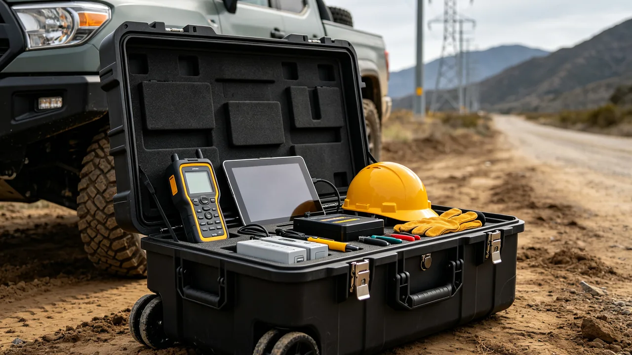
Protecting excavator buckets and hydraulic cylinders in transit means solving two requirements that pull in opposite directions. On one side sit cast-and-welded structures weighing several tonnes, which demand rigid restraint and generous contact area. On the other side sit hydraulic surfaces measured in micrometres, which demand compressible cushioning and absolute freedom from side load. Three conclusions summarise the engineering answer: bucket assemblies must be graded by bucket type and mass rather than by outline dimensions; each tooth and adapter needs its own dedicated pocket instead of being strung together; and hydraulic cylinders must never carry lateral load at any point in the logistics chain, with every port double-plugged and system cleanliness managed to an ISO 4406 target. Buckets are normally shipped detached from the carrier machine, which means drops, rollovers and fork-tine strikes all happen in the container yard or at the port, precisely where direct supervision is thinnest.
When earthmoving machines are exported, the bucket, cylinders, pins and slew bearing usually travel as separate packages and are reassembled on site. That split shipment is the highest-risk segment of the whole journey. A chipped bucket edge becomes a stress concentration point once the machine starts digging, while a scratched piston rod coating turns into a cutting edge against the rod seal and guarantees weeping within a few hundred operating hours. The sections below work through the failure chain item by item, covering restraint methods, load verification, liner selection, sealing grades, test references and outbound inspection criteria, so that machine builders, parts traders and export agents can use them directly for case selection and acceptance.
Table of Contents
- The Core Conflicts an Excavator Parts Case Must Resolve
- Bucket Mass Grading and Lifting Constraints
- Protecting Tooth Adapters, Teeth and Side Cutters
- Cylinder Barrel and Piston Rod Surface Protection
- Hydraulic Cleanliness and Port Plugging
- Rust Prevention for Pins, Bushings and Tension Springs
- Load Layout for Slew Bearings and Travel Gearboxes
- Case Frame and Load Class Verification
- Choosing Liner Materials for Heavy Loads
- Sealing, Breather Valves and Salt Fog Exposure
- Transport and Environmental Test References
- Outbound Inspection and Sampling Judgement
- Frequently Asked Questions
- Conclusion and Related Reading
The Core Conflicts an Excavator Parts Case Must Resolve
The first conflict is rigidity against compliance. A bucket is a rigid body and needs constraint that says "do not move", which is delivered by hard limiters and large contact patches. A piston rod is a precision body and needs constraint that says "do not press hard", which is delivered by compressible elastomer layers. If one liner language is applied to both bodies inside a single case, one of them will be sacrificed, and it is almost always the piston rod, because it is visually far less conspicuous than a bucket.
The second conflict is mass against handleability. A 1.2 m3 class backhoe bucket in cast-welded construction commonly weighs between 600 and 900 kg before teeth are fitted. Designing a single case large enough to swallow the bucket drives case tare weight and lifting requirements upward, raises freight cost, and may exceed whatever handling equipment the site actually has. A more practical architecture separates the problem: the bucket travels in an open cradle or a fumigation-free timber crate with a custom liner, while cylinders, pins and valve blocks travel in dedicated protective cases, with both tied together by a numbered packing unit list.
The third conflict is time. Excavator parts leave the warehouse against service work orders, so the window between disassembly, packing and dispatch is short. Any solution requiring on-site fabrication of liners is therefore unreliable. The liner has to be moulded to drawing at order stage so that it can be loaded the moment it arrives. This is the core value of a custom insert over pour-in-place foam, and the dimensional logic behind pocket depth and draft can be reviewed in custom foam insert pocket design.
A blunt field test for whether an excavator parts case is acceptable: load it, tilt it 30 degrees and hold for ten minutes, then return it upright. When the lid opens, no individual item should show a visible displacement mark.
Bucket Mass Grading and Lifting Constraints
Bucketing risk in transit scales roughly with mass, but the real dividing line is centre of gravity location rather than tonnage. A standard digging bucket carries its centre of gravity close to the curved bottom shell, low and stable. Rock buckets, trenching buckets and tilting buckets often have centres well away from the geometric middle, which makes them prone to rolling during lifting. Grading should therefore start with bucket type and treat tonnage as the second dimension.
Grading decides three things: liner compression, number of restraint points and whether a steel skeleton is required. As a working rule, restraint points should be placed symmetrically about the centre of gravity and number no fewer than four. Liner compression should be taken between 8 and 15 percent, using the lower end for heavy buckets to suppress rebound and the upper end for lighter buckets to keep loading and unloading manageable.
| Bucket type | Typical capacity | Empty mass (kg) | Centre of gravity | Recommended packing unit |
|---|---|---|---|---|
| --- | --- | --- | --- | --- |
| Standard digging bucket | 0.8 - 1.2 m3 | 550 - 900 | Low, near bottom shell | Fumigation-free crate, full-face base support |
| Rock bucket | 1.0 - 1.6 m3 | 850 - 1400 | Forward biased toward adapters | Steel skeleton case, four hard limiters, tooth guards |
| Trenching bucket | 0.3 - 0.6 m3 | 400 - 700 | Elongated along length | Long cradle with mid-span auxiliary supports |
| Tilting bucket with cylinder | 0.6 - 1.0 m3 | 700 - 1100 | Moves with cylinder position | Cradle plus isolated cylinder cavity |
| Skeleton or screening bucket | 0.8 - 1.5 m3 | 900 - 1500 | High open top, snag prone | Steel skeleton case with top hold-down beam |
Tilting buckets and quick couplers deserve a separate warning. Both carry hydraulic ports, and both must be plugged and capped before loading. Residual oil otherwise forms a film inside the case that contaminates the liner, and in a humid sea freight atmosphere it binds dust into an abrasive paste.
Lifting must match case design. If only a forklift is available at the destination, the case base needs at least 100 mm of fork entry height with load-bearing plates positioned exactly where the tines will sit, so that tines cannot punch through the bottom liner. When slings are used, lifting points must be clearly marked and no sling may be attached anywhere other than at the reinforcing ribs.
Protecting Tooth Adapters, Teeth and Side Cutters
Bucket teeth are the highest-turnover wear part on an excavator and, precisely because of that, they receive the least care in transit: strung on a wire and dropped in a corner, or loaded loose beside the bucket. The consequence is not simply blunted tips. The more serious damage happens at the adapter interface and the pin bore, where burrs raised by impact prevent the tooth from bedding down. A tooth that cannot seat tightly will chatter under load, and that chatter converts into fretting wear and eventually cracking at the adapter root.
The correct approach is dedicated pockets: one pocket per adapter position, one tooth per pocket, tips oriented consistently and touching nothing. Pocket floors need 5 to 8 mm of cushioning, tooth bodies should be flanked by liner material, and the tip zone should be left clear. Where teeth ship already fitted to the bucket, each tooth needs its own cap protector in polyurethane at Shore A60 to A75. Harder material abrades the tip; softer material provides no real cushioning.
Side cutters, corner teeth and bottom wear strips are castings with thin edges and poor impact tolerance. They should be laid flat in a single layer and never stacked. Where multiple layers are unavoidable, a rigid divider as wide as the case must carry the load between layers so that weight passes into the case wall rather than through the castings below.
Pins, tooth pins and retaining clips are the other major loose-item source. They are numerous, small and irregular, so mixed loading means they collide with each other and also migrate beneath the bucket to create point contacts. The right answer is a compartmented tray: one compartment per size, sloped floors for easy retrieval, and a size label on the tray lid.

The restraint logic for earthmoving castings overlaps heavily with mining equipment accessories, and the treatment of casting edges and pin bores in construction and mining machinery parts packing follows the same failure reasoning.
Cylinder Barrel and Piston Rod Surface Protection
Hydraulic cylinders generate the largest single claim value in excavator parts logistics. The reason is simple. Piston rod coatings, usually hard chrome or ceramic, are only tens of micrometres thick. Hardness is high but toughness is low, so any metal-to-metal contact produces scoring or spalling. The raised lip left at the edge of a score becomes a sharp edge that travels with the rod and cuts the seal lip open, after which continuous weeping is inevitable.
Protection works at three levels. The first is mechanical isolation: the full exposed rod length is sleeved in a soft cover, sized slightly larger than rod diameter, in expanded polyethylene or nitrile rubber, secured at both ends with ties that are snug rather than deforming. The second is axial restraint: the cylinder must sit horizontal or near-horizontal, supported at both ends by saddles with curved faces matching barrel outside diameter, with a contact angle of at least 120 degrees so that load is spread rather than concentrated on a line. The third is port plugging: every port receives a threaded plug plus a blind flange, with sealant tape applied sparingly at the thread, and return and pilot ports confirmed one by one rather than assumed.
Cleanliness inside the barrel matters just as much. Barrels are normally flushed and preserved before dispatch, but a barrel that travels with an open port will draw humid, salt-laden air inside, producing pitting on the honed bore. Once pitting falls inside the stroke envelope, the cylinder develops internal leakage, showing up as weak movement and elevated oil temperature. Plugging must therefore follow flushing immediately, with no open station in between.
Where the cylinder ships attached to a linkage assembly, the transport condition should keep the rod fully retracted so that the barrel carries the protection duty. If geometry prevents retraction, the exposed rod length must be sleeved in full and given an auxiliary support saddle. It must never be left cantilevered.
A frequent field mistake is wrapping piston rods in bubble film. Once point-loaded, the bubbles burst and the torn plastic edges rub repeatedly against the coating under vibration, actively creating scratches. Soft covers should use continuous material rather than cellular cushioning.
Valve blocks and pilot lines belong to the same family of concerns and are even more contamination sensitive. Spool clearances typically sit between 5 and 10 micrometres, so a single hard particle can jam a spool. The approach to port plugging and isolated sealed cavities for precision hydraulic components is set out in hydraulic lift equipment component protection.
Hydraulic Cleanliness and Port Plugging
Roughly half of hydraulic protection is impact control and the other half is contamination control, and contamination is the harder half to verify at acceptance, which is why it is so often skipped. Practically, oil cleanliness is described by the ISO 4406 contamination code, a three-number expression counting particles larger than 4, 6 and 14 micrometres respectively. Hydraulic components delivered for installation should not carry residual or preservation oil dirtier than the works specification, and machine builders commonly call for 18/16/13 or cleaner.
| Component | Sensitive clearance | Target preservation cleanliness (ISO 4406) | Plugging method | Recheck point |
|---|---|---|---|---|
| --- | --- | --- | --- | --- |
| Main control valve block | 5 - 10 um | 18/16/13 or cleaner | Threaded plug plus blind flange | Before first installation |
| Hydraulic cylinder | 10 - 20 um | 19/17/14 | Port plug plus dust cap | At the moment of unpacking |
| Pilot control valve | 3 - 8 um | 17/15/12 | Dedicated plug plus sealing cap | Before installation |
| Hydraulic pump | 5 - 12 um | 18/16/13 | Dual plugging, inlet and outlet | Before installation |
| Slew motor | 10 - 20 um | 19/17/14 | Port plug plus shaft guard | Before installation |
Plug selection must match transit duration. Short road movements can use plastic dust caps with tape. Ocean freight is better served by metal threaded plugs, wrapped with a turn of PTFE tape before insertion so that thermal cycling does not loosen them. A plug list should travel inside the case, and a prominent tag reading "remove before installation" should be attached, because a missed plug becomes a start-up failure.
The case should also include an absorbent liner layer. An oil-absorbent mat or bonded nonwoven fixed to the liner floor and walls will lock away any oil that escapes a failed plug instead of letting it crawl across other components. It also suppresses contamination spread from oil sloshing. Where the transit route involves significant pressure variation, the case needs a breather valve, and selection detail is covered in case pressure equalization valve selection so that differential pressure does not pump humid air inward.
Rust Prevention for Pins, Bushings and Tension Springs
Pins and bushings are cylindrical fit components with tight tolerances, fine surface finish and, typically, medium-carbon alloy steel bodies that offer no inherent corrosion resistance. In a marine environment, flash rust can appear on a journal within two weeks and pitting within three months. Pitting destroys the uniformity of contact across the mating surface, producing rattle and premature wear after assembly.
The rust prevention sequence is preservation first, isolation second. The order runs: degrease, apply or dip rust preventive oil at a medium viscosity with a soft-film characteristic and a film thickness of 20 to 40 micrometres, wrap each item individually in vapour phase inhibiting film, then load into the liner pocket. VCI film service life depends on film thickness and sealing quality, and a practical expectation under sealed conditions is 12 to 24 months, which comfortably covers a normal sea freight plus warehousing cycle.
Bushings come as solid or split types. Solid bushings have a precision bore and their greatest vulnerability is bore damage, so they should be located on their end faces with the bore facing up or sideways, never down toward the case floor. Split bushings must be secured as matched halves, because once a pair separates in transit, rematching later becomes far harder. Binding each pair together before loading it as a unit is the dependable approach.
Tension springs, in both slew and track circuits, store energy and must either travel released or be locked with a restraint rod. A preloaded spring whose restraint fails will release energy and move inside the case, striking adjacent precision parts. The method is to lock preload with a threaded rod that ships with the part, with the removal sequence documented in the installation instructions.
Liner material choice for metal parts has its own constraints. The material must be sulphur-free, non-acidic and free of foams that leach chloride ions, all of which accelerate corrosion. The relevant evaluation criteria for pH compatibility and leachate class are set out in case foam material comparison.
Load Layout for Slew Bearings and Travel Gearboxes
Slew bearings and travel gearboxes are the heavy precision components of an excavator undercarriage, sharing three traits: significant mass, machined mounting faces and internal lubricant cavities. Protection hinges on making weight travel through structural faces rather than through fit surfaces.
A slew bearing is an annular body that can weigh several hundred kilograms. It should rest on its race face directed up or sideways, never downward. The support saddle beneath it needs a circular recess covering at least one third of the outer ring wall thickness. If temporary locking bolts are fitted between inner and outer rings, they stay in place during transit with a tag identifying them. Where the bearing carries gear teeth, the tooth band needs its own soft cover, because tooth damage translates directly into shock and noise during slewing.
Travel gearboxes usually ship as a motor and gearbox assembly with a protruding output shaft and pinion. That protrusion is the weakest element, since any lateral force shifts the internal planetary mesh. The preferred method is an inverted support: the output shaft enters a dedicated pocket in the liner so that the case supports the shaft rather than the shaft absorbing case movement. Casing ports and breathers must be temporarily plugged, and the breather itself is better removed and bagged, so that pressure changes inside the case do not expel oil mist across the liner.
Motor and gearbox assemblies rarely have their centre of gravity at the geometric middle, so restraint points should bias toward the heavy side. A practical combination is two hard limiters plus one compliant hold-down, where the hard limiters block impact-direction displacement and the compliant element eliminates assembly clearance. Both are needed.
For track frames, idlers and other very heavy items, a case is no longer the optimal answer. A cradle with full-face base support and a removable hold-down beam is more appropriate, and the tightening torque for that beam belongs in the packing work instruction rather than in the operator's judgement.
Case Frame and Load Class Verification
Whether a case is sufficient comes down to two lines of verification: stacking and drop. Stacking checks creep under sustained static load; drop checks structural integrity under transient impact. For cases carrying heavy cast iron or cast-welded parts, steel or glass-fibre reinforced skeletons at the corners and long edges are normally required, otherwise the walls bulge first at the weakest reinforcement node.
Load classes can be simplified into three tiers. Light cases use injection moulded or thermoformed bodies with aluminium frames and suit items under 30 kg total. Medium cases combine thermoformed bodies with modular aluminium uprights and suit 30 to 80 kg valve blocks and motors. Heavy cases use timber or steel skeleton structures with custom liners and suit buckets, slew bearings and gearbox assemblies above 80 kg.
Verification should use three factors: a static safety factor of at least 3, a dynamic safety factor of at least 5, and a stacking check at actual stack height plus one additional layer. Drop height follows the transport mode, at 800 mm class for road freight and 600 mm class for containerised sea freight on pallets, with lifting and transhipment cases discussed separately.
| Load class | Typical contents | Case structure | Static factor | Stack check | Handling |
|---|---|---|---|---|---|
| --- | --- | --- | --- | --- | --- |
| Light | Pins, bushings, small valves | Thermoformed body with aluminium frame | At least 3 | 3 layers | Manual |
| Medium | Valve blocks, motors, pilot parts | Thermoformed body with aluminium uprights | At least 3 | 3 layers | Manual and trolley |
| Heavy | Cylinders, slew bearings, gearboxes | Timber or steel skeleton with custom liner | At least 3.5 | 2 layers | Forklift or lifting gear |
| Extra heavy | Buckets, track frames | Cradle with removable hold-down beam | At least 4 | Not stacked | Lifting gear or forklift |
Sealing grade must be fixed together with load class. Heavy cases are not exempt from sealing; if anything they need stricter sealing, because heavy parts are the hardest to re-preserve on site. A common approach is IP67 on the primary gasket, meaning no water ingress after 30 minutes immersion at 1 m depth, verified to IEC 60529 or the equivalent GB/T 4208. Structural requirements are described in IP67 protective case structure and verification.
Choosing Liner Materials for Heavy Loads
Liner material does two jobs in heavy applications: it converts point contact into area contact, and it supplies recoverable micro-compression that absorbs vibration. These two jobs pull in opposite directions on one property, because greater compression means better cushioning but also greater long-term creep. Selection therefore balances hardness, density and compression set.
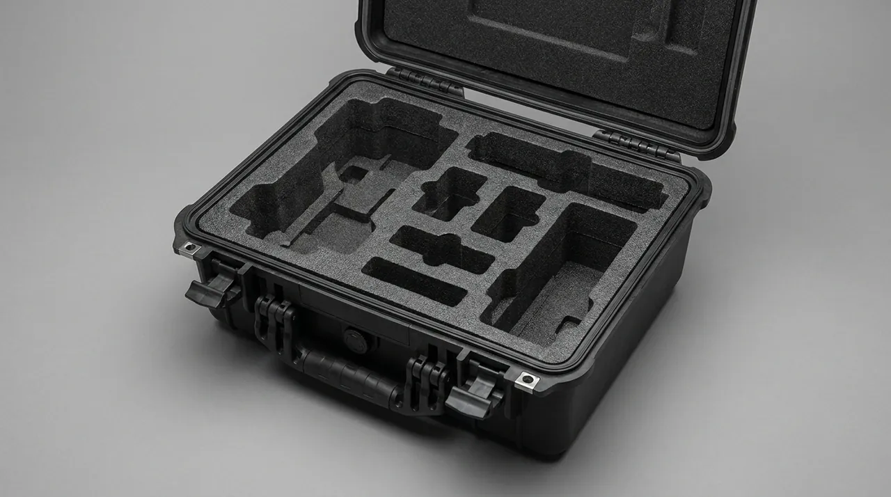
EVA foam is inexpensive, easy to machine and tough, making it a good pocket material for medium and low load parts. XPE foam is lower density with better resilience and works well as a surface cushioning layer. Polyurethane foam is dense, abrasion resistant and tear resistant, making it the first choice for pockets and saddles carrying heavy components. EPP and EPE serve applications needing longer compression travel and high rebound. For load-bearing saddles specifically, it is worth bonding a higher-hardness engineering plastic or plywood load plate on top of the foam so that weight is routed into the case wall.
| Material | Density range (kg/m3) | Compressive strength | Compression set | Typical location |
|---|---|---|---|---|
| --- | --- | --- | --- | --- |
| EVA | 60 - 120 | High | Medium | Medium part pockets, dividers |
| XPE | 25 - 45 | Low | Low | Surface cushioning, facing |
| Polyurethane | 150 - 400 | Very high | Low | Heavy part saddles, support blocks |
| EPE | 20 - 40 | Low | Medium | Long travel cushioning, void fill |
| EPP | 30 - 90 | Medium | Low | Structural liner for reusable cases |
Cutting accuracy is the hidden threshold for heavy liners. The clearance between pocket and part should sit between 1 and 3 mm on each side. Too much clearance defeats restraint; too little makes loading difficult and risks scratching surfaces on entry. Pocket floors need finger slots for retrieval, and deep pockets need through-holes so that a part can be lifted with both hands.
After liner design is fixed, a physical trial fit is worth the time, followed by a 24-hour rest period and a compression set recheck. If any depression exceeds 10 percent of original thickness and does not recover, the material density or hardness was specified too low and a denser polyurethane should be substituted.
Sealing, Breather Valves and Salt Fog Exposure
Excavator parts are predominantly export items, so marine transit and coastal sites are the normal condition rather than the extreme one. Salt fog attacks unpainted metal far faster than inland air, which means case protection strategy should treat salt fog as the baseline duty.
For sealing, a silicone or EPDM gasket at Shore A50 to A65 with 25 to 35 percent compression is a sound starting point. Gasket grooves should be dovetail or rectangular, and corners must be moulded in one piece. A spliced gasket leaves a microscopic gap at the corner that becomes the primary water path. Latch quantity must match case size, typically one latch per 300 to 400 mm of edge length, with a metal reinforcement pad at each latch.
The general reference for salt spray testing is GB/T 10125, artificial atmosphere corrosion testing, salt spray test. The common neutral salt spray condition uses 50 g/L plus or minus 5 g/L sodium chloride at 35 degrees Celsius plus or minus 2 degrees. Where the corrosion resistance of case hardware such as latches, hinges and skeletons is being assessed, a 48 to 96 hour acceptance line with no red rust is reasonable; long ocean freight projects may tighten this to 240 or 480 hours. It must be stated clearly that salt spray duration does not convert simply into outdoor service life. It is a comparative tool between design options.
The breather valve balances internal and external pressure. The better a case seals, the more pronounced the differential becomes: containers swing in internal pressure with day-night temperature cycles, and a fully sealed rigid case can be hard to open under negative pressure or can push its gasket out of the groove. Valved cases should use a venting-but-waterproof structure with a membrane pore size between 0.1 and 1 micrometre, blocking liquid water and dust while allowing air to pass.
A common misunderstanding is to treat the breather as a drain. The two functions are entirely different. A drain discharges accumulated liquid, must be one-way and sits at the lowest point; a breather handles air exchange and normally sits high or on the side. Confusing them destroys the sealing system.
Transport and Environmental Test References
Testing of the case and contents assembly falls into three families: sealing, environmental adaptation and transport dynamics.
Sealing follows IEC 60529, equivalently GB/T 4208, for IP rating verification. IP67 requires complete dust protection and no ingress after short-term immersion, while IP68 covers deeper continuous immersion. Before testing, the case interior should be confirmed free of liquid and the gasket checked for twisting.
Environmental adaptation can be drawn from MIL-STD-810H methods, including high temperature, low temperature, thermal shock, humidity, vibration and shock. It should be stated plainly that citing MIL-STD-810H means only that test methods and environmental conditions are taken from that standard to verify product behaviour in those conditions. It is not a military certification and confers no military qualification of any kind. The standard's value in industrial protective cases is that it provides reproducible conditions and pass criteria, which lets buyer and supplier agree an acceptance baseline in contract. A fuller explanation is available in MIL-STD-810H environmental test reference.
For transport dynamics, the domestic reference is the GB/T 4857 series of basic tests for transport packages, covering vibration, shock, drop and stacking. International logistics can refer to ASTM D4169 distribution cycle simulation, selecting the appropriate cycle and assurance level for the actual route. Test elements are described in GB/T 4857 transport packaging test methods.
For hydraulic components, one additional item belongs in the test plan: a plug integrity check. After vibration testing, all port plugs should be sampled for airtightness, at a sampling ratio of at least 10 percent. This check is not mandatory in most standards, but it carries high practical value in preventing hydraulic failures.
Outbound Inspection and Sampling Judgement
The most common weakness at acceptance is relying on visual appearance and feel. Appearance only reveals visible damage, and feel cannot quantify whether restraint meets design intent. Splitting acceptance into five checkable actions is more reliable.
First, verify the packing unit list against the loading drawing, confirming part numbers, quantities and specifications. Second, check restraint condition on every item: hand pressure should not move a part more than 1 mm, and after lifting one end of the case to 30 degrees the movement should stay under 2 mm. Third, inspect precision surfaces: piston rod coatings, cylinder bores, pin journals and adapter interfaces must show no scoring, indentation or flash rust. Fourth, check plugging and cleanliness: confirm every port plug and dust cap is present, and that no oil has spread across the liner. Fifth, check marking and documentation: plug list, remove-before-installation tags, packing list, certificate of conformity and any material or test documents available under contract.
Sampling judgement should follow the counting inspection logic of GB/T 2828.1, with sample size and acceptance number derived from lot size and AQL. For heavy, high-value items, a zero-sample pass is rarely appropriate. A more defensible arrangement is full inspection for critical characteristics such as sealing, coating integrity and plugging, and sampling for secondary characteristics such as label placement and cosmetic finish. Sampling and acceptance flow is described in custom case acceptance and AQL sampling.
Where traceability is required, assign a unique case number and bind it to the packing record. That record should include at minimum the packing date, packer, verifier, liner drawing number and test report number, so that any later claim can be traced quickly to design, material or workmanship.
Frequently Asked Questions
Q: Can an excavator bucket ship in a timber crate alone, or is a steel skeleton always required?
A: The decision rests on bucket mass, centre of gravity location and transport mode together. As a working guideline, a standard digging bucket under about 800 kg empty with a centre of gravity near the geometric middle can travel in a fumigation-free plywood crate of adequate thickness with full-face base support. Above that range, or for rock buckets and skeleton buckets with offset centres of gravity, steel or glass-fibre reinforced skeletons should be added at the corners and long edges. The reason is that timber crates rarely fail through panel strength; they fail at corner joints sheared apart by repeated sway. Containerised ocean freight adds further dynamic load, and a static safety factor of 3.5 or above is advisable. A simple check is to multiply design load by the dynamic factor and confirm the crate floor beneath the support face will not deflect permanently. When in doubt, a steel skeleton case costs more but avoids a single claim that would wipe out many savings.
Q: Since bucket teeth are replaced often, is dedicated pocketing really necessary in transit?
A: Yes, and it deserves more attention than the bucket body itself. The teeth have low unit value, but the problems sit at the adapter and pin bore. Tooth and adapter form a tight fit that transmits digging force through mated faces. If teeth are strung together or loaded loose beside the bucket, impact raises burrs on the adapter interface so the tooth cannot bed down. A tooth that cannot seat tightly will chatter under load, and repeated cycling converts that chatter into fretting wear and eventually a crack initiation site at the adapter root. The adapter is part of the welded bucket structure, so replacing it requires cutting and rewelding, a far greater cost than the tooth itself. The disciplined method is one tooth per dedicated pocket with consistent tip orientation, tooth bodies flanked by liner material and the tip zone left clear. Where teeth ship already fitted to the bucket, each one should receive a polyurethane cap at Shore A60 to A75. The incremental cost is modest and the reduction in early field failures is substantial.
Q: How deep a score on a piston rod coating means the cylinder must be scrapped?
A: Depth alone is not the deciding parameter. Location, orientation and raised lip condition matter more. A score inside the stroke envelope running perpendicular to travel can cut the seal lip open even at a few micrometres depth, producing continuous weeping, and such rods are generally replaced. A score outside the stroke envelope with no raised lip can often be locally polished and returned to service. The genuinely dangerous case is a score with a raised lip, because that lip behaves as a micro cutting tool that shaves the rod seal once assembled. A practical check is to run a fingernail across the score at right angles. If the nail catches noticeably, a raised lip exists and the rod should be scrapped. Judgement must be completed immediately on unpacking and photographed for the record, because once assembly begins, responsibility becomes hard to establish. For volume deliveries, a full-length visual and tactile check before packing, recorded in the packing log, is worth building into the process as the basis for dividing transit liability.
Q: Are plastic caps sufficient for plugging hydraulic ports during sea freight?
A: For ocean freight, plastic dust caps alone are usually insufficient. Their primary purpose is blocking dust and foreign objects, and their resistance to moisture and salt fog is limited. They are also retained by elastic compression, which loosens under thermal cycling and vibration. Container interiors can swing more than 20 degrees Celsius between day and night, and repeated expansion and contraction creates a breathing effect that can draw humid air past microscopic gaps at the plug, producing pitting on cylinder bores or spool surfaces. The more dependable method is a metal threaded plug, wrapped with an appropriate amount of PTFE tape and torqued in place, giving both mechanical and thread sealing. External ports should then receive a dust cap as a second layer. A plug list should travel inside the case, with a remove-before-installation tag fixed to the lid interior or another conspicuous position. For main control valves and pumps with tighter cleanliness requirements, an airtightness sample check after plugging is worth adding, at a ratio set by lot and contract, typically at least 10 percent.
Q: Does an excavator parts case need IP67, or is dust protection enough?
A: The answer depends on component sensitivity and the logistics chain. Pins and bushings, which receive additional rust prevention later and tolerate some moisture, are well served by dust protection, with the focus on foreign object exclusion and impact protection. Hydraulic cylinders, valve blocks and motors, which contain precision fits that are difficult to clean again on site, justify IP67 on the primary gasket, meaning no ingress after 30 minutes at 1 m immersion verified to IEC 60529. Beyond component sensitivity, consider the route: open storage at terminals, inland transhipment and road movement through wet regions all raise the marginal value of better sealing. It is worth noting that IP67 is not a single attribute. It depends simultaneously on case structure, gasket material and compression, latch count and preload. Common failure causes are spliced gasket corners, excessive latch spacing and insufficient preload. Sealing grade should therefore be confirmed together with the use case, and a sample case should actually be immersion tested rather than judged from material data alone.
Q: For heavy excavator parts, is a custom liner or a pour-in-place liner the better choice?
A: For heavy parts, a custom liner is almost always the better choice. Pour-in-place offers fast fitment and low initial cost, and suits simple shapes, low mass and small batches. Its weaknesses are that density and hardness distribution cannot be controlled and the foam creeps markedly under sustained heavy load, forming a depression beneath the part over time so that restraint is lost. The core value of a custom liner is the ability to design a material gradient along the load path: high-density polyurethane where load is directly carried, EVA in transition zones, and XPE or flocked surfacing at the contact layer, converting point contact into area contact and routing weight into the case wall. A custom liner can also be moulded in one piece with pockets, finger slots, dividers and hold-down features, so it is ready to load on arrival without depending on site fabrication capability. For excavator parts with fast dispatch cycles and limited tooling on site, that matters. The cost difference appears mainly at tooling and sampling stage; in volume, unit cost amortises while the reduction in rework and claims generally covers the initial investment.
Q: How long should a salt spray test run, and is 48 hours enough?
A: Test duration follows the service environment and the purpose of comparison, not a universal number. For products aimed at inland sites and short road movements, 48 hours of neutral salt spray is enough to expose obvious coating or plating defects and serves as a basic threshold. Where ocean freight or long coastal storage is involved, tightening to 240 hours with no red rust on hardware such as latches, hinges, skeletons and rivets is advisable. For high-value, long-life projects, 480 hours can be run to assess greater margin, accepting the cost and lead time. Conditions follow the salt spray portion of GB/T 10125 artificial atmosphere corrosion testing, typically neutral salt spray at 50 g/L plus or minus 5 g/L sodium chloride and 35 degrees Celsius plus or minus 2 degrees. It must be stressed that salt spray duration does not convert simply into outdoor service life, because outdoor exposure also involves wet-dry cycling, ultraviolet radiation and deposited pollutants. Its correct use is to compare material or process options on the same product, or to serve as an agreed acceptance baseline. The standard, conditions, duration and pass criteria should therefore be written into the contract technical annex to avoid disagreement at acceptance.
Q: What are the risks of shipping bucket accessories and hydraulic components in one case?
A: Three families of risk arise, and all of them surface later in service. The first is mechanical: heavy castings shift under vibration and strike precision hydraulic surfaces, and damage to a piston rod coating or cylinder bore is irreversible. The second is contamination: castings typically carry rust preventive oil, sand dust and moulding sand residue, all of which disperse in a vibrating case and settle on hydraulic surfaces, later entering the hydraulic system as abrasive particles. The third is oil exposure: if a hydraulic port plug fails in transit, escaping oil contaminates the rust preventive layer on the castings and undermines the protection system. Where mixed loading is unavoidable for logistics reasons, three minimum measures apply: a rigid divider must fully isolate the two zones with independent sealing; all castings must be cleaned before loading to remove loose sand and excess oil; and hydraulic components must be individually wrapped in vapour phase inhibiting film before being placed. Even then, separate cases remain the recommended arrangement, particularly when the shipment includes high-value precision items such as main control valves and hydraulic pumps.
Conclusion and Related Reading
The design intent behind an excavator parts case always reduces to the same three rules: keep heavy items from generating impact, keep precision items from touching hard objects, and keep moisture-sensitive items away from salt-laden air. Grade buckets by type and tonnage, pocket each tooth individually, saddle cylinders on curved supports with double-plugged ports, preserve pins and bushings with vapour phase film, verify case load class and sealing against the real logistics chain, and then prove the design assumptions with salt spray, vibration and immersion testing. JUNZHIJIA, manufactured by Kexin New Materials (Guangdong) Co., Ltd., provides a complete package for earthmoving parts protection, from liner design and case moulding through OEM and ODM customisation, serving wholesale, agency and global supply customers, with material certificates and test documents available under contract. For selection support, provide bucket capacity or component drawings, centre of gravity location, individual mass and destination port so that case type, liner configuration and test plan can be issued in one pass.
Related Reading