

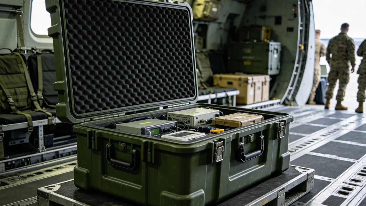
Protecting wheel loader components in transit is not a question of whether a case is big enough. It is a question of handling two component families whose mechanical behaviour has almost nothing in common. The loader bucket is a thin-shell welded structure with a cutting edge, vulnerable to edge rolling and permanent deformation of the bottom shell. The torque converter, transmission and axle are sealed precision assemblies, vulnerable to loss of bearing preload and seal lip eccentric wear when transport locking is missing. Three rules frame the answer: a loader bucket must be supported according to edge type and capacity, and its cutting edge must never bear load downward; converter and transmission assemblies need external locking devices fitted before packing, shipped with the part and tagged for removal; and drive axles must be supported on housing faces or dedicated lugs, never on half shafts or brake chambers. Compared with a tracked excavator, a wheel loader carries a whole road-drive chain, which means more parts, heavier individual pieces and assemblies that are far harder to inspect once installed.
When a wheel loader is exported, it normally ships as separate consignments covering the attachment, the drive assembly, the cab and the frame. The drive assembly accounts for a high share of total component value and contains seals, bearings and friction plates that require major repair the moment they are contaminated or run eccentrically. Many claim cases do not start with an under-strength case at all. They start with a locking device that was never fitted, or was fitted but never removed on site, or was removed without the correct reinstallation sequence. The sections below follow that chain from end to end, covering edge protection, drive locking, support layout, liner selection, sealing and rust prevention, and acceptance testing, so that machine builders, parts distributors and third-party logistics providers can use them directly when drafting a packaging technical agreement.
Table of Contents
- Selection Logic and Application Boundaries
- Identifying Cutting Edge and Bottom Shell Structure
- Edge Protection for Cutting Edges and Wear Plates
- Transport Locking for Converter and Transmission
- Phase Retention for Drive Shafts and Universal Joints
- Heavy-Duty Support for Drive Axles and Wheel Ends
- Securing Work Equipment Cylinders and Boom Parts
- Verifying Case Bearing Faces and Lifting Points
- Liner Hardness Gradients and Creep Resistance
- Dust, Water and Rust Prevention Across the Case
- Test Matrix: Vibration, Drop and Salt Spray
- Packing Work Instructions and Acceptance Records
- Frequently Asked Questions
- Conclusion and Related Reading
Selection Logic and Application Boundaries
Selection begins by classifying the contents as either a structural part or an assembly. Structural parts such as buckets, booms, linkages and brackets fail by deformation and impact, so the protection priority is bearing faces and edges. Assemblies such as torque converters, transmissions, axles and cylinders fail by internal displacement, eccentric seal wear and contamination, so the priority is locking and sealing. The two failure modes need two different design languages, and they cannot share a single packing approach.
Application boundaries also need fixing early. Bucket capacities on wheel loaders commonly run from 1.5 to 4.5 m3 with empty masses between 900 and 2600 kg. At that scale a conventional protective case is no longer sensible for the bucket itself, and a cradle with a removable hold-down beam is the better answer, with cases reserved for machines at 1.8 m3 and below. A transmission assembly, by contrast, may weigh over 1000 kg yet remains an ideal case candidate: it has lifting eyes, a regular outline and clearly defined bearing faces. It is often the component type best served by a heavy timber crate or steel skeleton case.
The third judgement is installation timing. If the destination is a machine builder's assembly line, where components move quickly onto the line, the packing design can be trimmed because exposure time is short. If components go into a parts warehouse for long-term stock, especially in hot and humid export regions, liner specification, vapour phase protection and sealing grade should all move up one tier. This call belongs in the quotation stage, because retrofitting it later raises cost sharply. Review criteria for OEM and ODM engagements are covered in choosing a custom case factory.
Field observation: in wheel loader claim records, direct losses from a ruptured case are modest. Most losses come from hidden failures where the case arrives intact but the component inside is already damaged, and those are very hard to detect at unpacking.
Identifying Cutting Edge and Bottom Shell Structure
Loader buckets differ structurally from excavator buckets in one fundamental respect. Almost all loader buckets use a single continuous cutting edge to penetrate the pile rather than a set of teeth, with a bottom wear plate or grate behind the edge. This layout concentrates transit vulnerability in two places: cutting edge straightness and bottom shell flatness.
The cutting edge is usually high-hardness wear-resistant steel, 20 to 40 mm thick, with hardness reaching HB 400 or above. High hardness means wear resistance without bending resistance, so once the edge is backed against the case floor or another hard object, it bends locally near the load point. The result after installation is higher penetration resistance, uneven entry into the pile and steps left on graded surfaces. The edge should therefore face up or sideways, with a continuous support strip beneath it made of material softer than the edge, typically polyurethane or hardwood.
The bottom shell is usually a thin shell with a wear liner and has poor resistance to local puncture. Packing must ensure the shell rests on a full-area liner rather than on fork tines or support blocks that create point contact. On models with bottom grates or screen bars, the grate edges are the most snag-prone feature and need edge strips, because a snagged sling during lifting can end in a dropped bucket.
| Loader bucket type | Edge configuration | Typical capacity | Empty mass (kg) | Recommended support and restraint |
|---|---|---|---|---|
| --- | --- | --- | --- | --- |
| General purpose bucket | Straight edge with bottom wear plate | 1.5 - 2.5 m3 | 900 - 1500 | Full-area liner, edge guard strips, two hard limiters |
| Rock bucket | Thickened edge with adapters | 1.8 - 3.0 m3 | 1300 - 2100 | Steel skeleton cradle, four hard limiters, tooth guards |
| Light material bucket | Thin edge, large volume | 2.5 - 4.5 m3 | 1000 - 1800 | Light cradle, side guards, anti-roll hold-down |
| Push bucket | Raised back plate with push frame | 2.0 - 3.5 m3 | 1400 - 2200 | Cradle, top hold-down beam, plate corner guards |
| Quick coupler bucket | General edge with coupler interface | 1.5 - 3.0 m3 | 1100 - 1900 | Cradle, plugged coupler interface, separate guard |
Quick coupler buckets and couplers deserve separate mention. Their hydraulic interfaces and mechanical jaws are exposed, and once the jaw pin bores are burred, on-site assembly may bind or leave excessive play. Jaw pin bores should be filled with protective plugs before dispatch, and the hydraulic interface plugged and capped.
Edge Protection for Cutting Edges and Wear Plates
Edge protection rests on making sure the cutting edge touches nothing of equal or greater hardness. Three layers deliver this: continuous support, soft wrapping and orientation control.
Continuous support means a full-length support strip beneath the edge, at least 80 percent of edge length and three times the edge thickness in width. Soft wrapping means guard strips at both ends and at intermediate load points, in polyurethane at Shore A75 to A90 or laminated hardwood. Material harder than the edge would damage the edge in reverse. Orientation control means all edges face the same way, and no case should contain two buckets with edges facing each other.
Bottom wear plates and bottom liners are consumable items bolted or welded to the shell. They are not fragile in themselves, but their bolt heads protrude and press into the liner. The right answer is a recess at each bolt head rather than simply compressing foam over it, because sustained static pressure forms a depression that will not recover and routes concentrated load into the liner.
On rock buckets fitted with teeth, the adapter deserves higher protection priority than the tooth. The adapter is welded to the cutting edge and requires cutting and rewelding to replace, while the tooth is a plug-in wear item. Adapter-driven positioning is therefore the right approach: one dedicated pocket per adapter position, support under the adapter and the tooth tip left free.
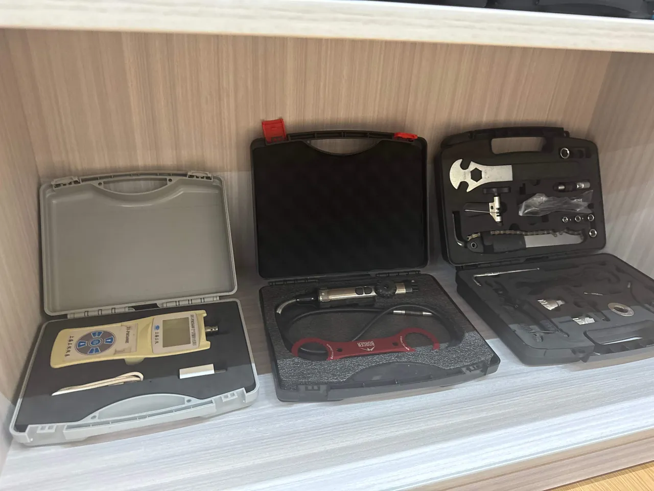
Purchased buckets and original machine buckets often differ in structure, particularly edge thickness and bolt hole layout. Liner design should start from physical samples or three-dimensional data rather than capacity estimates. Edge treatment logic for castings and welded structures follows the approach described in construction machinery structural and cast part packing.
Transport Locking for Converter and Transmission
Torque converters and transmission assemblies carry the highest value and the greatest hidden-damage risk in the wheel loader drive chain. Both contain rolling bearings, seals and friction plates. Without external locking in transit, the input or output shaft makes small reciprocating movements under vibration. These movements are not large enough to damage parts directly, but they alter bearing preload and leave eccentric wear marks on seal lips. Eccentric wear stays invisible for the first few hundred hours after installation, then manifests as weeping.
Locking works in three steps. First, choose the locking point by assembly structure. Common practice is a locking plate between output flange and housing, or a locating sleeve between input shaft and housing. Second, the locking device needs enough stiffness to withstand repeated random vibration loads without yielding. A practical design target is a static capacity of 0.3 to 0.5 times assembly mass. Third, the locking device ships with the part and carries a tag stating that it must be removed before installation, along with the removal sequence.
Ports and breathers need equal attention. A transmission breather on the top cover should be removed and replaced with a plug, with the breather bagged and shipped with the part. In a well-sealed case, thermal cycling generates pressure differential, and a breather left open will vent oil mist outward as internal pressure changes, contaminating the liner and coating the interior in an oil film while also drawing in humid outside air.
| Drive component | Locking point | Recommended device | Removal stage | Consequence if missed |
|---|---|---|---|---|
| --- | --- | --- | --- | --- |
| Torque converter assembly | Output flange to housing | Steel locking plate with bolts | Before machine entry | Bearing preload change, early weeping |
| Transmission assembly | Input or output shaft | Locating sleeve and end plate | Before drive shaft connection | Seal eccentric wear, idle noise |
| Drive axle assembly | Housing lug or half shaft end | Support frame with strapping | Before axle installation | Half shaft bending, wheel end runout |
| Drive shaft | Both end flanges | Phase retention fixture | Before flange mating | Balance loss, high speed vibration |
| Wet brake | Brake piston cavity | Process plug | Before hydraulic connection | Cavity contamination, brake drag |
One further note on friction plates and wet brakes: these are extremely sensitive to foreign objects, and a single grain of sand in the friction pair can cause scoring and brake drag. Every hydraulic passage leading to a friction pair must therefore be closed with a process plug during transit, and the plug should carry a seal rather than relying on thread engagement alone.
Phase Retention for Drive Shafts and Universal Joints
The drive shaft is the component most casually handled on a wheel loader, because it looks like nothing more than a steel tube. In reality it is a dynamically balanced assembly whose two universal joints stand in a defined phase relationship. Both balance loss and phase error show up as vibration in the mid and upper speed ranges after installation.
Two methods retain phase in transit. The first uses a dedicated phase fixture locking both yokes at the designed relative angle, shipped with the shaft. The second uses strapping to fix each yoke in its own pocket, with the relative angle between pockets noted on the packing drawing. Both methods share one requirement: the shaft must never be single-point supported, and needs at least three support points including one at mid-span.
Splines and splined sleeves are another weak point. Spline surfaces normally carry lubricating grease under a rubber boot. A torn boot lets sand and dust adhere to the grease and form an abrasive paste that accelerates spline wear once installed. The practice is to wrap the spline boot in vapour phase inhibiting film and place the whole shaft in its own isolated cavity.
For storage attitude, a horizontal shaft with the slip joint facing up or sideways is preferred. A vertical shaft lets its own weight pass through the splines into the slip joint end face, and long-term static loading can create local bearing stress on the splines. Where case dimensions force an angled position, the angle should stay under 15 degrees with a support at the lowest point.
Adjacent components on the same drive train share this positioning logic. Shaft alignment retention and end face protection for coupling type parts are described in shaft coupling and drive train positioning.
Heavy-Duty Support for Drive Axles and Wheel Ends
A drive axle assembly typically comprises housing, differential, half shafts, wheel end reducers and brakes, and can exceed 1500 kg. It is among the heaviest single items a wheel loader parts case must handle. The support logic is simply this: load must pass into the case through housing structural faces, and under no circumstances through half shafts, brake chambers or hydraulic fittings.
Support faces are normally taken at the housing lower edges or cast lugs at both ends. The case interior needs two saddles matching housing outline, with curved faces contacting the housing outside diameter over a contact angle of at least 110 degrees, and load transferred below through high-density polyurethane or laminated timber. Saddle positions should sit as close to the wheel ends as possible to reduce bending moment at housing mid-span.
Exposed lines and sensor harnesses at wheel end reducers and brakes must be secured or sleeved rather than left hanging. A stretched sensor harness can break internal signal wires, which then appear as intermittent alarms after installation, and fault tracing is expensive.
Where a complete axle ships with inflated tyres, pressure usually needs reducing to a specified transport value, with the tyre condition and re-inflation requirement noted inside the case. Wheel ends with exposed tyres and brake drums should be fitted with guards to keep fork tines away.
Case lifting points must align with assembly centre of gravity. Because the differential is offset, an axle assembly rarely has its centre of gravity at mid-span, so lifting points should bias toward the heavy side. Otherwise the case tilts on lift and the contents shift. Lifting point positions should be permanently marked on the case with a stamp or weather-resistant label, not merely recorded in the shipping documents.
Load class verification and skeleton requirements for heavy parts follow a common approach, and the treatment of saddle layout and lifting point offset in axle and housing component transport protection applies directly here.
Securing Work Equipment Cylinders and Boom Parts
Wheel loader work equipment cylinders include boom and bucket cylinders, with long strokes, large bores and long exposed rod sections. They are high-risk items for coating damage in transit.
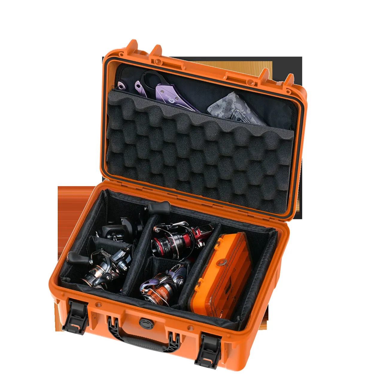
Four requirements apply. First, rods stay fully retracted; where structure prevents this, the exposed length must be sleeved in full. Second, cylinders sit horizontally or near-horizontally on curved saddles matching barrel outside diameter. Third, ports receive dual plugging, meaning a threaded plug plus a dust cap, with neither optional. Fourth, pins and spherical bearings removed from the cylinder are packed separately and never share a cavity with the barrel.
Booms and linkages are long cantilever structures vulnerable to bending and pin bore damage. The bend section of a boom is a stress concentration zone, so supports belong on both sides of the bend rather than leaving a long overhang. Linkage pin bores are usually machined and need a matched process plug, ideally in engineering plastic rather than metal, so that the bore wall is not scratched.
A detail easily overlooked: if cutting fluid or cleaning agent remains in a boom or linkage pin bore, marine humidity will produce corrosion spots on the bore wall. When the pin is pressed in during assembly, those spots are crushed into hard particles that enter the spherical bearing and accelerate wear. Bore drying and temporary rust prevention before packing are therefore essential steps.
Cleanliness requirements for hydraulic systems at delivery match those for machine assembly, particularly on machines with proportional valves or load sensing systems. Port plugging and cleanliness control for hydraulic components are described in pump and valve hydraulic component protection.
Verifying Case Bearing Faces and Lifting Points
Case verification covers two things: bearing face pressure and lifting point strength. Both are routinely skipped, and both are leading causes of heavy case failure.
Bearing face pressure verification divides contents mass by actual contact area to give mean pressure, then compares it with the allowable compressive stress of the liner material. Low density foams typically allow 0.05 to 0.15 MPa, high density polyurethane can exceed 0.5 MPa, and timber in the parallel direction can reach several MPa. If calculated pressure exceeds the allowable value, sustained static loading will produce irreversible compression and restraint will be lost. The fix is not thicker foam but a load plate inserted at the bearing point.
Lifting point strength must include a dynamic factor. The instantaneous factor at lift-off is normally taken as 2 or higher, and increases further for lifts with impact risk such as lowering from a height. Lifting points belong on the primary structural beams rather than on panels, and bolted connections need backing plates to spread load. Self-tapping screws must never be used to attach lifting eyes.
| Verification item | Input parameters | Pass criterion | Typical failure mode |
|---|---|---|---|
| --- | --- | --- | --- |
| Bearing face pressure | Part mass divided by contact area | Within liner allowable stress | Liner collapse, restraint lost |
| Lifting point strength | Mass times dynamic factor of 2 or more | Beam stress within allowable | Lifting bolt pull-out, case tearing |
| Case floor deflection | Concentrated load position and span | Irreversible deflection under 2 mm | Floor bulging, contents shifting |
| Stacking stability | Layers and eccentricity | No toppling under offset load | Upper case sliding off |
| Fork entry | Tine spacing and depth | Load plates aligned with tine path | Bottom liner punched through |
For packaging units that will be stacked, centre of gravity offset should stay within 10 percent of case width. Where this is exceeded, either add ballast or restrict to a single layer. Stacking diagrams and layer limits belong printed on the case side rather than left to operator judgement.
Liner Hardness Gradients and Creep Resistance
A wheel loader parts case must accommodate components with wildly different hardness inside one box: dense cast steel parts alongside thin guards and harnesses. A single-hardness liner cannot serve both, so a hardness gradient is required.
Gradient design works by layer along the load path. The bottom layer is the load-bearing layer in high-density polyurethane or laminated timber, routing weight into the case wall. The middle layer is the pocket layer in medium-density EVA, providing shape restraint. The top layer, in contact with the component, is a cushioning layer in XPE or flocked material, protecting surfaces and absorbing micro-vibration. A practical thickness split across these three layers is 3:4:3, adjusted for specific part geometry.
Creep resistance is the key metric for heavy liners. A lower compression set means more stable long-term restraint. Testing follows the compression set method for the material, measuring thickness recovery after a defined period at 25 percent compression. As a working reference, high-density polyurethane should show compression set below 5 percent at 70 degrees Celsius over 22 hours, while ordinary EVA typically falls between 10 and 20 percent under the same conditions.
Anti-slip treatment between liner and case is also needed. The liner base should carry an anti-slip pattern or be bonded with double-sided tape so the whole liner cannot slide. Liner displacement is a frequent nonconformance in packaging units that go through vibration testing.
Moulding processes and interlayer bonding requirements for multi-layer composite liners are described in custom EVA insert moulding process, including hot pressing, splicing and adhesive weathering.
Dust, Water and Rust Prevention Across the Case
Wheel loader components are predominantly metal and include many unpainted machined surfaces. The rust prevention system should work at two levels: component level and case level.
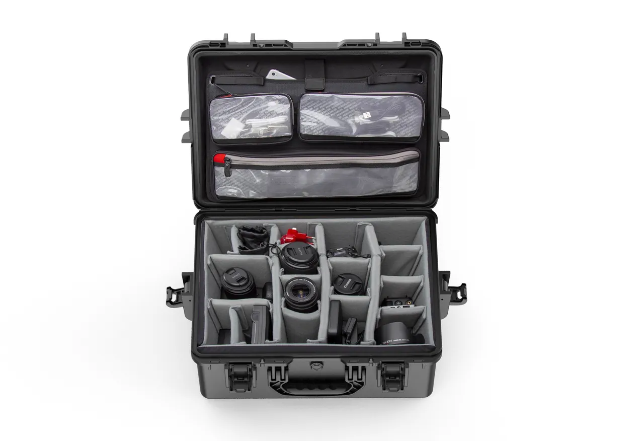
Component level measures include rust preventive oil or grease on machined faces, vapour phase inhibiting film around small parts, and process plugs protecting pin bores and ports. Compatibility between rust preventive oil and liner material matters, because some foams absorb the oil and thin the film, so a barrier film between liner and oiled surface is advisable.
Case level measures include sealing, breather valves and desiccant. Sealing grade follows transport mode and destination port environment. For long ocean voyages, IP67 on the primary gasket is advisable, verified to IEC 60529 or the equivalent GB/T 4208, with a suitable quantity of desiccant inside. Desiccant quantity depends on contents volume and packaging barrier class, and a common starting estimate is 50 to 100 g of absorption capacity per 0.1 m3 of internal net volume, subject to confirmation by packaging integrity testing.
A breather valve equalises pressure without admitting liquid water. Selection must consider membrane pore size, airflow and cracking pressure, and the mounting position must avoid areas where water can pool. Structural detail and verification methods for sealing components are covered in achieving waterproof case IP ratings.
One caution: vapour phase protection and sealing are not cases where more is always better. A fully sealed case subjected to thermal cycling develops sustained differential pressure that repeatedly compresses and deforms the gasket, shortening its life. The correct arrangement lets the breather handle differential pressure while the gasket only blocks water and dust.
Test Matrix: Vibration, Drop and Salt Spray
Testing a parts case should cover three duty families: transport dynamics, environmental corrosion and sealing integrity. A matrix is better than isolated single tests, because real failures usually result from two factors acting together.
For transport dynamics, the domestic reference is the GB/T 4857 series of basic tests for transport packages, while international logistics can follow the ISTA series or ASTM D4169. For packaging units containing precision drive components, vibration testing should use a random spectrum rather than fixed frequency, because random vibration better represents real vehicle input. Selection logic and pass criteria for ISTA procedures are covered in ISTA transport test procedures. Drop height follows transport mode and packaging unit mass: for heavy items a lower drop height is not automatically safer, and the criterion must be the worst realistic handling event.
For environmental corrosion, the reference is the salt spray portion of GB/T 10125 artificial atmosphere corrosion testing. Acceptance lines for metal parts and case hardware should be set by destination environment: inland transport at 48 hours with no red rust, ocean freight at 240 hours, and long coastal storage tightened to 480 hours.
For sealing integrity, beyond IP immersion testing it is worth adding a whole-case airtightness check, measuring pressure decay rate after pressurising or evacuating the case. The advantage is that it confirms sealing system integrity without opening the case, making it ideal as the final pre-shipment check.
Matrix design should follow a worst-case combination principle. For example, "full load plus stacking plus random vibration plus high temperature and humidity" as one group, rather than testing each factor separately and adding the conclusions. Only then does the result carry engineering meaning.
Packing Work Instructions and Acceptance Records
A significant share of heavy parts case failures happens at the packing station rather than at the design desk, which is why a packing work instruction matters as much as a drawing.
The instruction should cover at least seven items: loading sequence, position and orientation of every item, locking device location and torque, plug list, liner inspection points, tightening sequence, and post-packing self-checks. Tightening sequence is often neglected. On multi-point hold-down cases, force should be applied symmetrically from the centre outward, because tightening one end first lifts the liner at the other end and defeats subsequent clamping.
Self-check items should be standardised at five: contents displacement, locking devices fitted, plugs fitted, liner condition, and marking and documentation. Every item needs a decidable criterion rather than an untraceable note such as "visually normal".
Acceptance records should support traceability. Assign a unique case number and bind it to the packing record, liner drawing number, test report number, packer and verifier. For export batches requiring customs clearance, the packing unit list should also be cross-checked against commercial invoice descriptions and quantities to reduce explanation effort during inspection.
For returnable cases used repeatedly, maintain a usage count and liner life record, because foam liners degrade gradually across cycles without obvious external signs. The full acceptance and sampling flow is described in custom case acceptance and AQL sampling.
Frequently Asked Questions
Q: Since loader buckets have no teeth, can edge protection be simplified?
A: It should be strengthened rather than simplified. A loader bucket edge is a continuous high-hardness wear-resistant steel bar whose function is to penetrate the pile, and straightness is critical to that function. An excavator bucket penetrates point by point through its teeth, so damage to a few tips is relatively local. A loader bucket with a locally bent or rolled edge loses the levelness of the entire edge line, which directly worsens penetration resistance and surface finish, and because the edge is welded or bolted on, replacement is costly and field straightening is impractical. Three rules therefore apply in transit: never bear load downward on the edge, always place a continuous support strip beneath it, and ensure the strip is softer than the edge. Polyurethane and laminated hardwood are the usual strip materials. Steel must never be used, and neither the case floor nor bare fork tines may contact the edge. In addition, no case should contain two buckets with edges facing each other, because relative movement in transit produces direct collision. On models with bottom grates, grate edges also need protective strips to prevent sling snagging during lifting.
Q: Must transmission locking devices ship with the part, or can they be fitted on arrival?
A: They must be fitted at the packing stage and shipped with the part, never left for the destination. The purpose of transport locking is to suppress vibration displacement throughout the journey, and the heaviest vibration exposure occurs on the road leg from the factory to the port and during port handling, both of which fall between packing and arrival. Fitting locking devices only at the destination means the entire high-load segment is unprotected, which defeats the purpose of a functional lock. Shipping the devices with the part serves a second purpose: it gives the on-site technician physical evidence that a component may still be locked. Without the physical device, there is no way to confirm whether the component travelled locked, and therefore no way to judge whether internal eccentric wear has already occurred. Recommended practice is to bag the locking devices, fix them to the case lid interior, and attach a tag listing the installation location, removal sequence and required torque, with the same information repeated in the packing list and shipping documents. Field experience shows that stating it in both the tag and the documents significantly reduces missed removals.
Q: Why should drive axle lifting points be offset rather than placed at mid-span?
A: Offsetting is required because a mid-span lifting point causes two problems. The first is lift tilt. An axle assembly's differential is usually clearly offset, and wheel end reducers and brakes are also asymmetric in mass, so the overall centre of gravity rarely falls at geometric mid-span. With a mid-span lifting point, the case tilts toward the heavy side on lift, and the tilt angle is amplified by inertia at the moment of lift-off, so contents shift and the carefully designed restraint becomes meaningless. The second problem is bending moment distribution. Even if the case does not tilt, a mid-span lifting point leaves unequal cantilevers on either side, significantly increasing bending moment in the heavy-side cantilever. Under prolonged suspended storage or long road vibration, that side of the case is more prone to fatigue. The correct method is to establish the centre of gravity by weighing or from the three-dimensional model, then place lifting points symmetrically about the vertical projection of that centre, usually as two or four points. Positions should be permanently marked on the case by stamp or weather-resistant label, not merely recorded in shipping documents, because rigging crews on site rarely read them.
Q: For wheel loader buckets, is a timber crate or a cradle more appropriate?
A: The dividing line is capacity and empty mass. As a working guide, loader buckets at 1.8 m3 and below with an empty mass under 1100 kg work well in a heavy timber crate with a custom liner. The crate's advantage is complete enclosed protection, which suits ocean freight and long-term storage. Buckets above 1.8 m3 or over 1100 kg empty are usually better served by a cradle with a removable hold-down beam, because achieving sufficient crate strength requires substantially thicker framing, which adds tare weight and volume and makes handling harder. A cradle is structurally efficient because support acts directly on the bottom shell and the edge support strip, and it is reusable. Whichever is chosen, three conditions must be met: full-area support rather than point contact, at least two hard limiters, and lifting points verified by calculation. For batches destined for long ocean voyages or humid regions, a cradle solution still needs separate vapour phase rust prevention on precision machined faces, because a cradle provides no enclosed environment.
Q: Why does liner creep resistance matter when nothing is visible from the outside?
A: Creep resistance differences are indeed invisible early on, and that is precisely the risk. A high compression set means the liner gradually thins under sustained pressure and does not recover, so restraint clearance grows. The process is progressive and may complete within days to weeks of packing, depending on load, temperature and material density. By the time the case is opened or the component installed, the contents already have movable play. Damage may not yet have occurred, but the latter part of the transit cycle was unprotected. Two metrics help. The first is the material compression set: at 25 percent compression, 70 degrees Celsius and 22 hours, high-density polyurethane should typically stay below 5 percent while ordinary EVA often falls between 10 and 20 percent. The second is physical verification: run a trial fit before shipment, rest it for 24 hours and check whether liner depressions exceed 10 percent of original thickness. If they exceed that and do not recover, density or hardness was specified too low and a denser material should be substituted.
Q: How important is drive shaft phase retention, and what happens without a fixture?
A: Its importance scales directly with shaft speed. On a shaft with two universal joints, the yokes at either end stand at a designed relative angle that determines whether the velocity fluctuations generated by the joints cancel each other. Once that phase relationship is disturbed, the fluctuations no longer cancel, and periodic torque pulsation appears in the drive train. This pulsation is inconspicuous under low-speed high-torque working conditions, but shows up as pronounced judder and noise during road travel between sites, and over time it accelerates wear on the joint crosses and splines. The typical causes in transit are single-point support or casual stacking, especially bundling the shaft with other long components. The disciplined method is to lock both yokes with a dedicated phase fixture shipped with the shaft, or to place each end in its own pocket with the relative angle dimensioned on the packing drawing. The shaft also needs at least three support points, and single-point support is never acceptable.
Q: How much desiccant is enough for a sea freight case?
A: No fixed gram figure applies, because quantity depends on three variables: internal net volume, packaging barrier class and transit duration. A common engineering starting point is 50 to 100 g of absorption capacity per 0.1 m3 of internal net volume, but this is only a starting point and must be corrected for the moisture vapour transmission rate of the packing. Where the case reaches IP67 with reliable sealing, transmission rate is low and the lower end applies. Where the case is not sealed, or where a timber crate with relatively high moisture content is used, the upper end or more is needed. Timber moisture content deserves particular attention, because inadequately dried lumber releases moisture continuously at high sea freight temperatures and saturates desiccant quickly. A more dependable approach is to place a humidity indicator card in a visible position inside the case so that effectiveness can be judged at unpacking. That is far more useful than debating desiccant quantity afterwards. For hydraulic parts and precision machined faces, combining a humidity indicator with vapour phase inhibiting film is recommended.
Q: How does a whole-case airtightness check differ from an IP67 immersion test?
A: The two serve different purposes and cannot substitute for each other. An IP67 immersion test evaluates whether water enters under realistic immersion conditions, making it a watertightness verification to IEC 60529 or GB/T 4208, typically 30 minutes at 1 m depth followed by internal inspection. An airtightness check evaluates the continuity and integrity of the sealing system by pressurising or evacuating the case and measuring pressure decay rate, using the rate to detect leak paths. The difference is that immersion testing stays closer to real service conditions but its sensitivity to small leaks depends on immersion duration and differential pressure, while airtightness checking is more sensitive to small leaks, requires no case opening and does not wet the contents. That makes it especially suitable as a final full inspection before shipment. Practice is normally to run airtightness as the full check and immersion as a sampled verification, which secures batch reliability while controlling test cost and lead time.
Conclusion and Related Reading
Designing a wheel loader parts case comes down to moving an entire drive chain safely to the assembly line: cutting edges facing up on continuous support strips softer than the edge; converters and transmissions externally locked with devices shipped in place; drive shafts phase-retained on three or more supports; axles carried on housing faces with lifting points biased to the heavy side; cylinders retracted with dual-plugged ports; liners graded by load path with compression set under control; cases verified for bearing face pressure and lifting dynamic load; and the whole design proven by vibration, salt spray and airtightness data. JUNZHIJIA, manufactured by Kexin New Materials (Guangdong) Co., Ltd., supports wheel loader and earthmoving component packaging with custom liner design, case moulding and global supply for wholesale, agency, OEM and ODM customers, with material and test documents available under contract. For selection support, provide bucket capacity or assembly three-dimensional data, individual mass and centre of gravity, destination port and transport mode so that case type, liner configuration and test plan can be issued in one pass.
Related Reading