


The motor grader is the only earthmoving machine whose selling point is shaping accuracy. It does not chase excavation volume or push distance. It uses a moldboard to cut a surface to a designed elevation and crossfall. That functional identity means its critical components must be treated as precision parts in transit rather than as structural parts. Three criteria frame the protection logic. The moldboard is a long curved wear plate whose straightness is its functional datum, so it must be supported at evenly spaced points determined by deflection calculation rather than by rule of thumb. The circle and its gear ring are toothed mating components that must travel either fully meshed or fully disengaged, with no point loading ever applied through the teeth. The circle drive box and slide rail system contain worm gearing, sliders and clearance fits, so they must be locked before dispatch with removal sequence marked inside the case, and slide rail straightness deviation translates directly into longitudinal surface unevenness. A further issue is more pronounced on graders than on other machines: many components are long items between 1.5 m and 4 m, and long items fail by bending rather than by impact.
Across the chain from machine disassembly to parts warehousing, one step is most often neglected: support point placement. The same moldboard sags on two supports and sits stable on four evenly spaced ones. The same slide rail can deflect several times more on two end supports than with a mid support added. The difference is invisible at the packing station, but after installation it shows up as moldboard cross-level out of tolerance, slide rail binding or circle drive noise. The sections below follow moldboard, edge, circle, circle drive, slide rail, tilt linkage, packaging boundaries, liner, support calculation, corrosion protection and testing, turning each step into a calculable or checkable criterion.
Table of Contents
- Precision Protection Positioning for Grader Parts Cases
- Moldboard Curved Structure and Straightness Datum
- Edge and End Bit Cutting Alignment Protection
- Tooth Flank Protection for Circle and Gear Ring
- Locking the Circle Drive Box and Worm Gearing
- Straightness Retention for Slide Rails and Shift Cylinders
- Clearance Management for Tilt Linkage and Rods
- Case Size Boundaries and Split Packing Strategy
- Liner Design for Long Precision Items
- Support Spacing Calculation for Deformation Control
- Rust Prevention and Hydraulic Cleanliness Control
- Test Verification and Dispatch Records
- Frequently Asked Questions
- Conclusion and Related Reading
Precision Protection Positioning for Grader Parts Cases
Treating grader components as precision parts means doing three things first, and all three relate to measurement rather than to strength.
The first is defining functional datums. The moldboard datum is edge straightness and back-face curvature. The circle datum is gear ring pitch circle and face runout. The slide rail datum is guide face straightness and parallelism. These datums must be marked on the packing drawing so that packing staff know which faces may not carry load and which may not contact hard objects. A packing drawing without datum marks is equivalent to no drawing at all.
The second is setting allowable deformation. Moldboard straightness allowance is typically controlled at around one thousandth of overall length, meaning a 3 m moldboard allows deviation in the millimetre range. That is far tighter than the deformation tolerance of a structural part, so support layout must be calculated.
The third is choosing verifiable criteria. Deformation is invisible damage, and visual inspection at packing cannot detect it. Records covering support point positions, support face contact condition and post-packing re-measurement must therefore be introduced so that deformation risk is documented rather than assumed.
Putting these three in place depends on common inputs: a three-dimensional model or measured outline, individual mass and centre of gravity, a list of functional datum faces, and permitted deviation values. Without any one of them, liner and support design falls back to the most conservative option and cost rises noticeably. Methods for dividing and limiting long items inside a case are described in removable divider systems for long items, covering divider spacing and limiting methods.
A practical check on whether a grader parts case is acceptable: after packing, measure the height difference between the two moldboard ends relative to the case floor, rest for 24 hours and measure again. The difference between the two values should be less than one third of the allowable straightness deviation. If it exceeds that, support point layout or contact condition is wrong.
Moldboard Curved Structure and Straightness Datum
The moldboard is a large-radius curved wear plate with reinforcement ribs and slide rail mounting pads welded to its back face and a cutting edge bolted to its front. Its structural signature is a large radius, often between 500 and 900 mm, a moderate plate thickness of 12 to 25 mm, a large area and almost no flat surface.
The dominant transit failure is therefore a change in curvature rather than a local dent. Moldboard self-weight is distributed evenly along its length, so with too few supports the whole plate deflects as a simply supported or cantilever beam, sagging at mid-span or at the ends. Sag within the elastic range recovers on unloading, but prolonged static loading combined with stacking load converts part of it into permanent deformation. Curvature then no longer matches specification, penetration angle becomes uneven during grading, and the surface shows waves.
The first support principle is therefore evenly spaced multiple points, and the second is that support faces must match curvature. A support face must be a saddle matching the moldboard back curvature, not a flat pad. A flat pad on a curved surface produces line contact at the edges, where contact stress is far higher than in area contact, and creates local impressions instead of preventing them.
Rib locations are also preferred support positions. Reinforcement ribs on the moldboard back are high-stiffness regions, so supporting there routes load directly into primary structure, whereas supporting between ribs makes the face plate carry bending. The packing drawing should mark rib positions and map them to numbered support points.
| Moldboard specification | Typical length | Plate thickness | Empty mass (kg) | Suggested support points | Suggested packing |
|---|---|---|---|---|---|
| --- | --- | --- | --- | --- | --- |
| Standard moldboard | 2.4 - 3.0 m | 16 - 20 mm | 400 - 650 | 4 - 5 | Long cradle with curved saddles |
| Extended moldboard | 3.0 - 3.7 m | 16 - 22 mm | 550 - 850 | 5 - 6 | Long cradle with multiple saddles |
| Heavy duty moldboard | 3.7 - 4.3 m | 20 - 25 mm | 750 - 1200 | 6 - 8 | Steel skeleton cradle with top hold-down beam |
| Front moldboard option | 2.4 - 3.7 m | 16 - 20 mm | 350 - 700 | 4 - 6 | Long cradle with lateral limiters |
| Scarifier moldboard | 3.0 - 4.0 m | 20 - 25 mm | 600 - 1000 | 5 - 7 | Cradle with tooth guards and edge protection |
Inside the case, the moldboard should face upward on its curve or sideways, with the edge facing sideways. With the curve upward, saddles contact the back face for stable support. With the edge upward, the edge becomes the highest point and is easily struck by a hold-down beam or another item. Where stacking is unavoidable, a rigid divider as long as the moldboard must separate layers, and two moldboards must never be stacked curve to curve in direct contact.
On machines fitted with automatic grade control or crossfall sensors, the sensor and its bracket are usually packed separately. These items are small but precise, and mixing them into a moldboard case risks crushing or loss. Separate packing with calibration notes is advisable.
Edge and End Bit Cutting Alignment Protection
Grader accuracy ultimately appears at the cutting edge, and the cutting edge and end bits are the only parts that touch the road surface. They are normally arranged in segments: several centre edge sections plus one end bit at each end, fixed with countersunk bolts.
The first requirement is preserving the edge alignment relationship. Segments leave the factory flush, with all edges in one plane. If one segment is displaced in transit, it must be re-levelled after installation, otherwise one segment engages before the others and leaves regular striping on the surface. Each segment should therefore be non-load-bearing inside the case, with edges oriented consistently and touching nothing hard.
The second requirement is that edges must not face downward. Edge angles typically run 30 to 40 degrees with an edge thickness of only a few millimetres, so anything hard pressed against the edge rolls or chips it. Segmented edge wrapping is standard practice, in polyurethane at Shore A75 to A90, with gaps between wraps corresponding to the segment gaps.
The third requirement is individual fixing for end bits. End bits are angled, asymmetric and often hardfaced or bimetal, with concentrated mass. Generic liner material cannot hold them stably, so shape-matched individual pockets are needed, with corner guard blocks at the outer corners to keep slings from cutting into them.
Countersunk bolts and nuts should be packed by segment. A grader blade set may use dozens of bolts in similar but not identical lengths. Mixed packing can result in a long bolt going into a shallow countersink, leaving the head proud of the cutting edge plane and directly defeating edge alignment. Bagging by segment with segment numbers marked, and listing bolt specification and quantity per segment in the packing list, removes that risk.
Cutting edges should not share a cavity with the moldboard body. Two reasons apply. First, an edge contacting a curved moldboard face is contact between materials of similar hardness, and both can be damaged. Second, cutting edges are consumable spares usually issued and counted separately, and same-cavity packing complicates warehouse handling.
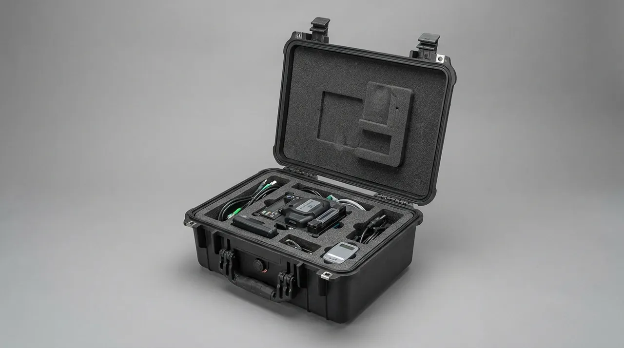
Cushioning and support methods for long thin plate match other precision long items, and contact area and hardness gradient values are set out in cushion liner and support structure design.
Tooth Flank Protection for Circle and Gear Ring
The circle carries the moldboard and lets it rotate about a vertical axis to set different cutting angles. It usually comprises upper and lower rings, connecting webs and an external gear ring that meshes with the circle drive pinion.
The first principle of tooth flank protection is that teeth must never carry weight. Tooth contact stress is calculated for meshing transmission and its load capacity is far below that of structural faces. If a case supports the circle through its teeth, the flanks deform plastically, and after installation the result is periodic shock and noise during rotation, with accelerated wear around the full ring in severe cases.
The correct support method is to carry load on the upper and lower ring faces or the connecting webs. Two arrangements work. The first is horizontal placement with the ring face level, carried in an annular recess covering at least one third of the ring wall thickness. The second is vertical placement with the ring on edge, gripped by two curved saddles from inside and outside, contacting the face rather than the teeth. Horizontal placement is more stable; vertical placement saves case height. The choice depends on case dimensions.
The gear ring should travel either fully meshed with the pinion or fully disengaged. A partially engaged state puts all contact load on a few teeth and is the least favourable condition. Where separation is required, tooth surfaces should take rust preventive grease and a soft protective strip so that nothing hard can touch them.
On machines using a ball-race slewing ring rather than a gear ring, the inner and outer rings must not rotate relative to each other in transit. Temporary locking pins or blocks should be fitted, shipped with the part and tagged. The purpose matches transmission locking: suppressing micro-movement to protect raceways and seals.
Radial runout and face runout of the circle are key machine accuracy indicators. Packing should use three or four evenly distributed supports to avoid ovalisation from one-sided overhang. Re-measurement before packing and after unpacking is worth doing to compare runout change. Transport protection for toothed and bearing mating components follows similar logic, described in gear and bearing housing component protection, covering tooth flank protection and locking methods.
Locking the Circle Drive Box and Worm Gearing
The circle drive box normally combines a hydraulic motor with worm gearing, mounted above the pinion that drives the circle. It is a sealed precision assembly containing worm, worm wheel, bearings and seals.
Locking is the central protection action for this component. A hydraulic motor with no circuit pressure can be back-driven by external force, which means case vibration causes small reciprocating rotation of the output shaft, which in turn micro-moves the worm and wheel. The movement is too small to be visible, but it makes the worm and wheel contact zone rub repeatedly with no oil film, producing early wear. An external locking device must therefore be fitted before dispatch, commonly a plate between motor output shaft and housing, or a locating sleeve on the worm shaft end.
Locking device strength should target 30 to 50 percent of output torque capacity, since the reverse torque in transit comes from inertia rather than working load. Its magnitude is small but its cycle count is very high, so material needs enough toughness to avoid fatigue fracture.
Ports and breathers follow the same rules as other hydraulic components: threaded plug plus dust cap as dual plugging, with the breather removed, bagged and shipped with the part. The oil level check port should also be plugged so that oil cannot escape and contaminate the liner during transit.
On circle drive boxes with a brake, the transport state should be brake-released or locked as the manufacturer specifies. A box travelling partially braked keeps the friction plates under continuous pressure, which over a long journey can cause adhesion or drag. The packing documentation should state the brake state and the on-site release procedure.
The relationship between locking devices and gearbox assemblies matches hoisting machinery, and the treatment of output shaft locking and torque release in hoist and lifting mechanism component protection is directly relevant.
Straightness Retention for Slide Rails and Shift Cylinders
The slide rail is the guiding mechanism that lets the moldboard shift sideways relative to the circle, comprising rail, slider and shift cylinder. Its function is straight guidance, so guide face straightness and parallelism are the core indicators.
Three failure modes apply in transit: bending, guide face damage and slider separation. Bending comes from insufficient support, guide face damage from hard contact, and slider separation from missing limiting. Consequences differ: bending raises shift resistance and causes position drift, guide face damage causes local binding, and slider separation can scatter and lose balls or rollers.
Straightness retention is achieved by evenly spaced multiple supports with guide faces oriented away from contact. Slide rail section stiffness is much lower than that of a moldboard, so support spacing must be denser. As a rule, spacing should hold self-weight deflection to around one ten-thousandth of length, with the exact value derived from section moment of inertia and support arrangement.
Guide faces should face the case interior without contacting other items. Where contact with liner material is unavoidable, liner hardness must be lower than the guide face and contact pressure must stay below the allowable value. A common practice is a protective film or strip over the guide face, with the strip itself not in hard contact with the case wall.
The shift cylinder usually ships assembled to the rail. Two cautions apply. First, the rod should be retracted so no exposed section carries load. Second, cylinder thrust must never serve as the transport restraint. Internal pilot-operated check valves or counterbalance valves provide no locking capability without pressure, so any arrangement relying on them will allow the rail to creep during transit.
Rail bores and mounting pads need individual protection: process plugs for bores, protective film plus rust preventive grease on mounting faces. Methods for this class of slender guided component are described in linear actuator and slide rail transport protection, covering guide face protection and multi-point support.
Clearance Management for Tilt Linkage and Rods
The moldboard tilt linkage rotates the moldboard about its longitudinal axis to set crossfall. It comprises tilt cylinder, rods, pins and spherical joints. Unlike a bulldozer push arm, the tilt linkage is precision guided, and clearance at each joint directly affects moldboard crossfall repeatability.
Clearance management means preventing new clearance from developing in transit. New clearance arises from pin bore deformation through impact, or from forced displacement of spherical joints and bushings under vibration. Prevention is identical for both: joints must carry zero or near-zero load in the transport condition.
Three methods apply, chosen by circumstance. The first is separated shipment: cylinder, rods and pins packed independently, all bores process-plugged, spherical joints sleeved. This is safest and suits customers with assembly capability on site. The second is assembled with rigid locking: assembly relationships are preserved but a rigid stop locks the mechanism at the design position and circuit pressure is released. The third is assembled with offloading: assembly relationships are preserved but external supports route the mechanism's weight and inertia into the case so the joints carry no load. All three must be documented, stating the transport condition and the on-site steps.
With assembled shipment, the tilt cylinder rod is often partly extended and must be sleeved over its full exposed length. Nitrile rubber or expanded polyethylene works; bubble film must not be used.
Spherical joint seals are a vulnerable point. A seal damaged in transit lets grit into the spherical clearance and accelerates wear, showing up after installation as excessive clearance and noise. Spherical joints should be sleeved with the seal confirmed intact before packing. Clearance control for linkage and frame connections is covered in chassis frame and bracket structural component protection, including bore and mating face protection.
Case Size Boundaries and Split Packing Strategy
Grader component lengths vary enormously, from a 0.3 m circle drive box to a 4.3 m heavy duty moldboard, an order of magnitude apart. One packaging system cannot cover all types sensibly, so split packing boundaries must be explicit.
A 2 m boundary works well. Components shorter than 2 m, such as circle drive boxes, shift cylinders, tilt cylinders, sensor assemblies, pins and spares, go into standard protective cases with load class graded by mass. Components longer than 2 m, such as moldboards, slide rails, long rods and front moldboards, go onto long cradles. Cradles can be combined with standard cases as a system: long items on cradles, short items in cases, bound together by a unified packing unit number.
The boundary is set by structural efficiency rather than cost. Beyond 2 m, the lateral stiffness of a standard case wall falls relative to length, torsional performance degrades and handling and stacking become difficult, whereas a long cradle is structurally efficient along its length and light in tare weight. The dividing line is therefore about structural soundness.
An alternative strategy is sectional packing. Where a slide rail or rod can be split, packing it as two shorter items significantly reduces difficulty. That strategy requires confirming that accuracy recovers after reassembly and that the disassembly and reassembly process introduces no new deformation. Where the customer lacks on-site calibration capability, sectional packing is not advisable.
Reusability also affects the boundary choice. Returnable cases need liner condition and hardware life checks after repeated use, and long cradles generally outlast cases because their structure is simple and they contain no seals. Life management and inspection intervals for returnable packaging are described in protective case service life and inspection intervals.
Case hardware selection, meaning latches, hinges and handles, must match case size. Long cases need more latches along the edge so that gasket compression does not become uneven over a long unsupported span. The selection logic is described in case latch customisation and selection.
Liner Design for Long Precision Items
Liner design for long precision items differs fundamentally from block-shaped items. Where a block liner mainly solves restraint, a long item liner must solve support and restraint together, with support taking priority.
Support means the liner must be continuous or evenly segmented along the length rather than fixed only at the ends. End-only fixing leaves the middle free, and the long item deflects under self-weight and vibration. Long item liners therefore typically combine saddle strips with end pockets: evenly spaced saddle strips along the length, plus shape-matched end blocks limiting axial displacement.
Saddle strip profile must match the item outline. For a curved moldboard back, the strip upper surface should be a concave arc of the same radius. For a flat slide rail base, it should be flat with radiused edges. Strip width should not be too narrow; a working minimum is 20 percent of item width to avoid line contact.
End pocket depth involves a trade-off. Too shallow and axial displacement is not limited; too deep and loading becomes difficult with a risk of scratching on entry. A practical range is 30 to 50 percent of end height or width, with finger slots at the base.
Long items have one further axial requirement: a small amount of thermal expansion must be permitted. Metal components can see a 40 degree Celsius swing in transit, and a 3 m steel item changes length in the millimetre range. If both ends are rigidly limited, thermal expansion generates axial compressive stress inside the item which, added to other loads, can cause instability. The recommended arrangement is a rigid limit at one end and a resilient limit at the other.
On material selection, long items present large contact areas, making them more sensitive to compression set. At the same compression rate, a large contact area generates greater total compressive force and the material creeps more readily. Liners for long items should therefore use material with lower compression set, with compression rate taken slightly lower. Pocket layout for long items is described in vibration damping and cushion liner structures, covering damping travel and limiting.
Support Spacing Calculation for Deformation Control
Support spacing must be calculated from beam deflection rather than estimated. For a simply supported beam under uniformly distributed self-weight, maximum deflection occurs at mid-span:
d = 5 q L^4 / (384 E I)
Here q is load per unit length in N/mm, L is support spacing in mm, E is elastic modulus in N/mm2 and I is section moment of inertia in mm4. For steel, E is taken as 2.06 x 10^5 N/mm2.
The practical value of this expression is that deflection varies with the fourth power of support spacing. Halving the spacing reduces deflection to roughly one sixteenth. When calculated deflection exceeds the allowable value, adding support points is therefore far more effective than thickening the component.
| Support arrangement | Points | Spacing to length ratio | Relative deflection | Recommended use |
|---|---|---|---|---|
| --- | --- | --- | --- | --- |
| Simply supported ends | 2 | L equals full length | 1 (baseline) | Not recommended for precision long items |
| Three evenly spaced | 3 | L about half length | About 1/16 | Medium precision items under 1.5 m |
| Four evenly spaced | 4 | L about one third length | About 1/81 | Common starting point for moldboards and rails |
| Five evenly spaced | 5 | L about one quarter length | About 1/256 | Long moldboards and heavy long items |
| Continuous support | Full-length saddle | Approaches zero | Negligible | Highest precision or very long items |
Allowable deflection should be set from functional requirements. For moldboards, one thousandth to two thousandth of length is reasonable. For slide rails, where guidance accuracy is tighter, one two-thousandth to one five-thousandth is appropriate. It should be noted that this deflection is elastic and recovers on unloading. What causes real functional loss is plastic deformation beyond the elastic limit combined with accumulated creep, so the calculation should also confirm that surface stress stays within a sensible fraction of yield strength, typically no more than 30 percent.
Stacking load must be added to self-weight. Where the case will be stacked, the load on a moldboard rises significantly and support spacing must be recalculated using stack layers multiplied by equivalent single-layer load. Stacked conditions are best modelled as a continuous beam on multiple elastic supports, or more conservatively checked as a simply supported beam at maximum span.
Once calculated, support positions must be integrated with case structure. Each support point needs reinforcement or a load plate beneath it, otherwise load passes through the liner into a flat case floor and deflects it. Pocket layout methods and values are described in custom foam insert pocket design.

Rust Prevention and Hydraulic Cleanliness Control
Grader component rust prevention works at two levels: component level and case level.
Component level protection is graded by face type. Guide faces, pin bores, spherical joint mating faces and mounting faces are precision machined and should take soft-film rust preventive oil or grease at 20 to 40 micrometres, applied after confirming the surface is dry and clean. Gear ring tooth surfaces should take rust preventive grease with a soft protective strip over them. Non-machined structural faces can take a fast-drying preventive agent for easy removal on site.
Case level protection covers sealing, drying and breathing. For long ocean voyages, IP67 on the primary gasket is advisable, verified to IEC 60529 or GB/T 4208, with desiccant and a humidity indicator card inside. A breather valve balances differential pressure so that the gasket is not pushed out of its groove and humid air is not drawn in.
Cleaning before packing deserves emphasis. Grader components contact cutting fluid, cleaning agents and handling perspiration during manufacturing and trial assembly, and these residues markedly reduce the adhesion of rust preventive coatings. Cleaning sequence and dryness confirmation methods are described in protective case and component cleaning procedure.
Hydraulic cleanliness is managed on the ISO 4406 scale. Preservation cleanliness for circle drive boxes, shift cylinders and tilt cylinders should be at least 19/17/14. Where they ship in the same batch as a main control valve or proportional valve, the valve should be at least 18/16/13. All ports and inspection ports must be double-plugged, with a plug list inside the case and tags stating removal before installation.
For corrosion verification the applicable method sits inside GB/T 10125, the artificial atmosphere corrosion test standard. Exposure length is chosen from the destination climate. Inland routes can be cleared at 48 hours with no red rust present. Sea freight warrants 240 hours. Coastal storage over a long horizon calls for 480 hours. These hour counts serve comparison between candidate designs, or as a baseline agreed in contract; they should never be read as a direct predictor of years in the field.
On compatibility between rust preventive oil and liner material: some foams absorb the oil, thinning the film or drying it locally. A barrier film between oiled surface and liner, or a closed-cell liner with low oil absorption, resolves this.
Test Verification and Dispatch Records
Acceptance testing should cover three lines: structure, environment and sealing. Criteria on all three must be measurable.
The structural line covers static bearing observation and dynamic vibration. Static bearing applies stacking load plus one layer of margin for at least 24 hours, after which liner bearing point depressions are checked against 10 percent of original thickness with a recovery requirement. Dynamic vibration follows the GB/T 4857 series of basic tests for transport packages, after which contents displacement (under 2 mm), liner impressions, fastener loosening and divider deformation are inspected.
The environmental line covers salt spray and damp heat. Salt spray follows the salt spray portion of GB/T 10125, with criteria of no red rust on metal parts and no blistering or flaking of coatings. Where MIL-STD-810H methods are cited, the citation must state that the standard serves only as the source of environmental test methods and conditions for verifying behaviour in those environments, and that it is not a military certification.
The sealing line covers IP immersion and whole-case airtightness. IP67 follows IEC 60529 or GB/T 4208, with 30 minutes at 1 m depth followed by internal inspection. Whole-case airtightness determines sealing system continuity by measuring pressure decay after pressurising or evacuating, and suits full pre-shipment inspection.
| Test category | Reference | Condition highlights | Acceptance criterion |
|---|---|---|---|
| --- | --- | --- | --- |
| Static bearing | Works specification or contract | Stacking load plus one layer, at least 24 h | Liner depression under 10 percent of thickness, recoverable |
| Random vibration | GB/T 4857 series | Spectrum by transport mode, in stacked state | Displacement under 2 mm, no through impressions |
| Drop | GB/T 4857 series | Drop height by unit mass and transport mode | No component damage, no case rupture |
| Salt spray | GB/T 10125 | Neutral salt spray 50 g/L plus or minus 5 g/L at 35 plus or minus 2 C | No red rust at 48 h or 240 h by environment |
| Sealing | IEC 60529 or GB/T 4208 | IP67: 1 m depth for 30 minutes | No water ingress |
| Airtightness | Works specification or contract | Pressure or vacuum decay measurement | Decay within limit |
Dispatch records should be traceable, covering case number, liner drawing number and revision, contents list, support point layout, locking device and plug lists, test report number, and packer and verifier. For precision items it is worth adding a post-packing re-measurement record capturing key datum values, so that pre-transit and post-transit comparison is possible. Full acceptance and sampling flow is described in protective case service life and inspection intervals, covering recheck intervals and rejection criteria.
Frequently Asked Questions
Q: A grader moldboard is only about 3 metres long. Are four support points enough?
A: Sufficiency must be confirmed by deflection calculation, not judged from length. For a simply supported beam under uniformly distributed self-weight, maximum deflection varies with the fourth power of support spacing, so halving spacing cuts deflection to roughly one sixteenth. Four evenly spaced points place spacing at about one third of total length, reducing deflection to roughly one eighty-first of the two-end baseline, which is a sound starting point for most standard moldboards. Whether it meets the allowable value still depends on actual parameters: plate thickness, curved section moment of inertia, mass per unit length and allowable deflection. Allowable deflection is typically set at one thousandth to two thousandth of length. If the calculation leaves insufficient margin, adding one support point is far more effective than thickening the moldboard. Stacking must also be considered: where the case will be stacked, recalculate using equivalent load derived from stack layers. Support points must also align with reinforcement ribs on the moldboard back, because a support between two ribs creates local bearing on the face plate and leaves an impression even when total deflection passes.
Q: Why can the circle not be supported on its teeth when the teeth look substantial?
A: Toothed surfaces and structural faces are fundamentally different in design intent. Structural faces such as ring ends and webs are designed to carry pressure and bending, with large contact areas and even stress distribution. Teeth are designed to transmit meshing torque, with line contact and contact stress controlled by tooth profile curvature. So although permissible contact stress on a tooth flank is numerically high, the contact region is extremely small, and any concentrated pressure produces local stress beyond the elastic limit, creating plastic deformation. After installation, that deformation appears as periodic shock and noise during rotation, because the deformed tooth interferes with its mating tooth. Worse, gear accuracy is defined by pitch deviation and profile deviation, and local plastic deformation damages both at once and cannot be corrected in the field, so the entire ring eventually needs replacement. The circle should therefore be carried on end faces or webs, with teeth either fully meshed or fully disengaged and protected, and never left in a partially engaged state.
Q: Why does a circle drive hydraulic motor need an external locking device?
A: Because a hydraulic motor with no circuit pressure can be back-driven by external force, which runs against intuition but follows from the structure. With no pressure at the return port there is no back-pressure restraint, so case vibration passes through the mounting into the motor housing and then through gear meshing into the output shaft, producing small reciprocating rotation. The displacement is small, usually invisible to the eye, but it makes the worm and wheel rub repeatedly over the same contact zone with almost no oil film. Worm gearing is dominated by sliding friction and is highly sensitive to lubrication state, so once the film breaks down wear accelerates quickly, and wear debris stays in the sealed cavity as further abrasive. An external locking device must therefore be fitted before dispatch, rigidly connecting output shaft to housing. Locking device strength should target 30 to 50 percent of output torque capacity, because the load comes from inertia rather than working load. Magnitude is small but cycle count is very high, so material needs enough toughness to avoid fatigue fracture.
Q: Why must slide rail support spacing be denser than for the moldboard?
A: Because the slide rail section stiffness is clearly lower than the moldboard's, and its accuracy requirement is higher. The moldboard, though long, is a large-radius curve combined with reinforcement ribs, giving a relatively large section moment of inertia. A slide rail is typically a rectangular or profiled guide section with less material concentration, so its moment of inertia at the same length is much smaller. Deflection is inversely proportional to section moment of inertia, so at equal load and spacing the rail deflects noticeably more. At the same time, the rail provides straight guidance, and guide face straightness translates directly into position deviation during lateral shift, which then affects longitudinal surface evenness. Its allowable deflection is therefore tighter, typically one two-thousandth to one five-thousandth of length. The two factors combine to demand denser spacing, usually five to seven evenly spaced points. Guide faces must also face away from contact; where contact with liner is unavoidable, contact pressure must remain below the allowable value with a protective strip over the guide face. The rail usually ships assembled to a cylinder, and the cylinder must never be used as the transport restraint.
Q: For tilt linkage pins and spherical joints, is assembled or separated shipment better?
A: The difference lies in the load state at the joints. With separated shipment, cylinder, rods and pins are packed independently and the joints carry no load at all, which is safest, at the cost of requiring assembly capability and torque tooling on site. Assembled shipment requires one of two measures: a rigid stop locking the mechanism at the design position, or external supports offloading the mechanism's weight and inertia into the case. Without either, the tilt linkage weight passes through pins and spherical joints into the case, and case vibration applies alternating load at the joints, producing irreversible clearance growth in bores and spherical mating faces. The grader tilt linkage is precision guided, and clearance directly affects crossfall repeatability, which is very hard to compensate once out of tolerance. The preferred order is therefore separated shipment first, assembled with rigid locking second where site conditions prevent separation. If assembled shipment is used, the packing documentation must state the transport condition, locking device location and removal sequence, and the locking devices must ship with the part.
Q: Does moldboard curvature really change in transit, and how is it verified?
A: It does change, and the criterion is recovery after resting rather than visual inspection. The moldboard is a large-radius curved structure with evenly distributed self-weight, and with insufficient support it behaves as a deflecting beam. Short-term deflection is elastic and recovers on unloading, but sustained static load combined with stacking load converts part of it into permanent deformation, appearing as curvature deviation. Verification is best done in three steps. First, measure the moldboard back curvature with a template or coordinate measuring machine before packing and record the datum. Second, after packing, measure the height difference between the two moldboard ends relative to the case floor as the pre-transit record. Third, rest for 24 hours and re-measure; the difference between the two values should be under one third of the allowable straightness deviation, confirming support layout and contact condition. After unpacking, measure curvature again and compare with the pre-packing datum; the change should fall within allowance. The value of these records is not only in detecting problems but in clarifying responsibility, since an out-of-tolerance result after unpacking can be attributed to packing layout or to external impact on the evidence.
Q: Do long items need rigid limits at both ends?
A: Rigid limits at both ends are not advisable, because of thermal expansion. Metal components can see a 40 degree Celsius swing in transit, and a 3 m steel item changes length in the millimetre range. That sounds small, but with both ends rigidly constrained, the expansion can only be absorbed by elastic or plastic deformation of the item itself, which is equivalent to applying axial compressive stress internally. That stress alone is usually insufficient to buckle a long item, but it stacks on transport vibration and environmental loads, reducing safety margin and potentially causing local instability at ends or section transitions. A more sensible arrangement is a rigid limit at one end and a resilient limit at the other. The rigid end carries primary axial load such as braking or impact, while the resilient end uses compressible liner at 25 to 35 percent compression, maintaining contact while absorbing thermal movement. The resilient end liner needs periodic compression set checks, because large-area contact liners creep more readily under sustained pressure. Where item geometry prevents differentiated limits, resilient limits should be used at both ends with hold-down strips added.
Q: Nothing looks wrong after packing a precision item, so does that prove the packing works?
A: It does not, because precision items mostly fail through invisible elastic or plastic deformation, and visual inspection at packing only reveals obvious damage such as impact marks and displacement. Effective judgement requires quantified records. Three records help. First, measure key datums before packing, such as moldboard curvature, rail straightness and gear ring face runout, and record the datum values. Second, record the height difference between item ends relative to the case floor after packing, and re-measure after 24 hours to confirm that the support layout is not causing continuing settlement. Third, measure key datums again after unpacking and compare with the pre-packing datum; the change should fall within allowance. Together these three records convert invisible deformation into comparable numbers. It is also worth recording the worst conditions on the route, such as whether the case is stacked and how many transhipments occur, so that an out-of-tolerance result can be attributed correctly. Where the customer cannot measure on site, third-party measurement at the packing and unpacking points is a relatively low-cost option that provides objective evidence in a claim.
Conclusion and Related Reading
The design thread through a motor grader parts case is precision rather than strength. Moldboard support points are set by deflection calculation with saddles matching curvature. Cutting edges and end bits are wrapped and counted by segment. The circle carries load on end faces or webs while teeth stay meshed or fully disengaged. The circle drive box receives an external locking device. Slide rails get denser support spacing to hold straightness. The tilt linkage ships separated or rigidly locked. Long items take a rigid limit at one end and a resilient limit at the other. Liners run continuously or in evenly spaced segments along the length. And packing and unpacking re-measurement records turn deformation risk into data. JUNZHIJIA, manufactured by Kexin New Materials (Guangdong) Co., Ltd., supplies combined long cradle and standard case solutions for motor graders and other road and earthmoving equipment, covering custom liner design and case moulding, with global supply for wholesale, agency, OEM and ODM customers, and material certificates and test documents available under contract. For selection support, provide item length, plate thickness or section parameters, individual mass and centre of gravity, and the functional datum face list to receive support point layout and liner drawings directly.
Related Reading