

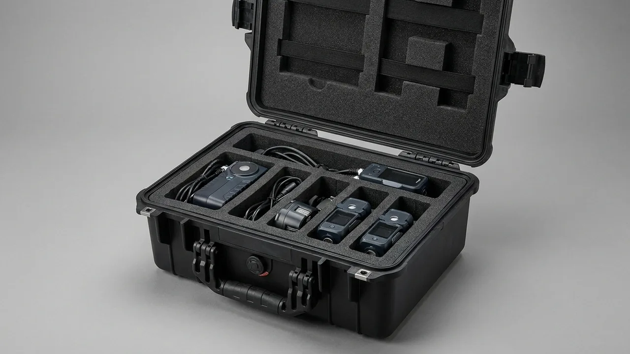
Suspension components fail on a different logic from ordinary structural parts. A damper is ruined when its chrome-plated piston rod is scored and the seal lip then wears through; a spring is ruined when it sits under compression long enough for its free length to decay. Both are latent defects — nothing looks wrong when the case is opened, and the problem only surfaces after the vehicle is assembled and driven. The design priority for a suspension parts case is therefore not thicker cushioning but protecting running surfaces, constraining the posture of energy-storing elements, and shielding seals and rubber from a corrosive atmosphere. A rod with a visible score will wear a seal lip through within a few hundred kilometres, and a coil spring stored compressed can lose enough free length to fall outside its tolerance band.
This article treats dampers, coil springs, leaf springs, anti-roll bars and air springs separately, giving concrete methods for rod sleeves, stroke restraint, upright spring storage and rubber isolation, plus liner material comparisons, test and acceptance procedures, and packing practice. The tables are written to drop straight into a technical annex or an inspection checklist.
Contents
- 1. Why Suspension Components Fail Differently from Structural Parts
- 2. The Four Damage Modes That Threaten Dampers in Transit
- 3. Piston Rod Protection: Chrome Layer, Surface Finish and Sleeve Design
- 4. Oil Seals and Sealing Faces: Why Inversion, Tilt and Heat Cause Weeping
- 5. Coil Spring Free-Length Loss and Load Loss Control
- 6. Standing, Strapping and Cavity Cushioning for Springs
- 7. Leaf Springs, Anti-Roll Bars and Other Long Suspension Members
- 8. Air Springs and Rubber Elastic Elements
- 9. Liner and Sleeve Materials: Clean, Low-Migration, Non-Absorbent
- 10. Rust Control Priorities Under Humidity and Salt Spray
- 11. Sealing, Cushioning Travel and Temperature Range
- 12. Test Basis and Acceptance for Leakage and Relaxation
- 13. Packing and Unpacking Practice
- 14. Case and Liner Selection Reference
- Frequently Asked Questions (FAQ)
- Conclusion and Related Reading
1. Why Suspension Components Fail Differently from Structural Parts
A chassis rail fails visibly — a bend or a rust bloom that can be judged the moment the case is opened. Suspension parts do not behave that way. They are built from running pairs, sealed cavities and elastic energy stores, and their failure is delayed.
A damper is a closed hydraulic chamber with a piston rod sliding through an oil seal. Surface damage to that rod never shows up immediately as a leak. It first produces uneven wear on the seal lip, and by the time weeping becomes visible the damping curve has long since drifted away from its design value. A spring carries the vehicle mass, and its free length and rate are tightly screened at the factory — but long storage under compression lets it stress-relax and slowly shorten.
Three design priorities follow from this. First, preserve the surface integrity of every running pair — the chrome layer on the rod, the band where the seal lip rides, and the dust boot. Second, constrain the posture and loading state of energy stores — springs must not sit compressed, and long members must not carry a bending moment. Third, isolate corrosive media — rubber must be kept away from ozone and grease, and chrome and zinc surfaces must have white rust suppressed.
Those priorities are why a suspension case must be accepted on leakage inspection and free-length re-measurement, not merely on appearance and dimensions.
2. The Four Damage Modes That Threaten Dampers in Transit
Score marks on the piston rod. The rod is precision-ground and hard-chrome plated, with surface finish typically in the Ra 0.2 to 0.4 μm band and a coating microhardness reaching HV 800 and above. That layer resists abrasion well, but once a hard particle cuts a groove, the seal lip follows the groove and creates a leak path. The culprit is rarely a major impact — it is swarf and grit left inside the case.
Bending of the piston rod. With the damper extended, the rod becomes a slender cantilever. Lateral pressure produces micro-bending, and even a few hundredths of a millimetre destroys concentricity between rod and seal, causing one-sided wear and eventual weeping.
Contamination and dry running at the seal lip. The lip is an extremely thin rubber edge held closed by a garter spring. Dust adhering to it embeds in the rubber during reciprocation and ploughs a furrow; prolonged absence of oil causes it to dry and harden.
Oil migration under inversion combined with heat. Oil and pressurised gas are separated by the seal and guide. As case temperature rises, gas pressure climbs. If the damper lies inverted or heavily tilted for a long period, oil pools against the seal and the combined differential makes migration far more likely.
Two of these modes are mechanical and two are environmental, which is why a suspension case has to solve restraint and posture at the same time.
3. Piston Rod Protection: Chrome Layer, Surface Finish and Sleeve Design
Rod protection is the most detail-sensitive part of the whole exercise, and the method is to minimise both contact and exposure at once.
Three sleeve options. A full-length sleeve in PE or PP covers the entire rod with soft end plugs locating it. A partial sleeve covers only the exposed section, which suits short-stroke dampers. An integrated sleeve and stroke limiter protects the rod while holding compression at mid-travel.
Clearance inside the sleeve. The sleeve bore should be 1.5 to 3 mm larger than the rod diameter so it never touches the rod. Contact would turn the sleeve itself into an abrasive carrier. Both sleeve ends must be deburred and radiused where they meet the rod.
Protecting the plating. The quality of engineering chromium plating can be assessed against the requirements of GB/T 11379, with attention to thickness uniformity and adhesion. Two practices must be avoided in transit. Never wrap the rod in coarse recycled paper or wood wool, whose fibres carry hard grit straight onto the surface. Never secure the rod with ordinary adhesive tape, because removing it leaves residue that needs solvent — and solvent attacks the rubber dust boot.
Dust boots and bump stops. A boot is a thin corrugated wall that collapses if crushed. Load it in its natural extended state, or folded exactly as designed, and never place weight on top of it. Bump stops are polyurethane or rubber and must not share a cavity with grease or solvent.
Cleanliness before loading. Wipe the rod clean and apply a thin preservative oil layer. Where cleanliness is poor, particles settle in the sleeve clearance and roll back and forth under vibration.
4. Oil Seals and Sealing Faces: Why Inversion, Tilt and Heat Cause Weeping
Seal weeping is the most common warranty dispute on suspension shipments, and understanding its cause is what makes restraint design effective.
How the seal lip loads. The lip presses radially against the rod through a garter spring. In normal service a very thin oil film forms inside the lip, lubricating and sealing simultaneously. If the rod tilts or runs off-centre, radial pressure becomes uneven — pinched on one side, open on the other.
Temperature against internal pressure. The gas chamber is charged with high-pressure nitrogen, and internal pressure rises with temperature. Container interiors can exceed 60 degrees Celsius in summer, well above the pressure at ambient. If the damper lies inverted at the same time, oil accumulates on the seal side and the differentials add up.
Practical posture restraint. Vertical with the rod upward is preferred. Where case height will not allow it, a tilt of no more than 30 degrees from vertical is acceptable provided the seal side stays above the oil level. Never stack the case inverted, and label the exterior with orientation and stacking warnings.
Long-stroke versus short-stroke. A long-stroke damper fully extended exposes a great deal of rod and carries a higher bending risk. Fixing compression near mid-travel roughly halves the exposed length while keeping the seal lip wetted.
Applying the general sealing logic. The gasket and pressure equalisation architecture of the case strongly affects both internal humidity and thermal buffering, and it follows the same selection logic set out in the case sealing and cushioning structure note.
5. Coil Spring Free-Length Loss and Load Loss Control
A coil spring is a store of elastic energy characterised by free length and rate, and both are sensitive to how it is stored.
The mechanism of free-length loss. A spring held compressed for a long period stress-relaxes, shortening its free length. The loss scales with compression, storage duration and temperature. Store a spring compressed to working height for several months and the loss can push it outside the free-length tolerance band.
So store springs near free length. Load springs close to their free state and size the case height from free length plus cushion allowance. Where case dimensions force compression, keep it within 20 percent of the coil gap and shorten the storage period.
Coating and surface treatment. Springs are normally shot-peened then cathodic e-coated or powder coated, and the residual compressive stress from peening is what sets fatigue life. Impact in transit dents the coil surface and creates a fatigue initiation site. Springs must therefore be separated and never loose-packed.
Leaf spring interleaf treatment. A leaf spring is a stack of leaves with lubricant or anti-friction pads between them. Relative movement in transit wears the coating and changes clamp load. Fix the leaves at their as-built position with clamps or banding, and restrain axial travel with end supports.
Standards to reference. Technical conditions for cylindrical helical compression springs are covered by GB/T 1239.2 for cold-coiled and GB/T 23934 for hot-coiled types, focusing on free-length tolerance, perpendicularity and end-coil flatness. Acceptance can sample and re-measure free length against the factory value.
6. Standing, Strapping and Cavity Cushioning for Springs
Posture decides whether a spring rolls, tilts or collides with its neighbours.
Upright beats lying down. Standing, the spring axis is perpendicular to the support face and coils do not squeeze sideways. Lying down, the spring rolls axially and repeatedly impacts the case wall. If lying down is unavoidable, fit V-shaped cradles at both ends to stop rolling.
Keeping an upright spring upright. A single standing spring tips easily, so machine a circular recess in the liner matched to the outside diameter, at least one third of the diameter deep. Groups of springs can share a compartment with dividers between groups.
When strapping helps. For soft-rate or long-free-length springs, add a single webbing strap around the middle of the coil in addition to recess location, with a soft pad under the webbing to avoid crushing the coating.
Cushion allowance in the cavity. Leave 15 to 25 mm of cushion between the end coil and the case wall, filled with a foam block. Too little and the end coil takes load directly; too much and the spring swings freely.
Grouping and labelling. Springs of different rates look alike, and mixed loading invites the wrong part being pulled. Keep one rate per compartment and label each with rate, free length and batch.
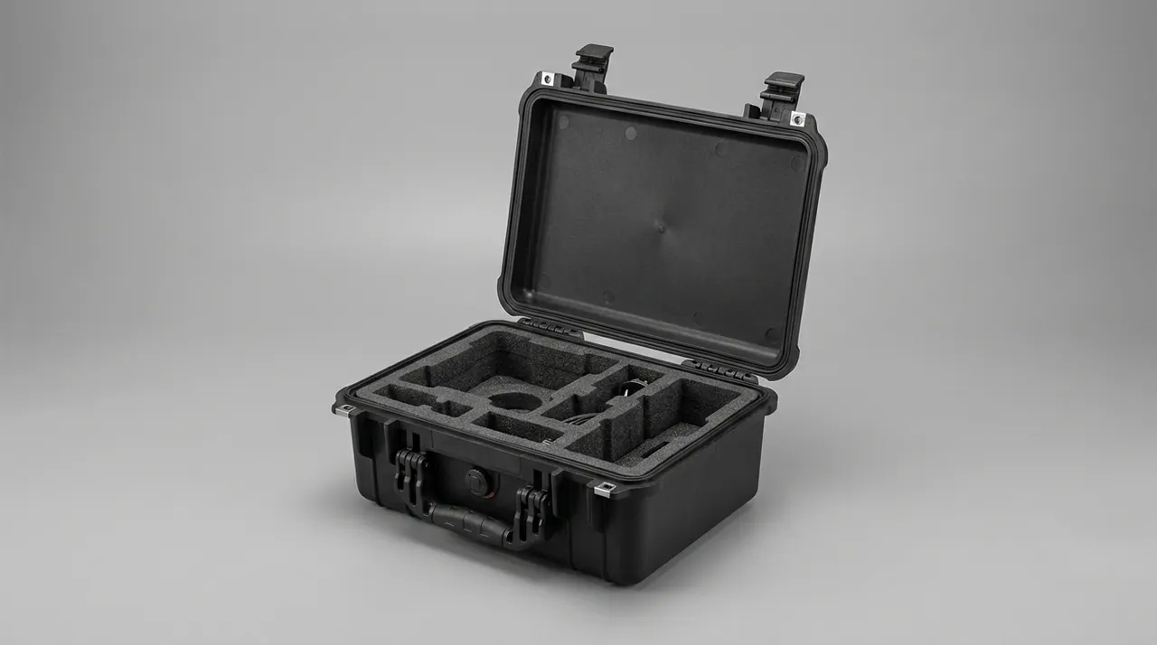
7. Leaf Springs, Anti-Roll Bars and Other Long Suspension Members
Not everything in a suspension system is small. Leaf spring assemblies and anti-roll bars are genuine long members and need different handling.
Leaf spring priorities. A leaf spring is a curved long part, and its camber is a controlling dimension. Reverse bending in transit changes camber and therefore vehicle attitude. Set conforming cradles to the as-built camber so the spring bears on its natural curve, and never support it at a single point on the camber crest.
Eyes and bushings. Leaf spring eyes usually carry rubber or polyurethane bushings, which are precision fits. Fit sleeves into the eyes so they never touch the case wall.
Anti-roll bars. An anti-roll bar is a slender torsion bar with arms at both ends. The torsion section must not be scored, because surface damage sharply reduces torsional fatigue life. The ball studs or bushing bores in the arms need sleeves as well.
Support logic for long members. Like chassis rails, leaf springs and anti-roll bars need multiple supports to hold deflection down, but the criterion differs: camber change governs leaf springs, while straightness of the torsion section governs anti-roll bars, typically one support every 600 to 900 mm.
Strapping and restraint. Use a cradle-plus-strap combination, where the cradle carries vertical load and the strap limits axial travel. Splitting the duties prevents the strap from taking sustained vertical load and relaxing.
8. Air Springs and Rubber Elastic Elements
Rubber fails on an entirely different mechanism, and its protection rules stand alone.
Air spring bellows. The rubber bellows wall is thin and vulnerable to puncture and to being folded to death. Keep the bellows above the minimum design bend radius, never fold it for storage, and never ship sharp-edged fittings such as bolts or clamps in the same cavity.
Ozone and ultraviolet. Rubber cracks under ozone attack, with cracks running perpendicular to the tensile direction. Keep rubber parts out of light and away from ozone sources such as motors and welding equipment. The relevant assessment method is the static tensile ozone cracking test in GB/T 7762.
Keeping grease and solvent away. Rubber stored in the same cavity as mineral oil or solvent swells and loses strength. Where the case also contains metal parts needing preservative oil, use a separate compartment or a barrier film.
Controlling compression set. Rubber under sustained compression takes a permanent set, so load it near its free state and never cinch it with webbing for long periods.
The low-temperature limit. Nitrile rubber stiffens and embrittles markedly when cold, so avoid large deformations during packing and unpacking in cold weather. For routes crossing severe winter regions, verify against MIL-STD-810H Method 502.7, noting that the standard serves purely as an environmental test basis here and does not constitute a military certification.
9. Liner and Sleeve Materials: Clean, Low-Migration, Non-Absorbent
Suspension parts are stricter about liner materials than structural parts, because the contact surfaces are precision finishes or rubber.
| Liner / sleeve material | Typical parameters | Where it fits | Watch-outs |
|---|---|---|---|
| --- | --- | --- | --- |
| Low-hardness EVA closed-cell foam | 25–35 kg/m³ / Shore A 18–28 | Damper pockets, spring recess pads | Coating-friendly; avoid grades with sulphur-bearing additives |
| XPE cross-linked foam | 28–40 kg/m³ / Shore A 25–35 | General dividers, end buffers | Fine skin holds dust; blow clean |
| PE / PP tubing | Bore 1.5–3 mm over rod diameter | Rod sleeves, eye sleeves | No burrs on the bore; radius both ends |
| Moulded PU foam | 45–70 kg/m³ | Contoured cavities, odd-shaped brackets | Higher water uptake; pair with desiccant at sea |
| Non-woven / EPE laminate pad | 2–5 mm thick | Painted-surface isolation | Never use recycled stock; hard inclusions |
| Barrier film (VCI type) | Per GB/T 16267 | Whole-case liner layer | Confirm compatibility with zinc surfaces |
Rule one is to introduce no contaminants. Recycled foam frequently contains metal fragments and grit, and once embedded in the liner skin those particles become a continuous abrasive — fatal to a chrome-plated rod.
Rule two is low migration. Plasticised soft PVC in prolonged contact with rubber or painted parts migrates plasticiser, swelling the rubber and softening the coating.
Rule three is non-absorbency. Closed-cell olefin foams absorb far less water than open-cell types and should be the default for ocean shipments. The differences in compression set and water uptake across foam families can be screened using the measured criteria in the case liner material comparison.
Cleanliness in processing. Blow cut liners with clean compressed air and finish with a tack roller before loading. This step matters more for dampers than for any other product family.
10. Rust Control Priorities Under Humidity and Salt Spray
Suspension parts combine chrome, zinc, painted and bare steel surfaces in one shipment, so corrosion strategy has to be split by surface type.
Chrome-plated parts. Chrome itself resists corrosion well, but once the layer is cut through, the exposed steel forms a small-anode, large-cathode couple and corrosion concentrates at the score and drives inward quickly. The priority is therefore no scoring, not heavy oiling. A thin film of preservative oil wiped evenly with a clean non-woven cloth is sufficient.
Zinc-plated parts. Brackets and clamps plate with zinc show white rust first; white rust is mildly protective but it consumes coating and looks poor if it accumulates. Control humidity and prevent dissimilar-metal contact.
Testing and judgement. Run neutral salt spray to GB/T 10125 or ISO 9227 and rate against GB/T 6461. As a rule of thumb, white rust on zinc within 48 hours is acceptable, while any red rust on a chrome-plated part warrants investigation. For voyages beyond 30 days, add ISO 14993 cyclic corrosion as a supplement.
Moisture control. Size desiccant from free internal volume and barrier film transmission rate, commonly 1 kg of silica gel per 0.5 to 1.0 cubic metres of free volume, taking the upper figure for a 45 day ocean leg. Inhibitor film should meet the requirements of GB/T 16267.
Matching the case seal. Select the seal rating from the actual route and keep it consistent with the corrosion plan, using the classification criteria in the waterproof case IP rating guidance.
11. Sealing, Cushioning Travel and Temperature Range
Sealing and cushioning in a suspension case must resolve a genuine contradiction between keeping moisture out and letting pressure equalise.
Quantified cushioning targets. Take a damper as the example. It is itself a damping element, but that does not make it immune to external shock. A workable target is to keep the acceleration transmitted to the damper body below 40 g in a 1.2 m drop and internal part displacement below 1.5 mm. Cushion thickness is then back-calculated from those two conditions.
Handling the pressure differential. A sealed case develops a differential across temperature swings; under negative pressure the latches fight back and the gasket can be drawn in. A valve that vents air while keeping liquid water out resolves the differential, as described in the case pressure equalisation valve note.
Temperature band. Suspension cases are normally designed for storage and transport between minus 30 and plus 70 degrees Celsius. In the cold the liner stiffens and loses cushioning capacity, while in the heat damper internal pressure rises. Where a route crosses extremes, carry out high-temperature and low-temperature verification under MIL-STD-810H Method 501.7 and Method 502.7. That standard acts here solely as a basis for environmental testing and does not confer military certification.
Combined humidity and temperature effects. Neither cold nor humidity alone is the real threat — the danger is condensation when temperature drops sharply. The thermal inertia of the cushioning material slows the rate of internal temperature change and therefore reduces condensation probability, which is a useful secondary benefit of thicker cushioning.
12. Test Basis and Acceptance for Leakage and Relaxation
Acceptance here must include functional checks, which is what separates suspension packaging from general structural packaging.
| Functional check | Standard used | How it is run | Acceptance rule |
|---|---|---|---|
| --- | --- | --- | --- |
| Transit vibration | GB/T 4857.23 / ISTA 3E / ASTM D4169 | 30 to 60 minutes on each axis, three axes in total | Nothing shifts beyond 1.5 mm and nothing rattles inside the case |
| Impact resistance | GB/T 4857.5 | Corner, three edges and six faces, height set by mass | Casing stays whole and no bend appears in a piston rod |
| Stacked load | GB/T 4857.3 | Three cases high for a full day | Stack does not sink and no spring cavity takes a permanent crush |
| Seal weeping | In-house function test | Leave undisturbed for 24 hours after opening, then look | No oil trace appears around a seal lip |
| Spring length | GB/T 1239.2 / GB/T 23934 | Sample measured against despatch records | Any shortening stays inside the drawing tolerance |
| Corrosion screening | GB/T 10125 / ISO 9227 | 48 to 96 hours of neutral fog | Rating applied per GB/T 6461 |
| Corrosion, cyclic | ISO 14993 | Alternating condensation and drying phases | Coating shows neither bubbles nor lifting |
| Climate cycling | MIL-STD-810H Method 507.6, a test basis only rather than a military certification | Transport profile as agreed | No pooled condensate and no change in gasket hardness |
How to run the leakage check properly. Inspect the seal area and lower housing visually first, then re-check after 24 hours. If oil is present immediately, separate transit weeping from factory residue by looking at the trace boundary — fresh, or dust-adhered.
Checking rod straightness. Measure runout along the full rod length with a dial indicator. As a rule of thumb, total runout within roughly 0.05 mm is acceptable. Anything beyond that should be judged part by part rather than rejected as a lot.
Sampling for free-length re-measurement. Sample at the general inspection level in GB/T 2828.1 and deliberately cover parts from different positions in the case, so any position-dependent compression effect becomes visible.
13. Packing and Unpacking Practice
Sequence on the packing side. Confirm the rod is clean and thinly oiled, fit the sleeve and fix compression at mid-travel, load vertically into the liner pocket, then add desiccant and inhibitor film and close the case. Springs are re-measured and logged before going into the correct rate compartment.
Three prohibited actions. Never handle the piston rod with bare hands, because salt in perspiration becomes a corrosion initiation point. Never store dampers and springs in the same cavity, because the coil profile catches and tears dust boots. Never leave foreign objects on the gasket land.
Labelling. Mark the exterior with orientation, no-inversion, moisture and stack-limit warnings, and label each internal compartment with part number and batch.
Sequence on the unpacking side. Photograph the as-received state first, then remove inhibitor and desiccant, then take parts compartment by compartment. Leave rod sleeves in place until the part reaches the assembly station so the rod is never exposed in transit between stores and line.
Short-term storage. Keep sleeves fitted on parts not going straight to the line, and complete either assembly or re-oiling within 72 hours.
14. Case and Liner Selection Reference
| Component type | Recommended posture | Location method | Liner recommendation | Special requirement |
|---|---|---|---|---|
| --- | --- | --- | --- | --- |
| Damper, stroke ≤ 120 mm | Vertical, rod up | Circular recess plus sleeve | EVA 25–30 kg/m³ | Fix stroke near mid-travel |
| Damper, stroke > 120 mm | Vertical or tilt ≤ 30° | Circular recess plus end cradle | EVA 28–35 kg/m³ | Reduce exposed rod length |
| Coil spring | Upright, standing | Circular recess, depth ≥ 1/3 diameter | EVA 30 kg/m³ | Hold near free length |
| Leaf spring assembly | Flat at as-built camber | Conforming cradle plus end stop | EVA 35 kg/m³ with HDPE base | Never support at camber crest |
| Anti-roll bar | Horizontal | Multi-point cradles at 600–900 mm | EVA 30 kg/m³ | No hard contact on torsion section |
| Air spring | Natural bend within min radius | Contoured cavity, no sharp corners | EVA 25 kg/m³ | Isolate from sharp-edged parts |
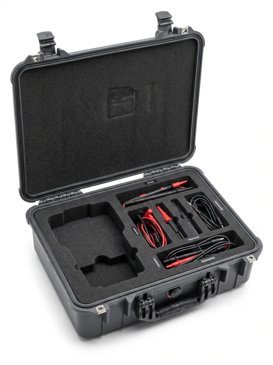
Mixed loading principles. When several suspension part types share a case, group first by whether the part contains rubber or a seal — those go into dedicated cavities. Then group by mass, heavy parts low and light parts high, so heavy items cannot crush light ones under vibration.
An economical route for small batches. For prototypes and low volumes, a case with interchangeable liner modules lets one shell cover several damper sizes. Machining methods and tolerance control for those liners are covered in the EVA insert custom process note.
Manufacturing and supply. Suspension parts cases of this type are manufactured by Kexin New Materials (Guangdong) Co., Ltd. under the JUNZHIJIA brand. Dedicated pocket geometry can be developed for a specific damper size or spring profile, and the business accommodates both build-to-print and joint development from a part model through to the cavity drawing. Sales channels cover volume wholesale, regional agency and direct export supply, and liner material certificates, dimensional reports and salt spray or cyclic corrosion records can accompany the goods within the contracted scope.
Frequently Asked Questions (FAQ)
Q: Which part of a damper most needs protection in transit, and why not the housing?
A: The piston rod, specifically the integrity and straightness of its chrome plating, is the critical item. The housing is normally thick-wall steel tube and tolerates knocks far better than the rod does. The rod is a slender, precision-ground, hard-chrome plated member with surface finish in the Ra 0.2 to 0.4 μm band; the coating is hard but brittle, and once a hard particle cuts a groove the seal lip follows that groove and establishes a leak path. Bending is the more insidious risk. With the damper extended the rod behaves as a cantilever, and lateral pressure produces micro-bending of a few hundredths of a millimetre that no one can see, yet it destroys concentricity between rod and seal, causing one-sided wear and eventual weeping. Three practices follow. Fit a PE or PP sleeve over the full rod length with a bore 1.5 to 3 mm larger than the rod so there is no contact. Fix the compression stroke near mid-travel to shorten the exposed length. And remove every trace of swarf and grit from the case, because those particles are the abrasive that does the scoring.
Q: Why can a damper not be shipped inverted, and how much tilt is acceptable?
A: A damper is a closed chamber in which hydraulic oil and high-pressure nitrogen coexist, separated by the seal and guide assembly. That separation is stable at ambient temperature, but when case temperature rises the gas pressure climbs and the oil becomes more mobile. If the damper lies inverted for a long period, oil pools by gravity against the seal side and the combined internal-external differential makes migration past the lip far more likely. Container interiors exceeding 60 degrees Celsius in summer are routine, which makes inversion combined with heat the highest-risk condition. The engineering response is to stand the damper vertically with the rod upward. Where case height genuinely will not allow that, a tilt of up to 30 degrees from vertical is acceptable, provided the seal side always remains above the oil level. In addition, the case itself must never be stacked inverted, the exterior should carry orientation and no-inversion labels, and the transport agreement should state the required handling and stacking orientation explicitly.
Q: When packing coil springs, should they be compressed or left at free length?
A: Leave them close to free length. A coil spring is an elastic energy store, and stored under compression over a long period it stress-relaxes, meaning its free length gradually shortens. The loss grows with compression amount, storage duration and temperature. Compress a spring to working height for several months and the free-length loss can land outside the tolerance band, which after assembly shows up as low vehicle attitude or an under-rated suspension. Case height should therefore be sized from free length plus cushion allowance rather than from the compressed dimension. Where case dimensions genuinely force compression, hold it within 20 percent of the coil gap and keep the storage period short. At acceptance, sample and re-measure free length against the factory value, applying the free-length tolerance rules in GB/T 1239.2 or GB/T 23934. Note also that spring surfaces are shot-peened and coated, so impacts in transit create dents that become fatigue crack initiation sites, which is why physical separation between springs is mandatory.
Q: How does the rust protection strategy for suspension parts differ from that for chassis frames?
A: The key difference is that suspension shipments combine chrome, zinc, painted and rubber surfaces in one case, so the strategy must be split by surface type rather than applied uniformly. For chrome-plated parts such as piston rods, the priority is not heavy oiling but avoiding scores, because once the layer is cut the exposed steel forms a small-anode, large-cathode couple with the surrounding plating and corrosion drives rapidly inward at the score. A thin, evenly wiped film of preservative oil is sufficient. Zinc-plated brackets and clamps show white rust first, which is mildly protective, but dissimilar-metal contact with bare steel must be prevented. Painted springs need coating integrity and an undamaged peened layer. Rubber is the opposite case entirely and must be kept away from mineral oil and solvent, which swell it and reduce strength. At case level the standard combination still applies: VCI barrier film meeting GB/T 16267, plus desiccant sized from free volume and film transmission rate, commonly 1 kg of silica gel per 0.5 to 1.0 cubic metres of free volume.
Q: What special restrictions apply to packing air springs and other rubber components?
A: Rubber fails on a completely different mechanism, so the restrictions are their own set. First, no folding to death: the air spring bellows wall is thin, storage bend radius must stay above the design minimum, and a folded crease becomes a crack initiation site. Second, no sharing a cavity with sharp-edged parts: bolts, clamps and springs must be isolated from the bellows, because a point contact under vibration is enough to puncture the wall. Third, no exposure to grease or solvent, since mineral oil and organic solvent swell the rubber, reduce hardness and cut strength; where the case also holds oiled metal parts, use a separate compartment or a barrier film. Fourth, avoid ozone and ultraviolet, because ozone attack produces cracks perpendicular to the tensile direction, so keep rubber away from motors and welding equipment and out of light, referencing the static tensile ozone cracking test in GB/T 7762. Fifth, control compression set by storing near the free state and never cinching with webbing for long periods.
Q: Why should recycled foam never be used as a liner, and where is the risk?
A: Recycled foam offers an obvious cost advantage, but in suspension packaging the risk outweighs the saving by a wide margin. During crushing and re-pelletising, recycled stock inevitably retains metal fragments, grit and hard inclusions. Some sit beneath the foam skin and some sit exposed at the surface. Every time a part moves microscopically against the liner under vibration, exposed particles act like sandpaper on the contact surface. On a piston rod that action is enough to cut grooves into the chrome layer. On a painted spring it creates point breaches that rust in humid conditions. On rubber it can produce local cuts that become crack origins. Beyond particles, recycled foam also has inconsistent compression-set behaviour, so rebound differs after prolonged loading and parts in different parts of the case end up under different loads — one reason spring free-length loss sometimes shows a position-dependent pattern. Specify virgin closed-cell foam, blow it clean with compressed air after cutting, and finish with a tack roller before loading.
Q: How do we verify that a suspension parts case design actually works?
A: Appearance alone proves nothing, so functional checks belong in acceptance. Verify in three layers. The first is transport testing: random vibration to GB/T 4857.23, ISTA 3E or ASTM D4169 across three axes, drop to GB/T 4857.5 covering one corner, three edges and six faces, and stacking to GB/T 4857.3 at three tiers for 24 hours, with acceptance criteria of internal displacement no greater than 1.5 mm and total rod runout within roughly 0.05 mm. The second is functional re-measurement: inspect dampers for leakage by viewing the seal area and lower housing, then re-check after 24 hours, and sample springs per GB/T 2828.1 to re-measure free length against factory values, watching for systematic differences by position in the case. The third is environmental testing: 48 to 96 hours neutral salt spray to GB/T 10125 or ISO 9227, cyclic corrosion to ISO 14993, and where required temperature and humidity cycling to MIL-STD-810H Method 507.6, used here purely as an environmental test basis and not as a military certification.
Q: When several suspension part types are mixed in one case, what governs the loading sequence and separation?
A: The governing risks are heavy parts crushing light ones, oily parts contaminating rubber, and sharp edges damaging precision surfaces, so grouping has to consider material compatibility, mass distribution and geometry simultaneously. Step one is grouping by material and medium: parts containing seals or rubber form a sensitive group that must occupy dedicated cavities, isolated from oiled metal parts and sharp fasteners. Step two is grouping by mass: heavy parts go low and near the centre of gravity, light parts above, so inertial forces in vibration act favourably on the light parts instead of letting heavy items hammer them vertically. Step three is grouping by geometry: long members such as leaf springs and anti-roll bars take multi-point cradles, helical parts take circular recesses, and thin corrugated items such as dust boots and bellows keep natural extension space. Step four is consistent labelling, keeping one specification per compartment with rate and batch marked so similar-looking springs or dampers are not swapped. Finally, keep the mixed-load centre of gravity within 50 mm of the case's geometric centre for stable lifting.
Conclusion and Related Reading
A suspension parts case earns its keep by blocking failures that cannot be seen. Zero scoring on the chrome rod, a seal lip that stays wetted and never sees uneven radial pressure, springs stored close to free length, and rubber kept clear of grease and ozone — get those four right and leakage and relaxation disputes drop sharply after unpacking. The supporting actions are to put leakage inspection and free-length re-measurement into the acceptance checklist, to pin the design down with vibration, drop, salt spray and cyclic corrosion testing, and to label orientation and stacking requirements on the outside of the case. Raise the packaging standard for suspension parts and the rework at the assembly line and the early-life warranty failures both fall with it.
Related Reading