

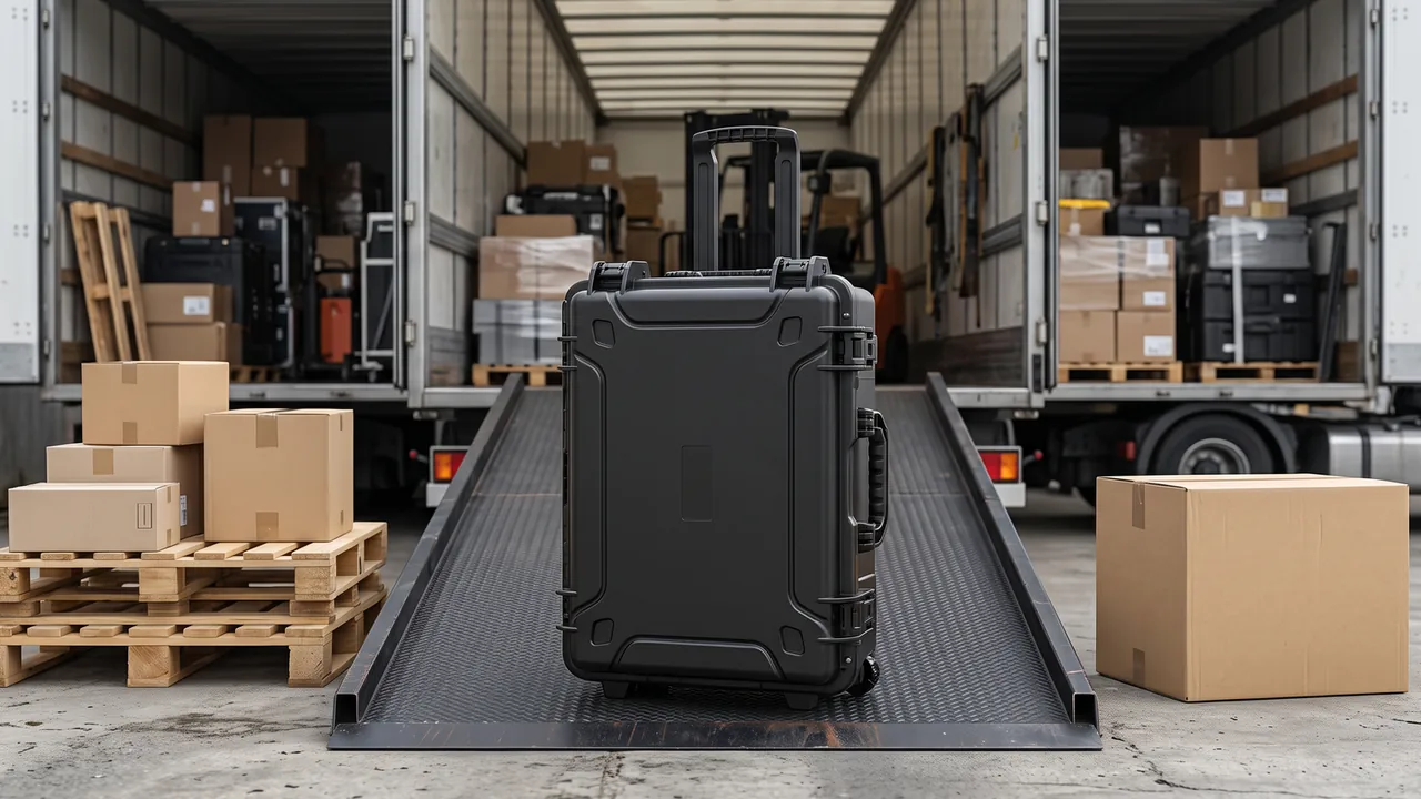
Chassis side rails and mounting brackets are long, torsionally soft, hole-critical structural parts. The real packaging problem is not fitting them inside a box — it is holding self-weight deflection in check, locking the hole datum, and eliminating steel-on-steel contact. A six-metre truck rail supported only at its two ends will sag several millimetres at mid-span under its own weight, and that sag shows up later as a flatness deviation and a misaligned mounting hole. Brackets are worse in a different way: they come in volume, their outlines are irregular, and when they are loose-packed their edges chew through machined faces and e-coat.
The workable approach is a multi-point rigid support path for long rails plus individually compartmentalised pockets for every bracket. Closed-cell foam handles the zoning, volatile corrosion inhibitor and desiccant handle the humidity, and the result is a package that holds distortion and rust in check across a 30 to 45 day ocean voyage. This article walks through the mechanics, the support layout, hole protection, liner hardness matching, the corrosion stack-up, sealing and pressure equalisation, lifting and stacking, and finally the test basis and packing workflow. The tables can be lifted directly into a quotation or a technical annex.
Contents
- 1. Where Frame Rail and Bracket Damage Actually Originates
- 2. Why Chassis Components Need a Purpose-Built Case
- 3. Rigid Support Spacing and Deflection Control for Long Rails
- 4. Protecting Bolt Holes and Machined Faces on Brackets
- 5. Chipping and Abrasion Control on Welded and Painted Surfaces
- 6. Liner Material Selection and Hardness Matching
- 7. Compartmentalisation, Strapping and Displacement Limiting
- 8. Corrosion Control: VCI, Desiccants and Barrier Film
- 9. Sealing, Pressure Equalisation and Temperature Range
- 10. Lifting, Stacking and Centre-of-Gravity Control
- 11. Test Basis and Outgoing Inspection Items
- 12. Standard Packing Workflow
- 13. Case Size Selection Reference
- Frequently Asked Questions (FAQ)
- Conclusion and Related Reading
1. Where Frame Rail and Bracket Damage Actually Originates
Frame components travel through a load history that most estimates underestimate. Forklift handling at the loading bay, random vibration on the highway, single-point lifts at the port, and humidity cycling inside the container act on the same parts in sequence. Damage clusters into five categories.
Self-weight deflection and residual set. Rails are usually formed from thin-gauge open sections. Their torsional stiffness is far lower than their bending stiffness, so the failure mode is a slow curve along the length with the section opening up, not a clean visible kink. Nothing looks wrong when the case is opened, yet assembly holes no longer line up.
Impact on holes and datum faces. Rail end holes, bracket bushing bores and mounting pads are all functional datums. A burr or a localised brinell mark destroys the interference fit the assembly sequence depends on.
Rust initiated at coating damage. Once e-coat plus topcoat is cut through, bare steel in a warm saline environment rusts along the score line and spreads.
Galvanic action between dissimilar metals. A zinc-plated bracket resting against a bare rail forms a galvanic couple in wet conditions, producing white rust and pitting exactly at the contact patch.
Identity and batch mix-ups. Left and right rails look alike but carry different hole patterns, and the mismatch is often only discovered at the assembly station.
Those five mechanisms explain why the levers that matter are support spacing, liner zoning and the corrosion stack-up — not wall thickness.
2. Why Chassis Components Need a Purpose-Built Case
A general-purpose transit box assumes parts can lean on one another. A rail is the exact opposite case: it is long, thin and open-sectioned, so any arrangement where it bears on another object introduces a point load. Brackets are equally awkward in that they present both precision-machined datums and as-cast surfaces on the same part, and those two surface types need opposite treatment.
A dedicated case delivers measurable gains. It converts the vibration path from part-to-part into part-to-liner-to-case, removing point contact. It holds internal freedom below roughly 2 mm so the hole datum does not shift. It physically separates left-hand from right-hand and batch from batch, cutting mis-assembly. And it makes the corrosion plan calculable, because the inhibitor concentration and desiccant mass inside a sealed cavity follow established rules of thumb.
At the quotation stage, the inputs a supplier actually needs are: overall rail length and section height, unit mass, the diameter and true-position tolerance of the critical hole group, coating status, whether the route crosses an ocean, and the required piece count per case. Without them, a supplier can only quote a conservatively over-built and over-priced design.
For the drawing conventions and tolerance chain behind a custom pocket layout, the custom foam insert design guide lists the elements worth attaching to the technical annex.
3. Rigid Support Spacing and Deflection Control for Long Rails
A rail is dozens of times longer than its section depth, and for slender bodies like this the support layout — not the support area — sets the deformation magnitude.
Support count beats support area. With two end supports the maximum deflection sits at mid-span. Adding supports to three or five locations drops mid-span deflection by roughly an order of magnitude. Practical figures: a six-metre rail on end supports only typically bows 3 to 8 mm under self-weight, while multi-point soft supports at 1.2 to 1.5 m spacing bring that inside 1 mm.
How to fix the spacing. Treat the rail as a simply supported beam carrying its own distributed load, use the section moment of inertia, and set allowable deflection at 1/1000 to 1/1500 of overall length. That back-calculates the maximum permitted span. For most truck rails, 1.2 to 1.5 m is the dependable band.
Contact patch on the pads. Support pads should be low-resilience closed-cell foam with a contact width of at least 60 percent of the rail base width, so the load never concentrates into a line. Pad thickness of 20 to 40 mm with 10 to 20 percent compression gives both conformity and a little travel.
Which way the section opens. With the web opening upward, lateral pad pressure spreads the section apart. Mount the rail with the opening downward and, where the section is especially soft, drop a temporary timber or aluminium spreader inside the channel with soft sleeves at both ends.
End clearances. Leave 50 to 80 mm of buffer between the rail end and the case wall, filled with a foam end block but not compressed hard, so the end cannot hammer the wall repeatedly during transport.
4. Protecting Bolt Holes and Machined Faces on Brackets
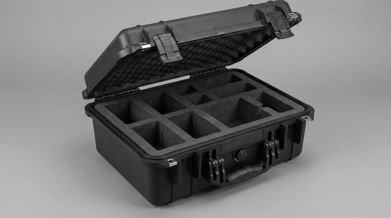
Brackets are difficult because they carry many features at high count. A spring hanger bracket, an engine mount bracket and an anti-roll bar bracket each typically combine mounting holes, a bushing bore, a bolt seating face and a weld seam.
Three ways to protect a hole. First, insert a PE or rubber plug sized to the lower hole tolerance so it stays put under vibration. Second, fit a thin-wall sleeve over reamed or bushed bores, with the sleeve inner face kept clear of the finished bore. Third, wrap the chamfered hole mouth with strippable film. True-position tolerance is typically in the φ0.5 to 1.0 mm band under GB/T 1184, and any burr consumes that margin directly.
Machined faces. Bolt seating faces and bearing-seat planes take a self-adhesive protective film of PVC or PE at 0.05 to 0.08 mm. The film is peeled at the assembly station. Where flatness is gauged on the same face, the film thickness has to be accounted for so it does not shift the gauge datum.
What must never be done. Brackets must not be stacked directly on one another. They must not be threaded onto a wire in batches. They must not share a cavity with rails. The correct method is one part per pocket with a 5 to 10 mm foam divider between pockets.
Left/right and batch identity. Label each pocket lid with part number, hand orientation, batch and production date, positioned so it is visible the moment the case is opened.
5. Chipping and Abrasion Control on Welded and Painted Surfaces
Surface condition drives rework before assembly, and coating damage has two sources: friction against liner or wall, and stress concentration at edges.
A reference for coating chip resistance. The stone-chip and scratch resistance of an automotive coating can be benchmarked against a SAE J400 type gravelometer test, which returns a spalling grade for comparing paint systems. That comparison belongs in the coating specification, not in routine packaging verification. The packaging counterpart is simply this: the liner must be softer than the coating.
Liners softer than the finish. Contact surfaces for painted parts should be EVA or XPE closed-cell foam at Shore A 25 to 40. These materials yield before the coating does. If the liner is harder — an HDPE sheet laid directly against a painted face, for example — the coating is abraded over every vibration cycle.
Where edges need help. Rail ends, the junctions where bracket gussets meet, and weld reinforcement are the three stress risers. Fit corner guards or local foam strips at least 8 mm thick, extending at least 30 mm either side of the edge.
Weld zones. Weld reinforcement is comparatively brittle, and repairing a knock means re-grinding and re-painting. For weld-dense brackets, relieve the liner so the weld bead sits in a void rather than taking load.
Prohibited contact. Do not leave plasticiser-migrating soft PVC in prolonged contact with topcoat. Do not tape directly to topcoat for fixing purposes; removal can lift the film.
6. Liner Material Selection and Hardness Matching
The liner is the performance core of a chassis frame case. Selection turns on compression set, rebound speed and temperature range — not simply on softness.
| Liner material | Typical density / hardness | Where it fits | Watch-outs |
|---|---|---|---|
| --- | --- | --- | --- |
| EVA closed-cell foam | 30–50 kg/m³ / Shore A 25–40 | Rail support blocks, end buffers | Low compression set; best long-term load bearing |
| XPE cross-linked foam | 28–40 kg/m³ / Shore A 25–35 | Bracket dividers, flat pads | Fine skin, coating-friendly; modest tear strength |
| Moulded PU foam | 50–90 kg/m³ / Shore A 30–45 | Contoured pockets for odd-shaped brackets | Complex cavities in one shot; higher water uptake |
| HDPE sheet | 8–12 mm thick | Base plates, partition frames | Stiff; never lay it directly on a painted face |
| EPP bead foam | 30–60 kg/m³ | Large buffers, recyclable programmes | Good rebound; strong economics over many cycles |
Thickness rule of thumb. The cushion layer must satisfy two conditions at once: 10 to 20 percent compression under static load, and no rupture under the drop case. For units above 20 kg, rail support pads of 25 to 40 mm are appropriate. For brackets under 10 kg, 10 to 20 mm dividers are enough.
Machining versus moulding. Low volume with frequently changing geometry suits CNC-cut EVA assembled from layers. Stable volume with complex cavities justifies a mould for PU or EPP, where unit cost falls steeply with quantity.
Cleanliness. Blow debris out of the liner before loading. Closed-cell foam does not absorb water but does hold dust on its skin, and trapped dust becomes the abrasive that scores a painted face.
7. Compartmentalisation, Strapping and Displacement Limiting
Zoning and positive location dictate how much freedom remains inside the case, and that freedom decides whether the hole datum survives the trip.
One part per pocket. Populate one pocket with one part and leave a 3 to 5 mm handling clearance to the pocket wall so loading and unloading does not scrape. Multiple parts in one pocket are acceptable only for small, regular items, and then only with an interlayer divider.
When strapping is required. For rails or one-piece bracket assemblies above roughly 30 kg, add polyester webbing over and above the liner's mechanical location. Use 25 mm webbing rated at not less than 1200 kg breaking strength, routed clear of holes and machined faces, bearing only on non-functional areas.
Three forms of positive location. Liner bosses that cradle by form, location pins that engage a mounting hole (with a protective sleeve), and end stops that block axial travel. Pin location is the most precise, but the pin-to-hole fit must be checked so it cannot score the bore wall.
Displacement acceptance. After vibration testing, relative movement of each part from its initial position should not exceed 2 mm, with no rattle audible from loose contents. This is the direct check on whether location is working.
Handling ergonomics. Do not design an interference fit. A liner that has to be levered apart adds damage risk at every unpack. Aim for a part that can be lifted out by hand, with finger reliefs moulded into the pocket base where needed.
For hinge, latch and gasket interface tolerances on the case itself, the case hinge, latch and seal structure notes give seal compression guidance that applies equally to long-component cases.
8. Corrosion Control: VCI, Desiccants and Barrier Film
Corrosion risk on chassis components is driven almost entirely by ocean transport. Container temperature cycles between roughly 5 and 45 degrees Celsius while relative humidity stays above 85 percent, and salt deposition on the steel surface drives electrochemical attack even before the dew point is reached.
A three-layer approach. Layer one is the part's own surface treatment — e-coat, zinc plating, or phosphate plus preservative oil. Layer two is volatile corrosion inhibitor material generating a protective atmosphere inside the sealed volume. Layer three is desiccant, absorbing residual moisture and holding the humidity down.
Choosing the VCI material. Inhibitor film should meet the requirements of GB/T 16267 for vapour-phase rust-preventive plastic film. It must either wrap the parts completely or line the case interior; the better the case seal, the longer the inhibitor concentration holds. For brackets carrying a zinc layer, confirm the inhibitor chemistry is compatible with zinc, otherwise white rust can worsen rather than improve.
Sizing the desiccant. The working method is to calculate from the free internal volume and the moisture-vapour transmission rate of the barrier film. A common order of magnitude is 1 kg of silica gel per 1 to 2 cubic metres of free volume, taking the upper figure for a 45 day ocean transit. Fit an indicator card wherever contents are exposed to view.
Reference testing. Neutral salt spray can be run to GB/T 10125 or ISO 9227, with rating per GB/T 6461. As a rule of thumb, white rust appearing on zinc-plated parts between 48 and 72 hours is tolerable, while red rust on bare steel within 24 hours signals the protection is insufficient. A closer proxy for a real voyage is the cyclic corrosion test to ISO 14993, whose wet-dry alternation exposes defects that a single salt spray exposure can mask.
What happens after unpack. Inhibitor protection decays quickly once the case is opened. Parts should move into assembly, or be re-oiled, within a defined window rather than sitting in a damp workshop.
9. Sealing, Pressure Equalisation and Temperature Range
The seal rating decides whether the corrosion plan can work at all. If the case cannot keep external moisture out, inhibitor and desiccant only delay the inevitable.
Where to set the rating. Chassis frame cases normally sit between IP55 and IP67 under IEC 60529 or GB/T 4208. IP55 covers rain and hose spray, while IP67 suits a port yard where short-term water accumulation is possible. Match the rating to the actual route rather than defaulting to the highest number, which costs money and makes the case harder to open and close.
Why pressure equalisation matters. A sealed case develops a differential across temperature swings. Under negative pressure the latches become hard to release and the gasket can be drawn inward. A pressure equalisation valve — venting air while blocking liquid water — resolves this while preventing the breathing cycle from repeatedly pulling moist air in. The case pressure equalisation valve note covers the mechanism.
Gasket material and temperature. Silicone gasket stock covers a wide band, roughly minus 50 to plus 200 degrees Celsius. EPDM weathers well but rebounds more slowly in the cold. Where a shipment may transit a severe winter region, verify the design against MIL-STD-810H Method 501.7 (high temperature) and Method 502.7 (low temperature). Note that the standard is used here purely as an environmental test basis and does not constitute a military certification.
Foam behaviour when cold. Standard EVA stiffens noticeably below minus 20 degrees Celsius and loses cushioning capacity. If the route crosses a cold region, specify a low-temperature EVA grade or EPP, and add cushion thickness to offset the rise in stiffness.
10. Lifting, Stacking and Centre-of-Gravity Control
Chassis frame cases are heavy freight, and a loaded case can exceed 200 kg, so lifting and stacking carry as much risk as vibration.
Centre of gravity. The length of a rail spreads mass along one axis, and lateral offset is the part people forget. Keep the combined centre of gravity within 50 mm horizontally of the case's geometric centre, and mark the actual centre and the lifting points on the outside.
Lifting points. Prefer a four-point lift with a spreader beam, which avoids the bending moment a single-point lift introduces. If a forklift is used, match the fork pocket centres to common fork spacing and line the pockets with metal inserts against repeated wear.
Stacking strength. Run static stacking to GB/T 4857.3, at not less than three tiers for 24 hours. Acceptance is no collapse of the case, no permanent crush in the liner, and no contact between parts. Actual stacking inside an ocean container may be higher, so confirm the real arrangement with the customer and re-check.
Pallets and fumigation. Timber pallets must meet ISPM 15 phytosanitary treatment and carry the mark. Plywood pallets are exempt from fumigation and are simpler for export.
Where stiffness needs adding. The weak points on a long case are the mid-side wall and the mid-section of the base. Ribs or an embedded metal frame address this, but re-check the weight penalty against handling.
11. Test Basis and Outgoing Inspection Items
A packaging design should be anchored by test data rather than assertion. The table below lists the tests commonly applied to chassis frame cases.
| Verification item | Standard referenced | Severity applied | Pass criterion |
|---|---|---|---|
| --- | --- | --- | --- |
| Rail movement under vibration | GB/T 4857.23 / ASTM D4169 / ISTA 3E | 30 to 60 minutes on each of three axes, Grms taken from road and rail profiles | Relative shift of any rail stays within 2 mm and every support block remains intact |
| Case drop resistance | GB/T 4857.5 | One corner, three edges and all six faces, drop height selected by gross mass | No rupture through the wall and no bend introduced into a rail |
| Static compression | GB/T 4857.3 | Three loaded cases for 24 hours | Case holds its shape and pad setback after unloading stays inside tolerance |
| Salt spray exposure | GB/T 10125 / ISO 9227 | 48 to 96 hours of neutral fog | Grade assigned to GB/T 6461, with no red corrosion |
| Wet-dry cycling | ISO 14993 | Repeated condensation and drying phases | No blister formation and no film detachment |
| Thermal and humidity cycling | MIL-STD-810H Method 507.6, applied as a test basis only and not a military certification | Follows the agreed transport profile | No standing condensate and no change in gasket hardness |
| Sampling inspection | GB/T 2828.1 | AQL fixed by lot size | Length, pocket geometry and hole guard count all conform |
First-article sign-off. At first article, supply the pocket drawing, material certificates and the test reports listed above, and attach them to the technical annex. Production lots then re-verify the critical items by sampling.
Records to retain. Keep loading photographs, desiccant batch numbers and VCI film batch numbers per lot, so a corrosion dispute can be traced quickly.
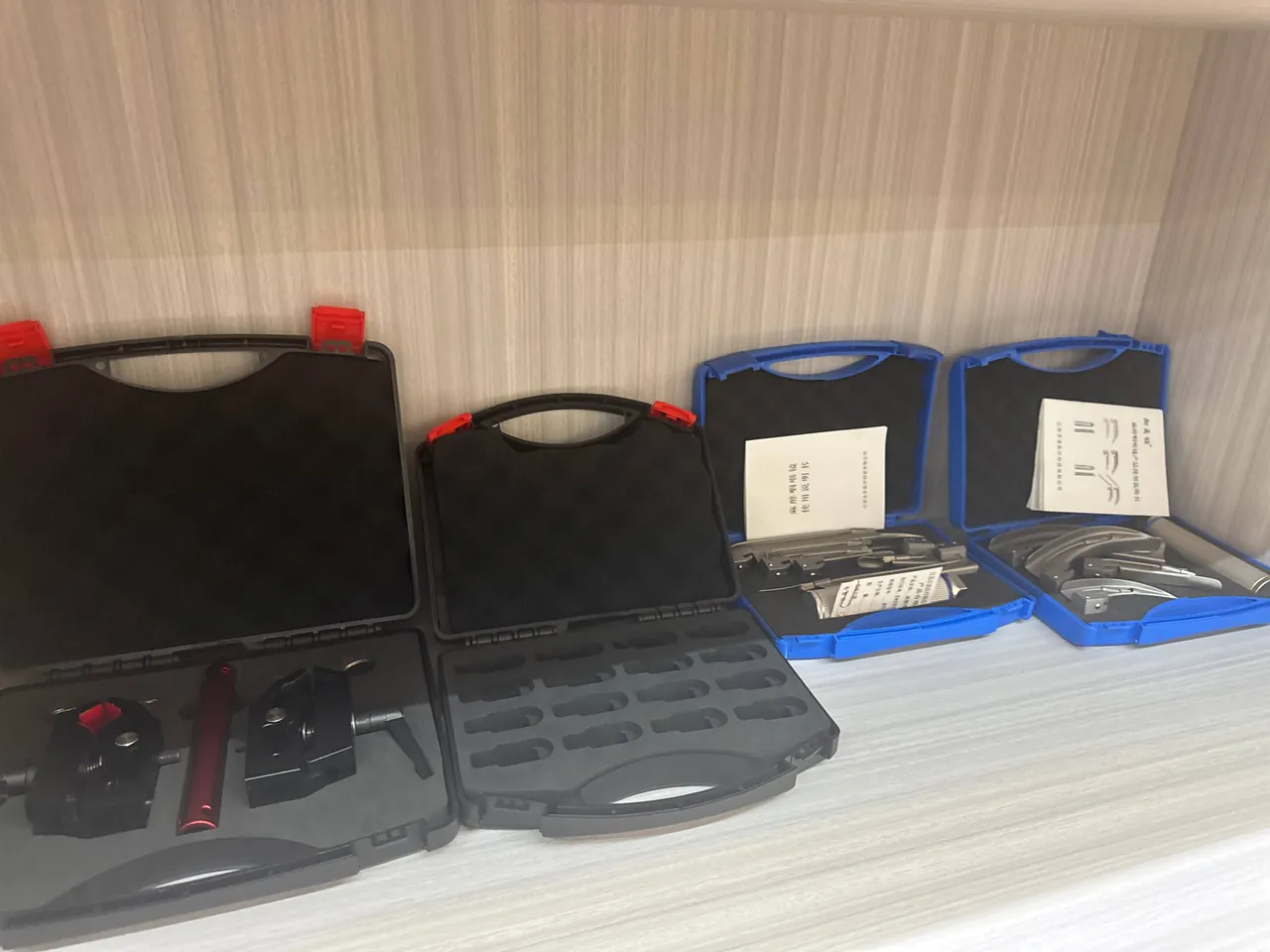
Aligning with general transit packaging requirements. Export programmes frequently have to satisfy both the GB/T 4857 series and a customer-specific distribution cycle, and the transit packaging test methods note is a useful way to consolidate the test matrix.
12. Standard Packing Workflow
Even a good design depends on shop-floor discipline. The steps below belong in the work instruction, illustrated and posted at the packing station.
Step one: count and inspect. Verify part number, quantity and hand orientation, and inspect coating and machined faces for incoming damage. Quarantine incoming defects rather than loading them.
Step two: clean. Remove oil and swarf from machined faces with a lint-free cloth and neutral cleaner. Swarf is the leading abrasive responsible for coating scores and must be completely removed.
Step three: apply corrosion protection. Coat bare faces with preservative oil or confirm the e-coat is intact, and inspect zinc-plated parts for white rust.
Step four: fit liner and guards. Install support blocks and dividers, confirm hole plugs and corner guards are seated, and check the liner for residual debris.
Step five: locate and strap. Load rails in the prescribed orientation with the section opening downward, load brackets one per pocket, and strap anything overweight with a soft pad between webbing and part.
Step six: record. Photograph the loaded state and log part number, quantity, operator and time.
Step seven: desiccant and inhibitor. Place the calculated desiccant charge, keeping it off painted faces.
Step eight: close and label. Confirm the gasket is not twisted or pinched, latch everything down, and apply centre-of-gravity, lifting point, moisture and stack-height labels.
13. Case Size Selection Reference
The table below gives an indicative selection by rail length. Final configuration still depends on unit mass and transport mode.
| Rail overall length | Recommended internal length | Support points | Liner recommendation | Pieces per case |
|---|---|---|---|---|
| --- | --- | --- | --- | --- |
| Up to 3.0 m | 3.2–3.4 m | 3 | EVA 30 kg/m³, 25 mm pads | 2–4 |
| 3.0–6.0 m | 6.2–6.5 m | 4–5 | EVA 35–40 kg/m³, 30 mm pads | 1–2 |
| 6.0–9.0 m | 9.3–9.6 m | 6–7 | EVA 40 kg/m³, 35 mm pads | 1 |
| 9.0–12.0 m | Sectional or purpose-built frame case | 3 per section | EVA plus embedded metal frame | 1 (usually a frame case) |
Rails beyond nine metres. A rail longer than about nine metres rarely suits a monolithic case. Workable options are sectional packaging with a site alignment fixture, or a frame case with a metal skeleton and lifting points at both ends. Confirm the lifting arrangement with the receiving site before committing.
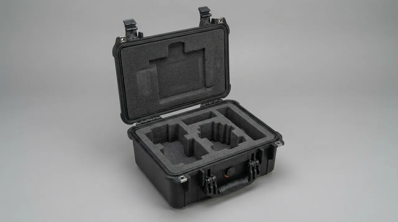
Bracket cases. Brackets are usually handled as a tray-style case with a moulded liner per part family, and 20 to 60 pieces per case is an economical band. When part numbers are mixed, separate them physically by pocket rather than relying on labels alone.
Low-volume, high-mix programmes. For prototypes and small batches, a case with interchangeable liner modules lets one shell cover several part families and shortens lead time. For the shell and seal combinations involved, see the portable transit box selection notes.
Manufacturing and supply. The chassis frame cases described here are developed and produced by Kexin New Materials (Guangdong) Co., Ltd. under the JUNZHIJIA brand. Pocket geometry can be tooled to a specific rail section and bracket hole group, and both build-to-print and co-design models are available. Export volumes can ship as full containers, and regional distribution and agency arrangements are supported. Material certificates, dimensional reports and salt spray records within the contracted scope can travel with the shipment.
Frequently Asked Questions (FAQ)
Q: What deformation pattern is most common on rails in transit, and how does packaging prevent it?
A: Rails are classic slender open-section members, and their torsional stiffness is far lower than their bending stiffness. The typical outcome is therefore not a visible crease but a gradual bow along the length combined with the section splaying open, caused by self-weight acting against support reactions rather than by a single impact. Three measures address it. First, move from two end supports to four or more, spacing supports at 1.2 to 1.5 m so mid-span deflection falls from millimetres to under one millimetre. Second, change the resting orientation so the section opening faces downward, reducing the splay caused by lateral pad pressure. Third, leave 50 to 80 mm of buffer to the case wall, filled with a foam end block that is snug but not compressed hard, so the end cannot hammer the wall. Where straightness is tightly specified, add a temporary spreader inside the channel with soft sleeves at both ends; overall rigidity rises markedly once the case is closed.
Q: Brackets come in large quantities with irregular shapes. How do we stop them damaging each other?
A: The governing principle is to eliminate direct part-to-part contact rather than to add more cushioning material. Use a compartmentalised liner with one part per pocket and a 3 to 5 mm handling clearance to the pocket wall, then place a 5 to 10 mm XPE or EVA divider between pockets. Divider hardness should match the surface condition of the part: as-cast black surfaces tolerate a thinner divider, machined and painted surfaces do not. Bushed and reamed bores take a PE plug or a thin-wall sleeve, with the sleeve inner face kept clear of the finished bore. Never stack brackets directly, never thread a batch onto a wire, and never share a cavity between brackets and rails. Left and right variants look similar but differ in hole pattern, so give each pocket a one-to-one label positioned where it is seen immediately on opening. That single measure removes most mis-assembly rework before it starts, provided the labelling survives the trip and remains legible in a dim warehouse.
Q: Rail hole tolerances are tight. What specific protection does the packaging need?
A: Holes are functional datums, so protection works at three levels. The first is inside the hole: fit plugs or sleeves to mounting and bushing bores, sized to the lower hole tolerance so they survive vibration without pressing on the bore wall. The second is the hole mouth: the chamfered edge is where impact lands first, so wrap it with strippable film or fit a foam ring around the hole. The third is the datum face: apply 0.05 to 0.08 mm self-adhesive film to bolt seating faces and bearing-seat planes, peeling it at assembly. Where flatness is verified with a gauge, account for film thickness in gauge calibration. Restraint is equally important. Hole misalignment usually means the whole part moved rather than the hole being damaged, so lock the degrees of freedom with liner bosses and end stops, and treat a post-vibration relative displacement of no more than 2 mm as the acceptance criterion for effective location.
Q: For shipments to Europe or the Middle East, how should the corrosion protection be designed?
A: Ocean transit combines high humidity, airborne salt and temperature cycling, so the answer is a layered design. At part level, keep the e-coat or zinc layer intact and oil any bare steel. At package level, use volatile corrosion inhibitor material to build a protective atmosphere inside the sealed volume, selecting film that meets GB/T 16267 and is compatible with any zinc layer so white rust is not aggravated. Size desiccant from the free internal volume and the barrier film's moisture-vapour transmission rate, using roughly 1 kg of silica gel per 1 to 2 cubic metres of free volume and taking the upper figure for a 45 day transit. For verification, GB/T 10125 or ISO 9227 neutral salt spray is a fast screen, but ISO 14993 cyclic corrosion testing is the better proxy for a real voyage because its wet-dry alternation reveals blistering defects that a single salt spray exposure can hide. Remember that inhibitor protection decays quickly on opening, so parts must move into assembly or be re-oiled within a defined window.
Q: Does the case need to be IP67 sealed, and will that hurt ease of opening?
A: Match the rating to the route rather than defaulting to the highest grade. For routes dominated by road, rail and conventional cargo holds, IP55 handles rain and hose spray, and because gasket compression is lower the hinges and latches operate smoothly. Only where a port yard exposes the case to short-term standing water or washdown does IP66 or IP67 become justified. Note that a high seal rating introduces a pressure equalisation problem: temperature swings create a differential, negative pressure makes the latches hard to release, and the gasket can be drawn inward and deformed. The remedy is a valve that vents air while blocking liquid water, relieving the differential without letting the breathing cycle pull moist air in. Gasket material also has to suit the temperature band. Silicone covers the widest range, while EPDM weathers well but rebounds slowly when cold. For severe winter routes, verify against MIL-STD-810H Methods 501.7 and 502.7, understanding that this is an environmental test basis and not a military certification.
Q: How do we choose between EVA, XPE and moulded PU foam for the liner?
A: Each material has a clear role, and the choice follows cavity complexity and production volume. EVA closed-cell foam has low compression set and holds its rebound under sustained load, making it the right choice for rail support blocks and end buffers, typically at 30 to 50 kg/m³ and Shore A 25 to 40. XPE cross-linked foam has a fine, coating-friendly skin that suits bracket dividers and flat pads, but its modest tear strength rules it out of load-bearing duty. Moulded PU foam forms complex cavities in a single shot, which suits contoured liners for odd-shaped brackets, though its higher water uptake means it must be paired with desiccant on ocean shipments. On processing, low volume and frequently changing geometry favour CNC-cut EVA assembled in layers, while stable volume with complex cavities justifies tooling for PU or EPP where unit cost falls steeply with quantity. Whichever material is chosen, blow debris out before loading, because closed-cell foam holds dust on its skin and trapped dust becomes the abrasive that scores paint under vibration.
Q: How should lifting and stacking be designed for a rail case?
A: A loaded rail case is heavy freight, and the lifting operation often carries more risk than the voyage itself. Use a four-point lift with a spreader beam to avoid the bending moment a single-point lift creates. If a forklift is used, match fork pocket centres to common fork spacing and line the pockets with metal inserts against repeated wear. On centre of gravity, mass distributes fairly evenly along the rail length but lateral offset is easily overlooked; keep the combined centre of gravity within 50 mm horizontally of the case's geometric centre and mark both the centre and the lifting points on the exterior. Verify stacking strength to GB/T 4857.3 at not less than three tiers for 24 hours, accepting the design only if the case does not collapse, the liner shows no permanent crush and parts do not touch. Actual stacking in an ocean container may be higher, so confirm the real arrangement with the customer and re-check the numbers. Timber pallets need ISPM 15 treatment and marking; plywood pallets avoid fumigation entirely, which simplifies export.
Q: How is a batch of chassis frame cases accepted, and which documents should be retained?
A: Split acceptance into first-article and production stages. At first article, confirm the liner drawing matches the actual parts, that hole guards, corner guards and location features are complete and can be handled comfortably, and obtain material certificates plus key test reports. The usual test set covers random vibration to GB/T 4857.23, ASTM D4169 or ISTA 3E, drop to GB/T 4857.5, stacking to GB/T 4857.3, and neutral salt spray to GB/T 10125 or ISO 9227, with ISO 14993 cyclic corrosion added where an ocean transit period is specified. At production stage, sample per GB/T 2828.1 to verify key dimensions and appearance, checking specifically for debris in the liner, a twisted gasket and fully seated latches. Retain loading photographs, desiccant batch numbers and VCI film batch numbers for every lot so a corrosion or hole-alignment dispute can be traced quickly. Fixing all of this in the technical annex keeps standards from drifting between lots, and it gives both sides a single reference when a claim has to be settled.
Conclusion and Related Reading
Protecting chassis rails and brackets means solving two different problems inside one case: controlling deflection on a long slender member, and preserving the datums on a large population of small irregular parts. The path is well defined. Support rails at 1.2 to 1.5 m intervals with the section opening downward, compartmentalise brackets one per pocket with guards on every hole, keep liner hardness below coating hardness, stack VCI with desiccant and barrier film for corrosion control, pick the seal rating from the actual route and add a pressure equalisation valve, then pin the whole design down with vibration, drop, stacking and salt spray testing. Written into a technical annex, those measures are what stop chassis components arriving at the assembly line with holes that no longer line up.
Related Reading