

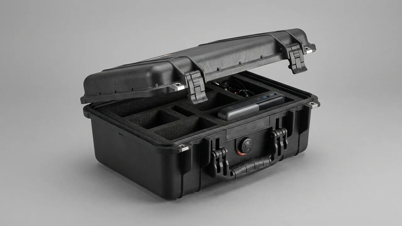
Steering gear belongs to the precision component class of chassis parts, and the classification has nothing to do with size. It follows from a single fact: once a tooth flank corrodes, no repair route exists. Rack teeth in a rack-and-pinion steering gear are ground, with cumulative pitch deviation and profile accuracy measured in microns, and the mesh clearance of the gear pair is set precisely at the factory — steering feel and self-centring both rest on that clearance. Any rust patch on a tooth flank changes the mesh clearance, producing a stiff, noisy or in the worst case sticking steering response. The rack also carries a straightness requirement as a slender member, and bend beyond limit causes eccentric meshing. The design priorities for a steering gear case are therefore a thin, even oil film, a stable low-humidity environment, a conforming and scrupulously clean liner, and cavity separation that keeps electronic parts away from precision flanks.
This article covers racks, gears, rotary valve assemblies, rack ends and EPS electronics separately, with methods for cleanliness control, corrosion protection, liner design, sealing and test acceptance, plus a selection table and packing procedure. The parameters and criteria can be used directly in a technical annex and a goods-inward inspection plan.
Contents
- 1. Why Steering Gear Components Belong to the Precision Class
- 2. How Tooth Flank Corrosion Becomes a Steering Fault
- 3. Protecting Rack Straightness and Pitch Accuracy
- 4. Gears, Small-Module Parts and Rotary Valve Assemblies
- 5. Guards for Rack Ends, Ball Studs and Threaded Sections
- 6. Protecting Dust Boots, Seals and Internal Grease
- 7. ESD and Moisture Protection for EPS Electronics
- 8. Cleanliness Control: Particles, Fibres and Residue
- 9. Corrosion Protection: Thin Oil Film, VCI and Humidity Control
- 10. Liner Materials and Conforming Cavity Design
- 11. Sealing and Pressure Equalisation
- 12. Test Basis and Goods-Inward Acceptance
- 13. Packing, Labelling and Unpacking Practice
- 14. Choosing a Case and Liner for Steering Gear
- Frequently Asked Questions (FAQ)
- Conclusion and Related Reading
1. Why Steering Gear Components Belong to the Precision Class
Chassis parts are usually split into structural and precision classes by mass and size. Steering gear falls firmly into the second.
The accuracy grade makes rework impossible. Accuracy grades for involute cylindrical gears can be referenced against the GB/T 10095 series, and the small-module gears and rack teeth in a steering gear sit at demanding grades across several parameters. Flanks are ground or finish-milled, with surface finish typically between Ra 0.2 and 0.8 μm. Once corrosion appears on such a surface, the volumetric expansion of the rust lifts the surrounding metal and changes flank topography; grinding it back destroys the profile, so no economically viable repair path exists.
The fit relationships make error transfer highly visible. Mesh clearance, rotary valve axial clearance and the clearance between rack and housing guide bush all sit in the micron range. Change any of them in transit and the driver feels it as steering feel. Feedback of that kind is safety-relevant and subjective, so the threshold for a customer complaint is far lower than for a dimensional deviation.
The functional mix makes protection multi-dimensional. A modern steering gear contains mechanical precision parts, rubber seals, grease and electronic sensors at the same time. Those four families place conflicting demands on the environment: flanks need corrosion protection without any particles, rubber must avoid oil, electronics must avoid static, and grease must stay clean. No single protection logic can cover all of it.
Three design priorities follow: keep a thin, clean oil film on flanks and fits; hold internal humidity low and verifiable; separate the component families physically by cavity.
2. How Tooth Flank Corrosion Becomes a Steering Fault
Understanding the consequence chain is what explains why corrosion control here is a functional matter rather than a cosmetic one.
Stage one is dulling. In a humid environment flanks first go uniformly dull. Dimensions have not changed and a wipe with preservative oil restores the surface.
Stage two is pitting onset. Local rust patches appear and the micro-peaks beneath them corrode away into shallow pits. Flank topography has now changed, and contact stress concentrates at the pit edges.
Stage three is mesh clearance change. The volumetric expansion of the rust lifts surrounding metal, adding a small increment in tooth thickness. Combined with the original clearance setting, the result is either excessive free play or an over-tight mesh. The classic symptom is a stiff feel with poor self-centring at low speed.
Stage four is abrasive wear and sticking. Iron oxide particles shed from the rust act as abrasive and are repeatedly rolled across the flanks, accelerating wear. If corrosion occurs in the rack guide region it can also cause local sticking, which is a safety-relevant failure.
The governing criterion. Industry practice treats any visible rust patch on a steering gear flank before assembly as a reject, with no credit for wiping it off. The corrosion plan therefore has to aim not at reducing corrosion but at delivering zero rust patches at the moment the case is opened.
That criterion imposes clear packaging requirements: the oil film must cover the flank completely and must not be wiped away; internal relative humidity must stay low for the whole journey; and no hygroscopic material may sit in contact with a flank.
3. Protecting Rack Straightness and Pitch Accuracy
The rack is the longest precision part in a steering gear, and its protection covers both surface and form.
Sensitivity of straightness. A typical rack straightness requirement can be expressed as no more than roughly 0.05 mm over any 300 mm length. Beyond that, the rack runs off-centre in its housing guide, flank contact shifts to one end, wear becomes uneven and sticking becomes possible. Bending in transit comes mainly from single-point support and self-weight sag, plus lateral pressure from other heavy contents.
How to space the supports. Rack support spacing should be no more than 400 to 500 mm, and support pad width should be at least 60 percent of rack diameter to avoid line contact. Leave 20 to 30 mm of buffer at each end so the ends cannot strike the case wall.
Covering the rack flanks. Apply a thin oil film to the flanks, then fit a dedicated flank cover — a half-round engineering plastic channel whose inner wall does not touch the flanks and whose only job is to keep dust off. Never wrap flanks directly in paper or cloth, because the fibres become a scoring agent.
Protecting ends and cut faces. The connecting ends of a rack — the thread or spline that mates with the tie rod — and the unmachined cut ends need separate treatment. Threaded sections take a thread sleeve, splined sections take a spline sleeve, and cut ends take a soft cap. Ends are the first thing to be struck in any impact.
Indirect protection of pitch accuracy. Pitch accuracy itself does not change in transit, but impact and corrosion on the flanks produce an equivalent change in tooth thickness. Protecting flank integrity is therefore the same thing as protecting the usability of pitch accuracy.

4. Gears, Small-Module Parts and Rotary Valve Assemblies
Gears and valve assemblies are small and highly precise, and they are the easiest items to neglect once they are inside a cavity.
Gear protection. Steering gears use small-module helical gears with narrow faces and fragile tip edges. Use a conforming cavity so the gear shaft carries support rather than the flanks, and keep gears out of the same cavity as other metal parts so a tooth tip cannot be peened into a burr. Where the gear is pressed onto a shaft, focus protection on the journals and bearing seats.
Rotary valve assemblies. A hydraulic steering rotary valve consists of a sleeve and a spool with micron-range clearance and extreme sensitivity to contamination. Any particle entering the valve clearance changes steering feel. Valve assemblies therefore need a dedicated cavity with a dust cap, and the cavity liner surface must be free of debris.
Bearings and needle rollers. Needle and thrust bearings in a steering gear are precision items that are easily lost or contaminated when loose. They must have their own compartments located in a blister or foam tray.
Shared logic with measuring equipment. Small-module gears and valve assemblies follow the same packaging logic as metrology standard instrument cases: conforming location, clean cavities and low humidity. Their liner and corrosion practice is worth referencing.
Grouping principle. Split parts along two axes — whether they carry a tooth flank, and whether they contain electronics — producing four groups, each with its own cavity so that conflicting protection requirements cannot interfere with one another.
5. Guards for Rack Ends, Ball Studs and Threaded Sections
End features are the easiest part of a steering assembly to damage, and the most likely to generate a dispute if a guard is missing.
Thread guard forms. Rack end threads and tie rod threads are external, so they take a plastic or metal thread sleeve sized to the thread pitch diameter, run on to cover the full thread without touching the end face. The sleeve should carry a flange so it cannot back out in transit.
Ball stud protection. The taper and thread of a ball stud are both fits, and a damaged taper prevents the joint from locking up after assembly. Use a dedicated cap with a taper-matching groove, moulded in polyurethane or engineering plastic.
Spline protection. Spline fits have small clearance, and a single burr makes assembly difficult. A one-piece push-on sleeve is preferable to a split design that can work loose.
Dust boot interfaces. Racks usually carry corrugated boots at each end, and the interface is a thin-wall clamp structure that deforms if struck. Fit a ring guard over the interface, softer than the clamp material.
Shipping the guard list. Place a guard list inside the case and mark the exterior so quantities can be counted on arrival. Missing guards are a frequent starting point for arrival disputes, and listing them cuts communication cost sharply. For precision layouts with many compartments, use a removable divider system so guards and compartment numbers correspond one to one.
6. Protecting Dust Boots, Seals and Internal Grease
Rubber parts and grease inside a steering gear have their own environmental requirements, and they are easily lost inside a flank-protection mindset.
Corrugated dust boots. A boot is a thin corrugated wall that collapses if crushed and tears if scored. Load it in its natural extended state, never folded or compressed, and reserve its full length in the cavity with nothing stacked above it. Where volume genuinely forces compression, keep it within 30 percent of free length and do not store it that way long term.
Seals. The input shaft seal and rack end seal are lip seals whose lips are sensitive to scoring. Apply a thin layer of compatible grease to the lip before packing so it cannot dry out, and keep guards clear of the lip region.
Keeping grease clean. Steering gears are filled with a specified quantity of grease at the factory, and the case environment must keep dust out. Particles adhering to grease surfaces are carried into the mesh and become abrasive.
The general rule about rubber isolation. Rubber swells in contact with mineral oil, so oiled parts and rubber parts need a physical barrier between them. Where they must share a case, wrap the oiled parts in barrier film.
How temperature affects grease. Heat causes base oil bleed and cold raises consistency. Keep transport temperature within roughly minus 30 to plus 70 degrees Celsius, and where a route crosses extremes, verify at both temperature extremes under MIL-STD-810H Method 501.7 (hot) and Method 502.7 (cold). The standard serves here only as a basis for environmental testing and confers no military certification.
7. ESD and Moisture Protection for EPS Electronics
Electric power steering electronics add an entirely new dimension to the packaging requirement.
Static-sensitive devices. The EPS torque sensor, position sensor and control unit are static-sensitive, with damage thresholds that can be as low as tens of volts. Operator charge and liner friction charging during packing can both cause latent damage — the kind that does not fail immediately but shortens life or shifts parameters. Establish an ESD-protected area to ANSI/ESD S20.20 or IEC 61340-5-1 and carry electronics in antistatic foam or shielding bags, following the practice set out in the ESD shielding case approach.
Suppressing triboelectric charging. Ordinary foams accumulate static charge when rubbed repeatedly against electronics, so electronics cavities should use antistatic EVA or XPE with surface resistivity held in the conductive or dissipative band.
The double hazard of moisture. Moisture harms electronics twice over: through corrosion, and through reduced insulation resistance. Beyond desiccant and inhibitor film, place a humidity indicator card in the electronics cavity specifically.
Vibration and pins. Sensor pins and connector sockets are fragile, and relative movement under vibration fatigues them. Use a conforming cavity to limit displacement to within 1 mm.
Shared logic with motion control products. Protection of EPS electronics follows the same reasoning as for servo motion controller cases, emphasising static control, conforming location and low humidity.
8. Cleanliness Control: Particles, Fibres and Residue
For steering gear, cleanliness is not an optional extra. It is the precondition for both corrosion protection and wear resistance.
Three contaminant classes. Metal swarf and grit from liner machining and case weld spatter; fibres from cartons, cotton cloth and poor-quality non-woven fabric that wrap around flanks and wrap into valve clearances; and residue from tape adhesive, label backing and cleaning agents.
Liner cleaning routine. Blow cut liners with clean compressed air directed outward from the cavity so debris is not driven deeper, follow with a tack roller over the surface, then sample the cavity walls under magnification before loading.
Controlling the working environment. Segregate the precision packing area from general assembly, control personnel movement and floor dust, and have operators wear powder-free gloves and ESD garments so hair and skin flakes do not enter cavities.
Materials that are prohibited. No recycled paper, wood wool or used cotton cloth as filler or wrap; no ordinary office tape to secure liners; and no paper labels inside cavities, which belong on the liner exterior or the case inner wall.
How to verify cleanliness. Sample to GB/T 2828.1 and wipe the cavity wall with white non-woven fabric for visual particle counting. As a working criterion, no visible particles should come off in a single wipe.
9. Corrosion Protection: Thin Oil Film, VCI and Humidity Control
The target for steering gear flanks is zero rust patches, which requires three stacked layers rather than reliance on one.
Layer one is a thin, even oil film. Keep the preservative oil film on flanks between 3 and 10 μm. Thicker films run and collect particles; thinner films leave gaps. Dip or spray then allow to drain, rather than brushing, which produces uneven thickness.
Layer two is vapour-phase inhibition. Use inhibitor film inside the case to build a protective atmosphere, meeting the requirements of GB/T 16267 and compatible with rubber and electronics. Where copper alloy parts are present in the steering gear, confirm the inhibitor chemistry is non-corrosive to copper.
Layer three is humidity control. Size desiccant from free volume and barrier film transmission rate. Steering gear cases are small, so the usual order of magnitude is 1 kg of silica gel per 0.2 to 0.5 cubic metres of free volume, taking the upper figure when the voyage lasts 45 days, with a humidity indicator card to support judgement on arrival.
Verification. Neutral salt spray follows GB/T 10125 or ISO 9227, with the result graded to GB/T 6461. The criterion applied to flanks is that no red rust appears within 48 hours. For ocean shipments, add ISO 14993 cyclic corrosion, whose wet-dry alternation exposes coating and oil film defects that a single salt spray exposure can hide. For the vibration and shock side of the verification, the transit packaging test procedure note is a useful structure for assembling the test matrix.
Handover after unpacking. Complete assembly or re-oiling within 24 hours of opening, and re-inspect flanks beyond that window.
10. Liner Materials and Conforming Cavity Design
Precision liner design works on a different principle from structural parts: not clamping down, but cradling by form without touching any functional surface.
| Liner material | Typical parameters | Where it fits | Watch-outs |
|---|---|---|---|
| --- | --- | --- | --- |
| Antistatic EVA closed-cell foam | 30–45 kg/m³ / Shore A 25–35 | EPS electronics cavities, sensor locations | Surface resistivity must sit in the dissipative band |
| Low-hardness EVA | 25–35 kg/m³ / Shore A 18–28 | Conforming rack cavities, gear cradles | High cleanliness demand; blow every cavity |
| XPE cross-linked foam | 28–40 kg/m³ / Shore A 25–35 | Dividing walls, end-of-bank cushions | Smooth face traps dust readily |
| Blister tray (PET / PS) | 0.5–1.2 mm thick | Needle bearings, shims, loose parts | Stiff; specify antistatic grades for electronics |
| Engineering plastic guard (PA / POM) | Wall 1.5–3 mm | Flank covers, thread sleeves, spline sleeves | Deburr and radius the bore; softer than the flank |
| Barrier film (VCI type) | Per GB/T 16267 | Whole-case barrier and wrap layer | Confirm compatibility with copper alloys and rubber |
Conforming cavity logic. The cavity should follow the part's functional datums, such as the rack outside diameter or the gear journal — never the flank. The flank location should be relieved into a recess so the flank hangs free. A single-side clearance of 0.3 to 0.8 mm locates the part without clamping it.
Cavity numbering and error proofing. Where specifications are mixed, number the cavities and tie them to the packing list so similar-looking gears or racks cannot be placed in the wrong pocket. Numbering should be engraved or moulded into the cavity edge, not applied on paper.
The economics of changeable modules. For high-mix, low-volume work, a standard case plus interchangeable liner modules sharply reduces tooling spend. The evaluation criteria for choosing a case supplier are set out in the guide to selecting a protective case OEM factory.
11. Sealing and Pressure Equalisation
A steering gear case is small and its contents are valuable, which actually widens the design space for sealing.
Where to set the rating. Specify IP65 to IP67 under IEC 60529 or GB/T 4208. The reasoning is that precision parts tolerate little humidity, and because the case is small the cost increment for a higher rating is limited.
Why pressure equalisation is needed. A sealed case develops a differential across temperature swings. Negative pressure makes the case hard to open and draws the gasket inward, while the breathing cycle repeatedly pulls moist air in and cancels out the desiccant. A venting valve releases that differential while still barring liquid water, and the case pressure equalisation valve mechanism note explains the mechanism.
Gasket material choice. Silicone gasket stock covers a wide temperature band and takes a low compression set, which suits long storage of precision parts; EPDM weathers well but rebounds more slowly when cold. Target 20 to 30 percent gasket compression — more accelerates permanent set.
Durability across repeated opening. Precision cases are opened and closed repeatedly at the assembly station, so gasket and latches are wear items. Design for at least 500 open-close cycles and set a replacement interval in the maintenance plan.
Combining with an inner barrier. Where humidity requirements are particularly strict, add an inhibitor film wrap inside the sealed case, giving an outer seal and inner barrier, with a humidity indicator card for arrival judgement.
12. Test Basis and Goods-Inward Acceptance
Acceptance for precision parts concentrates on flank condition and fit dimensions, so the checks differ markedly from structural packaging.
| Check performed | Standard referenced | Test condition | Acceptance criterion |
|---|---|---|---|
| --- | --- | --- | --- |
| Vibration exposure | GB/T 4857.23 / ISTA 3E / ASTM D4169 | Each axis run for 30 to 60 minutes | Nothing moves more than 1 mm and no cover comes off |
| Dropped case | GB/T 4857.5 | One corner, three edges, six faces, height by mass | Wall remains unbroken and flanks show no mark |
| Stacked weight | GB/T 4857.3 | Three high for 24 hours | No collapse and no lasting crush in the liner |
| Flank corrosion | Visual check under magnification | Performed the moment the case is opened | Flanks completely free of rust spots |
| Geometry | GB/T 10095 series / sampled | Profiles and tooth thickness re-measured | Values match despatch and no burrs are present |
| Salt fog | GB/T 10125 / ISO 9227 | 48 hours | Rated against GB/T 6461, no red rust |
| Wet-dry corrosion | ISO 14993 | Alternating moisture and drying | Flanks clean and paint free of bubbles |
| Static behaviour | ANSI/ESD S20.20 / IEC 61340-5-1 | Surface resistivity measured | Reading in the dissipative or conductive range |
| Climate cycle | MIL-STD-810H Method 507.6, a test basis only, not a military certification | Agreed profile | No condensate and indicator card unchanged |
How to inspect flanks properly. Do it immediately on opening, because the corrosion state at that moment best reflects what the journey actually did. Cover the full flank length and the root transition, where residue concentrates. If rust is found, do not wipe before judging — record and photograph the original state.
Reading the humidity indicator card. Log the colour change point and compare it against the desiccant sizing calculation. If the card changes colour while desiccant remains, the case sealing is inadequate and the gasket compression and pressure equalisation valve should both be checked.
Counting guards. Verify covers, sleeves and plugs item by item, and record any shortage so a thread damaged at the assembly station can be traced back.

13. Packing, Labelling and Unpacking Practice
Sequence on the packing side. Count parts and inspect incoming flank condition, apply preservative oil to specification and allow to drain, fit flank covers and guards, load into the conforming cavity and confirm the flank hangs free, then add desiccant, indicator card and inhibitor film and close the case.
Five prohibited actions. Never touch a flank with bare hands. Never leave paper fragments or fibres in a cavity. Never let oiled parts contact rubber directly. Never let electronics rub against ordinary foam. Never close a case without blowing the cavities clean.
Labelling. Mark the exterior with model, rack length specification, orientation requirement, moisture warning and stack limit; add an ESD marking on electronics cases. Internal cavity numbers must match the packing list.
Sequence on the unpacking side. Record and photograph the indicator card and desiccant state, remove the inhibitor film, then take parts out by cavity number and inspect flanks immediately. Remove flank covers only when the part reaches the assembly station.
Short-term storage. Keep covers fitted on parts not going straight to the line, and complete assembly or re-oiling within 24 hours. Control relative humidity in the storage area and keep it away from any equipment that generates ozone.

14. Choosing a Case and Liner for Steering Gear
| Component class | Typical length / mass | Recommended liner | Guard priorities | Special requirement |
|---|---|---|---|---|
| --- | --- | --- | --- | --- |
| Rack up to 600 mm | 0.8–3 kg | Conforming EVA cavity, one part per pocket | Flank cover, end sleeves | Support spacing ≤ 300 mm |
| Rack 600–1200 mm | 2–6 kg | Long conforming cavity with mid support | Flank cover, spline sleeve | Support spacing ≤ 400–500 mm |
| Gear and shaft assembly | 0.5–2 kg | Conforming cavity cradling the journal | Journal sleeve, flank cover | Flank free of load |
| Rotary valve assembly | 0.3–1.5 kg | Dedicated dust-free cavity | Dust cap, dust film | Highest cleanliness class |
| Needle bearings / shims | Below 0.5 kg | Blister tray with compartments | Compartment location | Numbered for counting, error proofed |
| EPS sensor / controller | 0.2–1 kg | Antistatic EVA cavity | Shielding bag plus conforming location | Displacement ≤ 1 mm, ESD protected |
Mixed loading principles. Zone by protection class: flanks in one group, rubber in another, electronics in a third, loose hardware in a fourth. Separate groups with rigid or foam partitions rather than relying on labels alone, and always place a physical barrier between oiled parts and rubber.
An economical route for high-mix, low-volume work. A standard case plus interchangeable liner modules, managed with cavity numbering, covers many rack lengths and gear specifications without extra tooling — a good fit for prototypes and small batches.
Manufacturing and supply. Cases for steering gear work are built by Kexin New Materials (Guangdong) Co., Ltd. and carry the JUNZHIJIA brand. Liner cavities and guards can be designed around the rack profile, gear journal dimensions and sensor geometry supplied, either developed from customer drawings or co-designed with the customer. Goods move through bulk wholesale channels, regional agencies and direct export shipments, and the shipment can include liner material certificates, cleanliness sampling records, electrostatic resistance test reports and salt spray or cyclic corrosion records within the contracted scope.
Frequently Asked Questions (FAQ)
Q: Why can rack and pinion parts not be handled to the same packaging standard as ordinary chassis structural components?
A: The fundamental reason is that no repair route exists. A structural part that is knocked or stained can usually be ground back, re-painted and straightened within acceptable cost. Rack flanks are ground, with surface finish between Ra 0.2 and 0.8 μm and profile and pitch accuracy at demanding grades, so once a rust patch forms, its volumetric expansion lifts the surrounding metal and changes flank topography — grinding it back destroys the profile, leaving scrapping as the only option. The second factor is extreme sensitivity of the fits. Mesh clearance, rotary valve axial clearance and rack-to-guide clearance all sit in the micron range, and changing any of them is felt by the driver as a difference in steering feel, which is safety-relevant and subjective, so the complaint threshold is far lower than for dimensional deviation. Third, a modern steering gear contains flanks, rubber seals, grease and electronic sensors simultaneously, and those four families place conflicting demands on the environment, so they must be zoned. General packaging standards simply cannot cover that.
Q: How does flank corrosion develop step by step into a steering fault?
A: There is a clear chain, and understanding it is what justifies a zero-rust-patch target. Stage one is dulling, where flanks go uniformly dull in a humid environment with no dimensional change, recoverable by wiping and re-oiling. Stage two is pitting onset, where local rust patches form and micro-peaks beneath them corrode into shallow pits, so topography has changed and contact stress concentrates at the pit edges. Stage three is mesh clearance change, where the volumetric expansion of rust lifts surrounding metal and adds a small increment in tooth thickness; combined with the original clearance setting this shows as either excessive free play or an over-tight mesh, classically a stiff feel with poor low-speed self-centring. Stage four is abrasive wear and sticking, where iron oxide particles shed from the rust act as abrasive, are repeatedly rolled across the flanks and accelerate wear; if corrosion is in the rack guide region it can also cause local sticking, which is safety-relevant. Industry practice therefore rejects any visible rust patch before assembly, with no credit for wiping it off.
Q: How is rack straightness protected in transit, and how should supports be spaced?
A: A typical rack straightness requirement can be expressed as no more than roughly 0.05 mm over any 300 mm. Beyond that the rack runs off-centre in its housing guide, flank contact shifts to one end, wear becomes uneven and sticking becomes possible. Three mechanisms cause bending in transit: self-weight sag over a single support, mid-span droop where support spacing is too wide, and lateral pressure from other heavy contents. The corresponding measures are to keep support spacing at 400 to 500 mm, or within 300 mm for shorter racks, with support pad width at least 60 percent of rack diameter to avoid line contact, and to leave 20 to 30 mm of buffer at each end so ends cannot strike the case wall. The cavity should be dimensioned from the rack outside diameter so the rack bears on its cylindrical surface rather than on its flanks. Racks should also not share a cavity with other heavy items; where they must, use a rigid partition rather than a foam one, because lateral pressure is what produces bend.
Q: What goes wrong most often with rotary valve assemblies and needle bearings?
A: Contamination and loss, and both force a whole-part rework. A rotary valve consists of a sleeve and spool with micron-range clearance and extreme sensitivity to contamination; any particle entering the clearance changes steering feel. This means a dedicated cavity with a dust cap, a liner surface free of debris, and a routine of blowing each cavity clean and finishing with a tack roller before loading. Needle and thrust bearings are small and numerous, so loose packing loses them or lets foreign matter in; they must have individual compartments located in a blister or foam tray, with quantities counted pocket by pocket. A further common problem is mixing them with other parts, where magnetised needles cling to gear or rack surfaces and are carried into the mesh to form indentations. Split parts into four groups along the axes of whether they carry a flank and whether they contain electronics, give each group its own cavity, put hardware in numbered blister trays, and tie the packing list to cavity numbers so arrival counting is straightforward.
Q: How do EPS electronics change the packaging requirements compared with mechanical precision parts?
A: The main addition is a static control dimension. The EPS torque sensor, position sensor and control unit are static-sensitive with damage thresholds as low as tens of volts, and both operator charge and liner friction charging during packing can cause latent damage — the kind that does not fail immediately but shortens life or shifts parameters. Protection follows ANSI/ESD S20.20 or IEC 61340-5-1, with an ESD-protected working area. Practically this means carrying electronics in antistatic foam or shielding bags, using antistatic EVA or XPE for electronics cavities with surface resistivity in the dissipative or conductive band, having operators wear powder-free gloves and ESD garments, and adding an ESD marking to the case exterior. Moisture is a double hazard for electronics, causing both corrosion and reduced insulation resistance, so the electronics cavity should carry its own humidity indicator card. Sensor pins and connector sockets are fragile structures where relative movement under vibration causes fatigue, so a conforming cavity limiting displacement to within 1 mm is essential.
Q: To achieve zero rust patches on flanks, which layers must work together?
A: No single layer can deliver it; three stacked layers are needed. Layer one is a thin, even oil film in the 3 to 10 μm range — thicker films run and collect particles, thinner films leave gaps — applied by dipping or spraying and allowed to drain rather than brushed, which produces uneven thickness, and covering the root transition completely because that is where residue concentrates. Layer two is vapour-phase inhibition using film that meets the requirements of GB/T 16267 and is confirmed harmless to any copper alloy parts, rubber and electronics in the assembly. Layer three is humidity control, sizing desiccant from free volume and barrier film transmission rate; steering gear cases are small, so the usual order of magnitude is 1 kg of silica gel per 0.2 to 0.5 cubic metres of free volume, taking the upper figure for ocean freight, with a humidity indicator card for arrival verification. For validation, run neutral salt spray to GB/T 10125 or ISO 9227 for 48 hours with a criterion of no red rust on flanks, and add ISO 14993 cyclic corrosion for ocean shipments.
Q: How is cleanliness controlled in a steering gear case, and which materials are prohibited?
A: Cleanliness is not an optional extra for steering gear; it is the precondition for corrosion protection and wear resistance alike. There are three contaminant classes: metal swarf and grit from liner machining and case weld spatter; fibres from cartons, cotton cloth and poor-quality non-woven fabric, which wrap around flanks and into valve clearances; and residue from tape adhesive, label backing and cleaning agents. In process terms, blow cut liners with clean compressed air directed outward from the cavity so debris is not driven deeper, follow with a tack roller, and sample cavity walls under magnification before loading. Segregate the precision packing area from general assembly, control personnel movement and floor dust, and have operators wear powder-free gloves and ESD garments. Prohibited materials include recycled paper, wood wool, used cotton cloth, ordinary office tape, and any paper label inside a cavity — labels belong on the liner exterior or the case inner wall. Verify by sampling to GB/T 2828.1 and wiping cavity walls with white non-woven fabric for visual particle counting.
Q: Does a steering gear case need to be IP67, and is pressure equalisation really necessary?
A: Specify between IP65 and IP67, with the choice driven by route and storage conditions. Precision parts tolerate little humidity, and because a steering gear case is small, the material and process cost increment for a higher rating is limited, so taking the higher band is usually justified in this product family. Pressure equalisation is strongly recommended, because a sealed case develops a differential across temperature swings. Negative pressure not only makes the case hard to open and draws the gasket inward, it also drives a breathing cycle that repeatedly brings external moisture into the case and directly cancels the desiccant, making the zero-rust-patch target unreachable. A pressure equalisation valve balances pressure while blocking liquid water and solves both problems at once. Gasket material should follow storage duration and temperature band: silicone covers a wide band with low compression set and suits long storage, while EPDM weathers well but rebounds slowly when cold. Target 20 to 30 percent compression, since more accelerates permanent set. Because precision cases are opened repeatedly at the assembly station, design gaskets and latches for at least 500 cycles and set a replacement interval.
Conclusion and Related Reading
The core problem for a steering gear case is not cushioning but delivering flanks with zero rust patches and zero impact marks at the moment of opening. The route is well defined. Apply an even 3 to 10 μm oil film and keep flanks hanging free. Build a protective atmosphere with inhibitor film meeting GB/T 16267, then lock humidity down with desiccant sized by volume and a humidity indicator card. Support racks at no more than 400 to 500 mm intervals to hold straightness, guard end threads and splines, and cover flanks with half-round guards. Zone rubber, flanks, electronics and loose hardware into separate cavities, adding static control for electronics. Blow and number every cavity, and tie the packing list to cavity numbers. Written into a technical annex and a work instruction, those actions stop the problem of steering that feels wrong at the assembly line before it can start.
Related Reading