

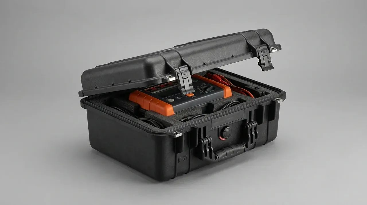
Quick answer: un 38.3 tests the cell and pack, never the shell: eight procedures from 11.6 kPa to 150 g, while the case owes a 1.2 m drop and a 3 m stack.
Table of contents
- What UN 38.3 Puts on the Bench
- Reading T1 to T8 as Eight Different Pressures
- The Three Checks a Case Can Carry
- Insert Geometry: Killing Relative Movement
- Mass, Charge and Where the Report Stops
- FAQ
1. What UN 38.3 Puts on the Bench
A 60 L case for twelve series packs leaves the plant with two documents that never mention each other. One lists eight procedures coded T1 to T8; the other lists three mechanical checks. Teams mix them up and wonder why a lab returns the submission.
Each of the eight clamps a cell or pack in a fixture. The case is not a test article. It is scenery.
| Code | Procedure | Governing value | Failure it hunts |
|---|---|---|---|
| T1 | Altitude simulation | ≤11.6 kPa for 6 h | venting at low pressure |
| T2 | Thermal cycling | -40 to 75 ℃, 10 cycles | seal and tab cracking |
| T3 | Vibration | 7–200 Hz sweep, 3 h | bracket loosening |
| T4 | Shock | 150 g peak, 6 ms pulse | acceleration at the foot |
| T5 | External short | 57±4 ℃ ambient, 1 h | temperature rise |
| T6 | Impact and crush | 13 kN crush force | separator failure |
| T7 | Overcharge | above the maker's current ceiling | run-away |
| T8 | Forced discharge | forced to 0 V | reverse-polarity failure |
Nothing in that table is about a case. Yet T3, T4 and T6 change with how tightly the pack sits: loosen the bay by 2 mm and the pack swings further, so the accelerometer reads higher.
2. Reading T1 to T8 as Eight Different Pressures
The pass criteria belong to the pack. A case maker reads the table for one reason: find the rows that touch the shell.
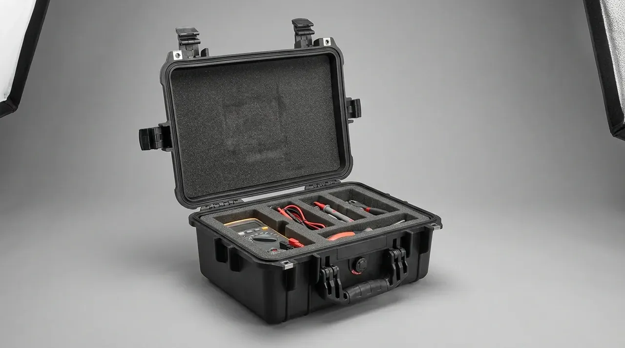
T1 and T2 sit outside the shell. A chamber supplies the 11.6 kPa, an oven the -40 ℃ and 75 ℃ swings, and the case is not even logged as a specimen. T5 follows: the 1 h short at 57 ℃ is wired on a bench, thermocouples on the cell can.
Three rows do reach the shell. The 7–200 Hz sweep in T3 treats the cavity as a first-stage isolator, so wall stiffness decides how much energy reaches the mounting foot. The 150 g pulse in T4 crosses the insert in one hop; foam that is too soft lets a second peak appear, and that peak cracks brackets. The 13 kN crush in T6 asks the wall not to add load of its own — 4 mm to 6 mm moves the bend in the compression curve from about 5 kN out to 8 kN.
T7 and T8 never touch the shell. The case-side rule is negative: keep vents off the lid.
3. The Three Checks a Case Can Carry
The shell still owes three checks, duller than the battery procedures and harder to judge.
The first is a 1.2 m drop, face then edge then corner, one specimen, no substitution. After each impact the case is opened: a through-crack in the wall, a latch out of its catch, an insert that has shifted. The second is a 3 m stack held 24 h, no corner collapse, no permanent set. The third is retention: invert the loaded case for 30 s and the pack stays in its bay.
| Check | Condition | Pass line | Where it fails first |
|---|---|---|---|
| Drop | 1.2 m, face, edge, corner | no through-crack, latches engaged | corner radius whitens, then splits |
| Stack | 3 m for 24 h | corner compression ≤3 mm | base ribs flatten |
| Retention | 30 s inverted | pack movement ≤2 mm | top foam recovers slowly |
Order matters. Drop first, stack second: micro-cracks grow a further 3 mm to 5 mm during the hold. Reverse the two and the harshest stage lands on material that has already crept. We run drop first, three specimens, worst one reported.
4. Insert Geometry: Killing Relative Movement
An insert is not a wrapper. It removes relative movement between pack and wall. A twelve-series pack at 320 mm × 240 mm × 90 mm and 18 kg drops into a bay with 1 mm to 2 mm of clearance per side, and a 3 mm preload from the lid holds it.
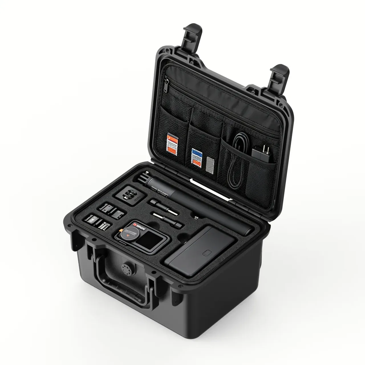
Bay depth runs 85 mm, 5 mm short of the pack, so the lid compresses foam before it meets the lip. Ribs are 8 mm thick, a 10 mm EPE pad sits underneath, corners rounded at 6 mm. After the drop we measure movement against the bay; above 2 mm the answer is a thicker rib.
Foam density is the second lever. EPE at 25 kg/m³ reaches 60% strain under a 150 g pulse and stays there. EVA at 35 kg/m³ returns to 95%, at the cost of pulling force rising from 20 N to 45 N. Past 50 N, operators lever packs out with their fingers and widen the bay.
5. Mass, Charge and Where the Report Stops
Thirty kilograms and a 30% state of charge are not our numbers. The shell must carry that mass through a 3 m stack, which over 8 tiers puts about 0.5 kN on each corner.
Charge level also decides whether the lid can be sealed. A pack at 30% that gets squeezed vents upward, and the lid is the nearest exit. So the lid carries no continuous gasket: two 3 mm relief gaps sit at the ends of the long side, clear of the latches.
The transport assessment and declaration come from a licensed body; the case carries the outer packaging and fixing duty only. Put that in the quotation: the report measures the pack, the shell answers for drop, stack and displacement.
Conclusion
Eight procedures run on the pack, not one on the shell. What the shell can hold is a 1.2 m drop, a 3 m stack and a fixed insert. Get those three right and the acceleration at the mounting foot in T3 and T4 stops doubling; keep 1 mm to 2 mm of clearance and a 3 mm preload, and post-drop movement stays inside 2 mm.
This article covers case-side specifications only and does not address any handling, loading or use of the contents.
Related Reading
- The overall UN certification route
- Structure of a lithium battery transport case
- General rules for dangerous goods packaging
- Cases for retired battery shipments
- How to read a third-party test report
Related Products
- 8 Series — Gun Cases; Military Equipment Cases; Camera Equipment Cases; Drone Cases; Watch Cases; Knife Cases; First Aid Cases; Electronics Equipment Cases
- WL8-2812 PP Gun Case — model WL8-2812
- All protective cases and toolboxes: 7 series, 158 models