

The heart of an abrasive blasting machine is the blast wheel assembly, made up of the impeller, the blades, the control cage, the directing sleeve and the housing. The wheel turns at 2,000 to 3,000 rpm and throws abrasive at 60 to 90 metres per second. That duty gives these parts two contradictory properties at once: outstanding wear resistance and very poor tolerance of impact. Impellers and blades are usually high-chrome cast iron in the Cr26 class, hard enough to reach HRC 58 to 62, with impact toughness often no better than 3 to 8 joules per square centimetre. When a line is relocated, returned to the builder or shipped overseas as a complete package, these parts are frequently stacked on a pallet or loaded bare, and what arrives shows the result: cracked impeller webs, chipped blade corners, a distorted directing sleeve mouth, deformed liner bolt holes, and a balance condition that is only found to be spoiled once the wheel is running with excessive vibration and rising bearing temperature.
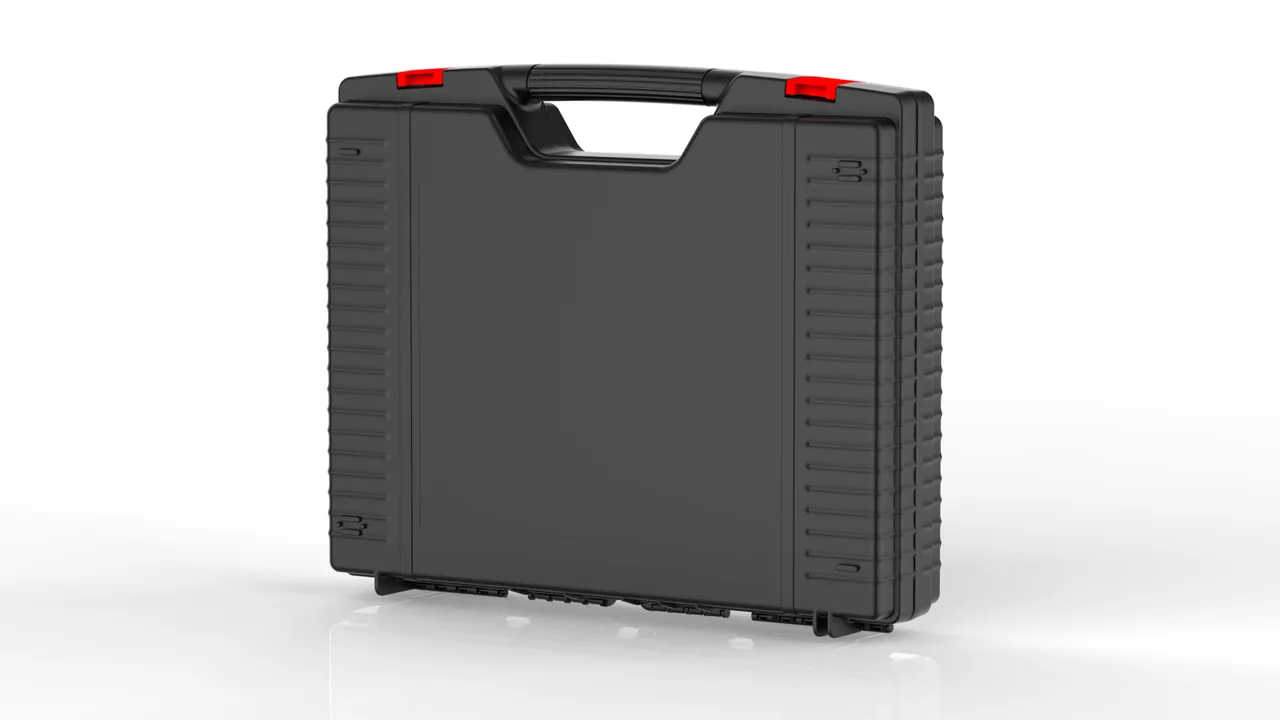
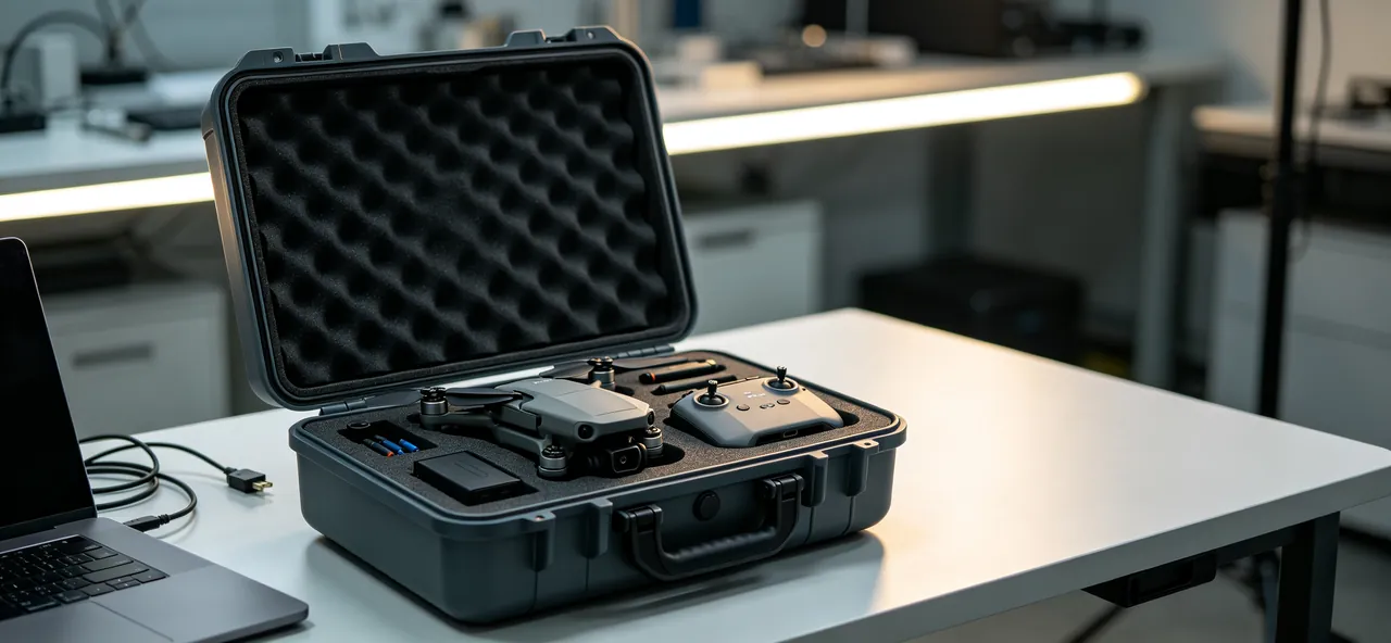
JUNZHIJIA abrasive blasting machine cases work to three limits: heavy parts carry the load, brittle parts have zero freedom to move, and dynamically balanced parts are never shocked. Impellers, blades and directing sleeves sit in their own pockets on soft contact faces, wear liners weighing tens of kilograms each are entrusted to rigid pallets and a reinforced base, and dust filter cartridges travel in a dedicated moisture-controlled compartment. After road and sea transport, the wheel assembly can go straight to assembly without a separate crack inspection.
Table of Contents
- Brittle Failure of High-Chrome Impellers and Blades
- Blast Wheel Housing and Bearing Housing Balance Protection
- Directing Sleeve and Control Cage Mouth Protection
- Heavy Wear Liners: Load Support and Lifting Marks
- Blast Chamber Guard Plates and End Covers in Stacking Support
- Dust Filter Cartridges: Compression and Moisture Packaging
- Bucket Elevator Chains and Separator Anti-Tangle Packing
- Abrasive Valves and Wear Pipes: End-Face Protection
- Axial Location for the Main Gearbox and Bearings
- Moisture and Micro-Crack Control in High-Chrome Castings
- Heavy Case Structure, Lifting Points and Stacking Capacity
- Unpacking Acceptance and Crack Inspection
- Custom Liners, Tooling and Shipped Documentation
Brittle Failure of High-Chrome Impellers and Blades
The impeller is the energy conversion centre of the wheel. Abrasive passes from the control cage into the blade roots and is accelerated along the blades before being thrown. The blade root and the impeller slot are a matched pair, held by centrifugal force and the locating slot once assembled. If impellers and blades are packed together, the blades migrate inside the case and strike the impeller slots, deforming them. A deformed slot prevents the blade from locating correctly, the blade skews in service, the blast pattern moves off its designed track, cleaning efficiency falls and the workpiece shows missed areas.
Pocket design rests on one rule: one blade per pocket, one impeller per pocket. Cut a contoured channel that follows the blade curvature so it is supported along its full length, with stops at both ends to limit movement. Locate the impeller on its outside diameter and centre bore so the web and hub carry the load and the blade slots touch nothing rigid. Never stack impellers and blades, and never bundle them with wire. Wire creates point contacts, and on high-chrome castings a point contact is enough to become a crack initiation site.
| Wheel component | Material and hardness | Sensitive feature | Transit protection focus |
|---|---|---|---|
| --- | --- | --- | --- |
| Impeller | High-chrome iron, HRC 58 to 62 | Web root cracking, slot distortion | Locate on OD and bore, own pocket |
| Blades | High-chrome or composite facing | Corner chipping, root cracking | Contoured channel, full-length support |
| Control cage | High-chrome iron | Window edge wear, chipping | Window inboard, soft facing |
| Directing sleeve | High-chrome or hardened steel | Mouth size and angular accuracy | End ring guard, anti-rotation slot |
| Housing | Cast or fabricated steel | Joint face flatness | Lay flat, joint face up |
| Bearing housing | Casting with machined bore | Bore roundness, coaxiality | Bore plugs, four-point support |
One warning deserves emphasis. Damage to high-chrome parts often appears only after assembly, because an invisible micro-crack propagates rapidly under the centrifugal load of the first run and ends in blade fracture. The aim of transit protection is therefore not that the parts look undamaged on arrival but that no new stress concentration has been introduced, which is why they must not be struck, wire-bundled or left touching steel parts.

Blast Wheel Housing and Bearing Housing Balance Protection
Blast wheels are normally balanced to G6.3, and precision units to G2.5, following the ISO 1940-1 framework. Balance is achieved with weights bolted to specific positions on the impeller. Two transit habits spoil it: shipping impellers and blades separately and reassembling them in the wrong positions, and balance weights working loose under vibration.
Any dynamically balanced impeller should therefore travel as a complete set with its blades, and the blade-to-slot relationship should be marked before packing. Mark on non-fitting surfaces using laser marking or a stamp rather than a paint pen, because paint rubs off in transit. Where separate shipment is unavoidable, mark the impeller and every blade with the same group number and state in the shipped documents that assembly must follow the numbering.
Balance weight bolts should carry a locking washer or thread-locking compound and be re-torqued to specification before packing. Reserve a small pocket for spare weights and bolts, labelled with their mass, so nobody substitutes a bolt of a different weight on site.
Housing and bearing housing joint faces are machined planes, usually flat within 0.05 mm. Lay the housing flat with the joint face upward so the face carries no load, and fit plastic or rubber plugs into machined bearing bores to keep out debris and protect the bore mouth. Support the bearing housing at four points so the bore axis takes no additional bending moment. Where housing and bearing housing are separate parts, arrange them in the case in their assembled relative positions so the site team can cross-check quickly.
On wheels with a water-cooled jacket, drain and blow out the jacket before packing and plug the inlet and outlet. Water left inside will freeze and split the jacket in a cold environment and will corrode the inner wall at normal temperatures.
Directing Sleeve and Control Cage Mouth Protection
The directing sleeve sets the angular position at which abrasive leaves the wheel, and the control cage distributes abrasive to the blades. Together they form a window whose size and angular accuracy determine the shape of the blast pattern. The directing sleeve is adjustable and carries a scale or locating feature on its outside diameter. If the mouth distorts or the locating face is damaged in transit, the pattern cannot be brought to its design position even after assembly.
Protect the mouth and the locating face above all. Fit a soft ring around the mouth, turned from industrial or food-grade EVA, with an inside diameter slightly larger than the mouth so a lateral force meets the soft ring first. Keep the locating face, meaning the scale surface, keyway or dowel hole, facing up so it carries no load. Never nest the control cage inside the directing sleeve to save space. That trick looks efficient but the cage window edges press continuously on the sleeve bore, and vibration turns the contact into repeated tapping, so both edges are damaged at once.
The control cage window edge is the last surface abrasive passes before entering the blades, and the sharper the edge the more focused the blast. Once the edge chips, abrasive distribution becomes uneven, some blades carry more material than others, those blades wear faster and imbalance grows. Place the cage with the windows inboard and the edges clear of any hard surface, with an IXPE facing on the pocket floor.
| Feature | Critical dimension | Typical tolerance | Common damage | Protection action |
|---|---|---|---|---|
| --- | --- | --- | --- | --- |
| Sleeve mouth | Bore and angular position | Bore within 0.2 mm | Ovalisation, chipping | Soft ring guard, face suspended |
| Sleeve locating face | Scale and keyway | Angle within 1 degree | Knocks, keyway distortion | Face up, carries no load |
| Cage window | Window height and angle | Window angle within 1 degree | Edge chipping | Windows inboard, IXPE facing |
| Cage bore | Bore and coaxiality | Coaxial within 0.03 mm | Bore mouth burrs | Plug, own pocket |
Heavy Wear Liners: Load Support and Lifting Marks
Wear liners around the blast chamber and the wheel are the heaviest parts in the set, and although they are not delicate themselves they are the most likely to cause collateral damage. A single high-chrome or high-manganese liner commonly weighs 20 to 60 kg, and a liner that slides or topples inside the case carries enough energy to destroy the adjacent blades, directing sleeve and bearings. The protection goal is therefore to restrain the liner and protect everything else.
Pack liners in a flat stack with interleaved isolation and perimeter restraint. Lay each liner flat, put a 3 to 5 mm rubber or EPE pad between successive plates, and restrain the stack with timber or PP section so it cannot slide horizontally. Never stand liners on edge; even light vibration will topple them. The countersunk bolt holes are the weak point: once a hole mouth is crushed the bolt head cannot sit flush, the liner stands proud and the abrasive flow inside the chamber is disturbed, so keep the countersunk face upward or fit hole plugs.
Liners above 25 kg should sit in their own compartments with lifting information marked on the case. Mark lifting points on the shell in a high-contrast colour and state the gross weight and centre of gravity. On cases heavy enough to need a crane, provide lifting eyes or sling slots at the four corners and make sure the base is evenly loaded during the lift, so the slings cannot press the walls inward and shift the liner.
Base structure must be sized for the heaviest single plate plus the whole liner set. On a mid-size blasting machine the chamber liners can exceed 400 kg in total, at which point a single case is unrealistic and split shipment is the correct answer, with each case numbered and marked for its installation position. The handling discipline used for heavy crushing and screening parts is a useful reference.
Blast Chamber Guard Plates and End Covers in Stacking Support
Guard plates and end covers are large thin-walled flat parts with low stiffness and tight flatness requirements. Once a guard plate bows, a gap opens between it and the chamber wall, abrasive escapes through the gap and erodes the chamber structure, which can be worn through in a short time. End cover bore coaxiality also depends on the flatness of the cover itself, so a bowed cover tilts the bore axis and causes early bearing failure.
For guard plates, the rules are flat, support behind, and no point contact. When plates are stacked, put a full-area EPE sheet of similar size between each pair rather than four corner pads. Corner pads alone let the middle of the plate deflect under stacking load and take a permanent set. Limit stack height, generally to five plates and no more than 200 kg, and use timber pallets to separate layers where necessary.
End covers are circular thin-walled parts, and a vertical slot arrangement suits them best: stand the cover in a slot matched to its diameter so the slot carries the load around the circumference and the faces carry nothing. Standing also means the cover's own weight acts in a different direction from the in-service load, so no additional bending is introduced in the flatness direction. Keep the bearing bore plugged and facing up so nothing falls in.
Covers with a seal groove need particular care, because before assembly the groove must be checked for metal particles and grit; in a blasting plant grit in the seal groove is the leading cause of seal failure.
Dust Filter Cartridges: Compression and Moisture Packaging
Dust collection on a blasting machine normally uses cartridges or filter elements made of pleated polyester or a coated polyester medium. Filtration area is large and the structure is fragile. Two failure modes dominate: radial crushing that deforms the pleat spacing, and moisture uptake that softens the medium and encourages mould. Once pleat spacing deforms, airflow distribution becomes uneven, local velocity rises, captured dust is re-entrained and emission concentration climbs. A damp medium loses strength and tears during pulse cleaning.
Package cartridges vertically, one per pocket. Stand the cartridge in a cylindrical pocket matched to its outside diameter and hold the metal end caps with soft rings, so the caps take the axial load and the pleated medium takes nothing. Never lay cartridges horizontally on top of one another, because the medium deforms under its own weight and adjacent pleats press into each other.
For moisture, bag the cartridge in a clean, dry environment, add desiccant and place the bag in a dedicated moisture-controlled compartment. Size the desiccant to the compartment volume, adjust for routes crossing humid sea areas, and use an indicating grade. Coated polyester media should also avoid long contact with plasticiser-containing film, since migration affects the coating.
Keep cartridges separate from pulse valves and venturis. Diaphragms in pulse valves age quickly at high temperature, and venturi throat accuracy governs cleaning effectiveness and is easily damaged by impact. Both belong in their own labelled pockets.

Bucket Elevator Chains and Separator Anti-Tangle Packing
The bucket elevator moves abrasive from the boot to the separator, and the chain and buckets together determine running smoothness. The most common packing mistake is coiling the chain into a loose bundle, where it presses on itself under its own weight, the link plates and pins take lateral load, and the chain returns to service with elongated pitch.
Coil the chain in a single direction on a spool whose diameter is at least the pitch circle of the sprocket, secure the ends with releasable ties that are snug rather than tight, and never let the runs cross. Long chains should be coiled in sections and numbered separately so the site team cannot connect them in the wrong order. Buckets are thin-walled parts and belong off the chain, laid flat with interleaved isolation. A bucket left on the chain is loaded in a direction it was never designed for and dents easily under the link plates.
The separator combines a cross-flow channel, an adjustable baffle and a return pipe, and its internal air distribution depends on baffle angle and channel wall flatness. Set the baffle to its transport position, usually close to closed, and pin it so it cannot swing during transport and wear the thread or rack of the adjustment mechanism. The inspection window is glass or acrylic and should be film-protected and cushioned on both sides, never loaded directly.
Where the separator has a wear-lined interior, check each lining fixing before packing and include a tightness check sheet asking the site team to re-torque once before first run.
Abrasive Valves and Wear Pipes: End-Face Protection
Abrasive valves and wear pipes are the throttling points of the recirculation circuit, and the accuracy of their end faces and bores decides whether the abrasive feed rate stays stable. Valve plate and seat form a sealing pair with a very small gap. Once the plate is scored or the seat distorts, the valve leaks even when closed, abrasive creeps into the wheel and the blast rate can no longer be controlled.
Ship valves fully closed and locked, or half open with a nylon transport block, so the plate cannot swing and strike the seat. Blank off or cap both flanges to keep out debris and protect the end faces, and pack pneumatic actuators separately so the piston rod is never loaded laterally and bent.
Wear pipes are usually bimetal composite or ceramic-lined. The bond between lining and steel pipe is the most vulnerable feature. Never subject a pipe to bending in transit; support long pipes on multiple cradles at no more than 1.5 m spacing, fit a protective ring at each end, and never let a pipe mouth rest on the ground. Ceramic-lined pipes must not be struck or dropped: ceramic has high compressive strength but poor impact resistance, and a local impact cracks the tile, which then falls out in service and travels with the abrasive into the wheel with serious consequences.
Keep flange bolt holes clean and grease the threads. For long storage, add desiccant inside the pipe and seal the ends so condensation cannot rust the bore.
Axial Location for the Main Gearbox and Bearings
The main gearbox usually connects to the motor through belts or a coupling, and its gears and bearings are precision fits. Gearbox failures after transport seldom come from the gears themselves; they usually come from false brinelling caused by micro-movement. Under vibration the rolling elements slide against the raceways by fractions of a micron, and over time that accumulates into depressions that show up as periodic noise and vibration in service.
Suppressing micro-movement means applying modest axial preload to the bearings and stopping the housing from moving. Fit the maker's transport locking bolts or brackets before packing to fix the input and output shafts, and support the housing at four points underneath with lateral restraint so it cannot slide. Where the gearbox is filled with oil, decide with reference to the maker's instruction whether to keep the level or drain it: a small oil charge helps rust prevention but adds weight and can seep if the case tilts, so the usual compromise is a reduced charge with a sealed plug.
Bearings shipped on their own belong in a vertical or flat locating seat that loads the outer ring and leaves the inner ring free. Shielded bearings must not have the seal lip compressed, and open bearings should be coated in rust preventive and wrapped in moisture barrier film. Keep bearings away from vibration sources, and never ship them in the same case as heavy rotating parts.
Where the gearbox carries an encoder or speed sensor, treat the encoder as a precision optical or magnetic component: pack it separately with shock padding, and disconnect the encoder shaft or fit a flexible coupling so relative movement cannot damage its bearings.
Moisture and Micro-Crack Control in High-Chrome Castings
High-chrome iron is more corrosion resistant than carbon steel, but machined and fitting surfaces still rust in damp storage. Surface rust has little effect on wear performance, yet it hides micro-cracks and removes the inspector's reference. For high-chrome parts, moisture packaging is therefore both a corrosion measure and a way of preserving inspection conditions.
Surface preparation before packing means removing cutting fluid and swarf from machined faces, wiping with anhydrous ethanol or a dedicated cleaner, drying thoroughly, then applying a thin rust preventive oil or VCI film to machined faces. Choose an easily removed oil rather than bitumen-based or heavy wax coatings, because those need solvent washing before assembly, and in practice the washing is rarely complete, so residue carbonises in service and contaminates the abrasive.
Humidity control inside the case comes down to sealing plus indication. Sealing means a moisture barrier film over the liner or a reliably sealed shell. Indication means a humidity indicator card inside, read before deciding whether parts can go straight to assembly. On shipments longer than sixty days crossing humid sea areas, add a separate desiccant compartment so the charge can be changed without opening the main cavity.
Micro-cracks arise from impact, from hydrogen embrittlement and from residual stress, and high-chrome castings retain residual stress from casting and heat treatment, so a transit impact lets a crack start at a stress concentration. Handling with care is therefore a process requirement rather than a courtesy, and low temperature reduces toughness further, so a winter shipment should not be opened and struck while the casting is very cold; the relevant test method is described in an explanation of low temperature brittleness testing.
Heavy Case Structure, Lifting Points and Stacking Capacity
Weights in this application span a wide range. A case of filter cartridges may weigh under 10 kg, while a case of wear liners may exceed 300 kg. Structure must be sized for the heaviest configuration, and lifting must be treated as a primary function rather than an accessory.
| Configuration | Typical payload | Wall thickness | Structural reinforcement | Lifting method | Stacking guidance |
|---|---|---|---|---|---|
| --- | --- | --- | --- | --- | --- |
| Light (cartridges, valves) | 5 to 20 kg | 3 to 4 mm | None or local ribs | Hand carry | 3 to 4 layers |
| Medium (sleeves, cages, pipes) | 20 to 80 kg | 5 to 6 mm | Lateral and longitudinal ribs | Two-person lift or slings | 2 to 3 layers |
| Heavy (impellers, liners, gearboxes) | 80 to 300 kg | 8 to 12 mm | Full frame with metal corners | Corner lifting eyes plus fork pockets | 1 to 2 layers |
| Very heavy (complete wheel assembly) | Above 300 kg | Steel frame design | Steel base frame with removable lid | Base frame lugs plus forklift | Single layer, no stacking |
Stacking calculations must consider the liner and pads, not just the shell. EPE pads under sustained static load lose 5 to 10 percent of their thickness over 30 days, which releases the restraint and allows liners to shift. Heavy configurations should therefore take restraint from timber, PP section or metal corners and use foam only for cushioning and isolation, never as the locating element; the structural principles in heavy duty case design and the load calculations in a guide to case stacking structure are the right references to start from.
Lifting points have to satisfy two conditions: the base is evenly loaded during the lift, and the case does not twist. On long heavy cases, use four lifting points and keep the sling angle at 60 degrees or wider, because a narrow angle generates a large horizontal component that presses the walls inward. Fork pocket positions must account for the centre of gravity, and the exterior should mark the centre of gravity and the upright face.
For testing, run stacking at the real layer count for 24 to 72 hours and drop tests at the height set by weight class, with vibration to the GB/T 4857 series or an ISTA procedure. Note that a drop test on a heavy case often leaves the liner permanently deformed while the shell and parts survive. That outcome, a pass requiring liner replacement, should be agreed in advance and stated in the acceptance criteria, since the liner is a consumable.
Unpacking Acceptance and Crack Inspection
Acceptance of blasting machine components must include crack inspection, and this is what distinguishes it from ordinary equipment acceptance. Micro-cracks in high-chrome parts are invisible to the eye, so blade roots, impeller web roots and control cage window edges should be sampled by penetrant or dye testing. Set the sampling rate by batch size and transport conditions; after a long sea leg or repeated transhipment, inspect all critical parts rather than sampling.
On appearance and dimensions, check impeller-to-blade slots with a feeler gauge and confirm clearance has returned to the design value, re-measure the directing sleeve mouth bore with an internal micrometer within 0.2 mm, check bearing housing bore roundness and cylindricity with a bore gauge, and verify with a template that liner countersinks accept the bolt head fully flush.
On balance, record the dynamic balance data before packing and compare on arrival. If blade numbering no longer matches the impeller, or a balance weight has shifted or its bolt has loosened, rebalance before running rather than installing as found. Rebalancing costs far less than the bearing replacement and housing penetration that follow an unbalanced wheel.
On function, turn the gearbox by hand and check for binding and abnormal noise, confirm the abrasive valve shows no leakage in the closed position using compressed air, check pulse valve operation, and verify that cartridge end caps are undistorted with even pleat spacing. Keep all acceptance records on file with the packing list, balance record and material certificates.
If a visible crack is found in an impeller or blade, replace the part rather than welding it, because field welding of high-chrome iron cannot deliver the required quality and simply introduces a new crack initiation site.
Custom Liners, Tooling and Shipped Documentation
Abrasive blasting machines carry a mixed load of heavy, brittle and precision parts, and a standard liner cannot cover it. Wheel diameters, blade curvatures, sleeve mouth dimensions and liner bolt spacings vary between builders and are rarely interchangeable, so custom work is the only practical route.
The custom process has five steps: supply the parts list with individual weights and centre-of-gravity positions plus 3D models or physical samples; agree the pocket layout, load-bearing method and lifting arrangement; produce the first-article liner and a load-bearing sample case; trial-load and run stacking, drop and vibration validation; and release to volume production. The first-article stage must include a full-load trial, meaning every heaviest part is loaded, so that the deflection of base and lifting points under real weight can be measured. Skipping this step is the main cause of rework on projects of this type.
As the manufacturer, JUNZHIJIA supplies moulded heavy-duty shells, steel base frame design, routed and vacuum-formed liners, lifting point marking, silkscreened position numbers and shipped documentation, with OEM and ODM support and multilingual delivery. The document set normally includes the packing list, pocket layout and centre-of-gravity drawing, material and balance record index, lifting and stacking work instructions, and a critical-part crack inspection record sheet.
Where dust collection components dominate the shipment, the cartridge and hopper packing points in dust collector equipment cases apply; where the parts come from a surface treatment line, the compartment and moisture chapters in surface finishing equipment cases are relevant; and where wear liners resemble mill liners, the support approach used in ball mill liner cases can be borrowed.
Frequently Asked Questions FAQ
Q: Why do high-chrome impellers crack so easily, and how is that avoided in transit?
A: High-chrome iron in the Cr26 class reaches HRC 58 to 62 only by giving up toughness, and impact toughness is typically 3 to 8 joules per square centimetre, which makes it a classic hard and brittle material. It does not bend, it cracks, and the crack often starts from a small internal or surface defect that cannot be seen. The crack then propagates rapidly under the centrifugal load of the first run and ends in blade fracture and housing penetration. Avoiding cracks in transit is a matter of not introducing new stress concentrations. Never bundle impellers and blades with wire, because wire creates a point contact that becomes a stress raiser. Never strike or drop the parts; a fall from 300 mm is enough to start a crack. Never let high-chrome parts touch heavy steel parts directly. Locate the impeller on its outside diameter and centre bore, support blades on full-length channels, separate contact faces with IXPE or soft EVA, and sample impeller web roots with penetrant testing after unpacking.
Q: Can the blast wheel lose its balance in transit, and how is that prevented?
A: Yes, and the damage usually comes from two easily overlooked steps. The first is separate shipment: once an impeller has been balanced, each blade has a defined relationship with its slot, and reassembling them in the wrong positions increases the residual unbalance noticeably, which then shows up as vibration and rising bearing temperature. The second is a loose balance weight: weights are bolted at specific positions, and vibration will move a bolt that has no locking feature. Three measures prevent both. Ship a balanced impeller as a complete set with its blades where possible, and mark the non-fitting surfaces with laser marking or a stamp rather than paint. Fit locking washers or thread-locking compound to the balance weight bolts and re-torque them to specification before packing. Reserve a small pocket for spare weights and bolts, labelled with their mass, so nobody substitutes a bolt of different weight on site. If numbering does not match or a bolt has loosened, rebalance before the wheel is installed.
Q: Wear liners are heavy. What is the real focus of protecting them in transit?
A: The focus is not protecting the liner but restraining it and protecting everything else. A single high-chrome or high-manganese liner commonly weighs 20 to 60 kg, and if it slides or topples inside the case it carries enough energy to destroy adjacent blades, the directing sleeve and the bearings. Pack liners as a flat stack with interleaved isolation and perimeter restraint: lay each plate flat, put a 3 to 5 mm rubber or EPE pad between plates, and restrain the stack with timber or PP section so it cannot slide horizontally. Never stand liners on edge, because light vibration will topple them. The countersunk bolt holes are the weak point, since a crushed hole mouth prevents the bolt head from sitting flush, leaving the liner proud and disturbing the abrasive flow inside the chamber; keep the countersunk face upward or fit hole plugs. Liners above 25 kg deserve their own compartment with lifting marks on the case, and the case should state gross weight and centre of gravity.
Q: What damages dust filter cartridges in transit, and what packaging details matter?
A: The two dominant failure modes are radial crushing that deforms the pleat spacing, and moisture uptake that softens the medium and encourages mould. Deformed pleat spacing makes airflow uneven, raises local velocity and re-entrains captured dust, so emission concentration climbs. A damp medium loses strength, tears during pulse cleaning and has to be replaced far earlier than planned. Pack cartridges vertically, one per pocket, with axial location and load bearing on the end caps: stand the cartridge in a cylindrical pocket matched to its diameter and hold the top and bottom end caps with soft rings so the caps take the axial load and the pleated medium takes nothing. Never lay several cartridges horizontally on top of each other, because the medium deforms under its own weight and adjacent pleats press into one another. For moisture, bag the cartridge in a clean dry environment with desiccant, place it in a dedicated moisture-controlled compartment, and avoid long contact between coated media and plasticiser-containing film.
Q: Can the control cage be nested inside the directing sleeve to save space?
A: No. Nesting the cage inside the sleeve looks like an efficient use of space, but the cage window edges press continuously against the sleeve bore, and vibration turns that contact into repeated tapping. Both edges are damaged at the same time: the sleeve mouth ovalises or chips, and the cage window edges chip. Those two features determine the shape of the blast pattern and the evenness of abrasive distribution, and once damaged the wheel cannot be adjusted back to its design position, so cleaning efficiency falls and the workpiece shows missed areas. Keep the two strictly in separate pockets. Fit a soft guard ring around the sleeve mouth and place the sleeve with its locating face upward and unloaded. Place the cage with its windows inboard and its edges clear of any hard surface, on an IXPE facing. Neither part should share a pocket with steel or heavy components, and neither should be bundled with wire, because a point contact becomes the starting point of a crack.
Q: How should lifting points and stacking capacity be designed on a heavy case?
A: Both are sized for the heaviest configuration rather than the average. On a mid-size blasting machine the chamber liners can exceed 400 kg in total, at which point a single case is unrealistic and the shipment should be split, with each case numbered and marked for its installation position. Lifting points must satisfy two conditions: the base is evenly loaded during the lift, and the case does not twist. Long heavy cases should use four points with a sling angle of 60 degrees or wider, because a narrower angle generates a large horizontal component that presses the walls inward. Stacking capacity must account for the pads as well as the shell: EPE loses 5 to 10 percent of its thickness under sustained load over 30 days, which releases restraint and lets liners shift, so heavy configurations should take restraint from timber, PP section or metal corners and use foam only for cushioning. Mark the centre of gravity and the upright face on the exterior.
Q: Do high-chrome parts suffer from storage in a humid environment?
A: They suffer in two ways. The first is surface corrosion: high-chrome iron resists corrosion better than carbon steel, but machined and fitting faces still rust in damp storage over time. Rust has little effect on wear performance, but it hides micro-cracks and removes the inspector's reference. The second is the effect on inspection itself, since penetrant and dye testing rely on the penetrant showing a clear indication, and rust and oil film interfere enough to cause a crack to be missed. Surface preparation must therefore be complete: remove cutting fluid and swarf, wipe with anhydrous ethanol, dry thoroughly, then apply a thin easily removed rust preventive oil or VCI film to machined faces. Avoid bitumen-based or heavy wax coatings, because they are rarely washed off completely on site and the residue carbonises in service and contaminates the abrasive. Inside the case, combine sealing with indication: use a moisture barrier plus a humidity indicator card read before assembly, and add a separate desiccant compartment for shipments longer than sixty days.
Q: What information is needed to specify a custom abrasive blasting machine case, and how do lead time and documents work?
A: Provide the parts list with names, quantities, materials, individual weights and centre-of-gravity positions; key dimensions with 3D models or physical samples; the tolerance of fitting features such as impeller slots, directing sleeve mouths and bearing bores; balance records where available; lifting and stacking requirements; and the transport route together with whether long-term storage is involved. For export, state the label language required. The sequence is parts list review with a load-bearing layout, first-article liner and sample case, full-load trial with stacking, drop and vibration validation, then production. The first-article stage must load every heaviest part so base and lifting point deflection can be measured; skipping it is the main cause of rework. The shipped set covers the packing list, pocket layout and centre-of-gravity drawing, material and balance index, lifting and stacking instructions and a crack inspection record sheet, with OEM or ODM customisation.
Conclusion and Related Reading
Here the usual rules invert: the harder the part, the more brittle it is. Locate impellers on bore and diameter, support blades along their length, restrain liners with timber and stand cartridges on their end caps. JUNZHIJIA builds shells, base frames and liners to order.
Related Reading