

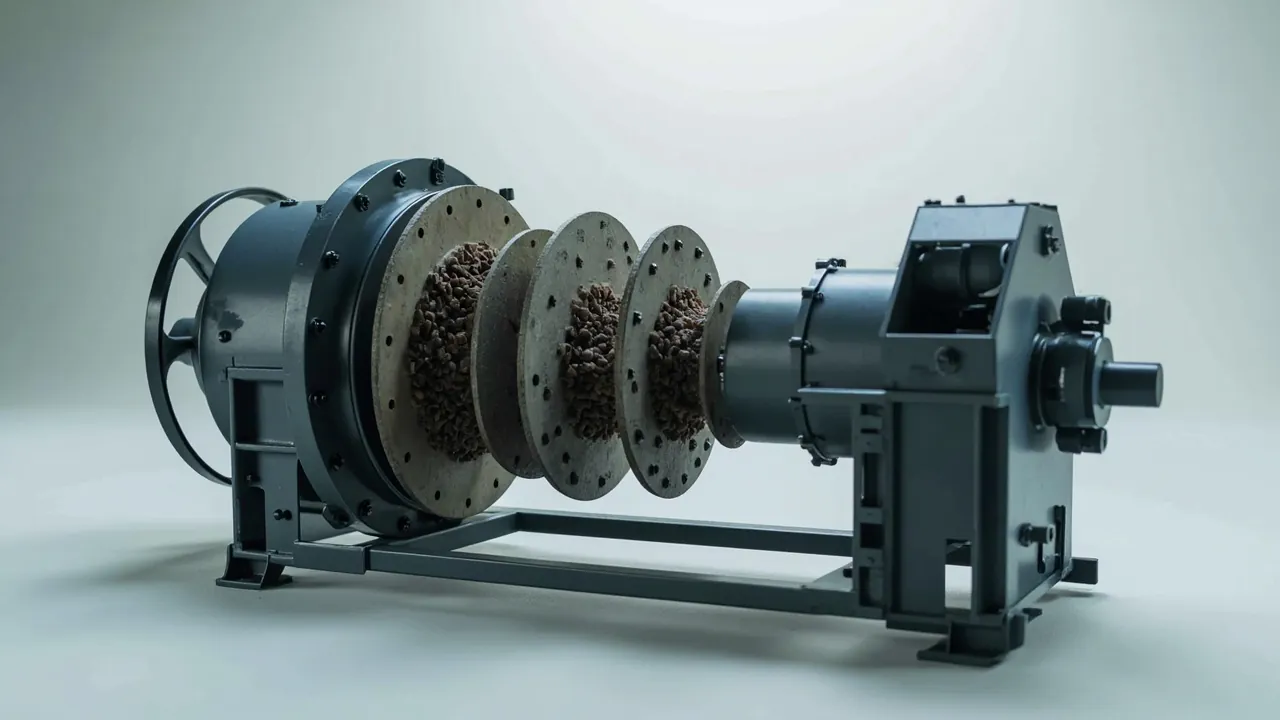
A concentrator typically allows only 7 to 15 days for a ball mill relining shutdown, and the liners plus grinding media must arrive, fit and torque down inside that window. If a liner reaches site with a crushed working face, a distorted bolt hole or a chipped edge, it will not seat against the shell, and the consequence ranges from a return shipment to the whole mill missing its restart date. Grinding media sits at the opposite end of the spectrum: steel balls have a bulk density around 4.5 to 4.8 tonnes per cubic metre, so packing them as ordinary bulk cargo can tear a case apart at the base during handling.
A ball mill parts case therefore has to solve two fundamentally different problems at once. It must hold large plate-shaped liners in a controlled attitude, and it must confine very high density media inside a container that will not collapse. This article works from liner geometry and media behaviour to case structure, liner zoning, moisture protection and an arriving inspection checklist, written for concentrator maintenance departments, mill spare parts suppliers and packaging engineers.
Table of Contents
- How Liners and Grinding Media Differ in Logistics Terms
- Liner Types and Load Paths: Wave, Step, End and Grate
- Containerised Loading Options for Grinding Media
- Separate Protection Lines for Manganese and High-Chromium Liners
- Managing Shell Bolts and Clamping Hardware as Kits
- Lifting Interfaces and Case Connections for Very Heavy Components
- Three-Layer Liner Build: Bearing, Restraint and Energy Absorption
- Corrosion Control in the Wet Concentrator Environment
- Case Load Verification and Stacking Limits
- Sea Freight: Balance, Lashing and Container Layout
- Arrival Inspection Checklist and Test References
- Batch Consistency and Custom Delivery Workflow
- Frequently Asked Questions
- Conclusion and Further Reading
How Liners and Grinding Media Differ in Logistics Terms
Many sites put liners and steel balls in one case on the reasoning that both belong to the ball mill. That works occasionally on short, gentle journeys, but it fails on any road leg beyond 500 km and on any sea leg. The instability mechanisms of the two cargo types run in opposite directions: liners suffer from local point loads, while media suffer from global instability.
A liner is large in area, moderate in thickness, stiff but weak at the edges. A shell liner for a 3.2 m mill might measure 1.2 m by 0.5 m and 50 to 90 mm thick, weighing 80 to 260 kg. It tolerates face loading but its edges and bolt holes are the vulnerable zones, which can lip over or ovalise under pressure.
Media are granular, extremely dense and free-flowing. An 80 mm steel ball weighs roughly 2.1 kg, and a one tonne charge occupies only about 0.22 cubic metres. When those balls can move freely inside a case, any tilt drives the entire mass to one side and generates side pressure far above the static value.
| Item | Unit characteristics | Main failure mode | Constraint direction |
|---|---|---|---|
| --- | --- | --- | --- |
| Shell liner | Large flat plate, weak edges, 80 to 260 kg | Edge lip-over, hole distortion | Face support plus free edges |
| End liner | Curved, irregular, 100 to 400 kg | Curved face deformation | Profile-matched cradle |
| Grate plate | Perforated, thin wall, 40 to 120 kg | Rib fracture between holes | Flat lay with full support |
| Steel balls | 0.5 to 8 kg each, very high bulk density | Global instability, base tearing | Full fill plus rigid container |
| Cylpebs and ceramic media | Angular or brittle, fragile | Corner breakage, spalling | Bagged with cushion layers |
With this table in view the design path becomes obvious. Liners follow a route of face support, released edges and positive restraint. Media follow a route of rigid container, full fill and side-pressure resistance. Both share the same need to solve centre of gravity and lifting, which places them firmly in heavy spare parts logistics, discussed further in the mining and mineral processing parts case guide.
Liner Types and Load Paths: Wave, Step, End and Grate
Mill liners divide into lifting types and grinding types, and the geometry determines the packing attitude directly.
Wave and step liners are lifting types with a continuous raised profile. Their principal asset is that profile, because if the crest is flattened or worn the ball lift height drops and throughput falls with it. During packing the working face must point inward and touch nothing rigid. The usual approach is to place two liners face to face with a 15 to 20 mm rubber interlayer, or to orient faces upward with clear space above.
End liners are curved and irregular, so the centre of gravity is not at the geometric centre. They require a profile-matched cradle whose shape is machined in reverse from the liner's back curvature, spreading stress across the arc rather than concentrating it at the two ends.
Grate plates are thin-walled and perforated, and the rib section between holes is small enough to fracture under compression. Lay them flat with full support, separate layers with rigid boards, and generally keep stacks to four layers or fewer.
The mounting face on the back of a shell liner is a mating surface. It needs protection but not heavy grease, because crews rarely degrease it before installation. A thin film of rust preventive under a wrap is the practical answer.
When several liner types ship together, group them by mill chamber, so that a complete set for one shell section travels in one case. A crew can then open one case and lay out the installation sequence directly, which reduces mis-installation and double handling. This order-of-installation packing logic parallels the thinking in the casting mould transport case reference.
Containerised Loading Options for Grinding Media
Grinding media still leaves many plants in woven sacks with loose stacking. That is acceptable for short in-plant moves but carries real risk once the shipment enters interprovincial or international logistics.
The first choice is a steel or high-strength engineering plastic returnable bin. The walls need enough lateral stiffness to resist the side pressure generated by the fill height. As a practical figure, a one metre column of steel balls produces side pressure in the region of 15 to 20 kPa, and a thin panel will bulge or split. The base needs reinforcement rather than a flat sheet alone.
The second choice is a flexible intermediate bulk container with lifting loops. This suits sites with lifting capability and media that are not oxidation sensitive. Two points matter: specify a safety factor of at least 5 to 1, and ensure the discharge and fill openings are sewn or tied to prevent media loss in transit.
The third choice is compartmentalised media bags. Divide the charge into 25 kg or 50 kg units and place those units inside the case. This makes the media easy to draw down in the required quantity and prevents the whole mass from flowing when the case tilts.
Fill ratio and centre of gravity: media cases should be filled as completely as possible, and any remaining void should be divided into small compartments rather than left as one void. If void space is unavoidable, put it at the middle of the case rather than at one side.
Ceramic and high-chromium media are brittle or very hard and need additional cushioning. Bag them separately with soft interlayers, and never mix them with steel components, because the hardness difference causes mutual gouging.
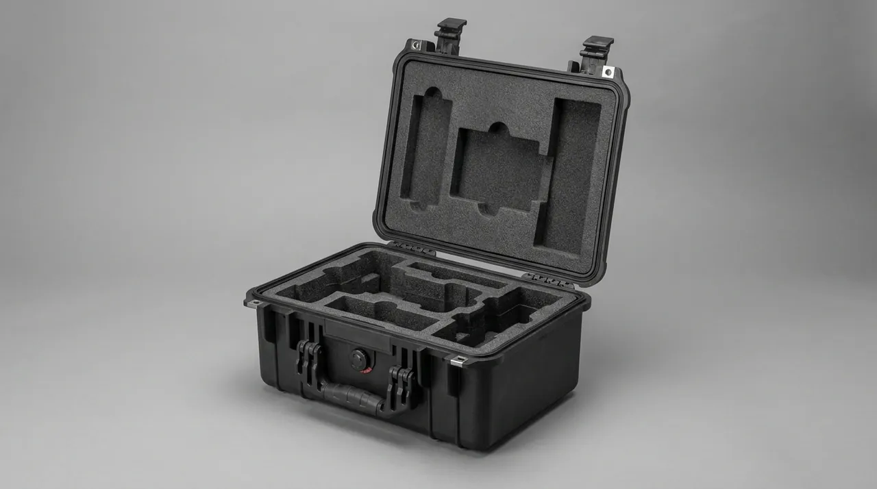
Separate Protection Lines for Manganese and High-Chromium Liners
Liner materials span manganese steel, high-chromium cast iron, alloy steel and rubber or composite constructions, and the four groups have different priorities.
Manganese steel liners are tough and work-harden readily, so the transit risks are surface scratching and edge chipping. The strategy is scratch and moisture prevention: film wrap plus vapour-phase inhibitor, with corner protectors fitted.
High-chromium cast iron liners reach HRC 58 and above with pronounced brittleness. Any corner impact can initiate a microcrack, and once the case is in a vehicle under alternating load, that crack propagates. The priority is impact prevention: compressible corner protectors, and never stacking directly onto the working face.
Alloy and bainitic liners are heat treated and sensitive to surface condition. Where a liner carries a machined or fitted surface, apply rust preventive oil and face protection, and keep it away from direct contact with castings.
Rubber and composite liners are relatively forgiving cargo, but rubber hardens and embrittles at low temperature. For winter long-haul transport, avoid extended exposure below minus 20 degrees Celsius and avoid sustained heavy stacking, which leaves a permanent indentation.
| Material | Hardness range | Main risk | Protection focus |
|---|---|---|---|
| --- | --- | --- | --- |
| Manganese steel | HB 180 to 220 as supplied | Scratching, edge chipping | Film, vapour inhibitor, corner protectors |
| High-chromium cast iron | HRC 58 to 62 | Chipping, microcracking | Compressible corner protectors, no face loading |
| Alloy or bainitic steel | HRC 40 to 55 | Machined surface rust, impact | Rust preventive grease, face protection |
| Rubber or composite | Shore A 60 to 75 | Low-temperature hardening, set | Avoid cold and sustained heavy load |
Managing Shell Bolts and Clamping Hardware as Kits
Mill liner fastening systems comprise shell bolts, washers, sealing rings, clamping wedges and filler, all low in unit cost and highly matched to each other. The most frequent cause of a stalled shutdown is not a missing liner but a missing bolt of a specific length.
The engineering answer is to kit per liner. Assemble the bolts, washers and sealing rings needed for one liner into a single small bag, mark the bag with the liner part number and installation position, then secure it in a dedicated compartment. A crew then has one hardware kit per liner and will not discover a missing washer halfway through a row.
Rubber sealing rings need separate protection against compression and light. A deformed ring loses its sealing function and causes shell slurry leakage. Store rings in small individual boxes with nothing stacked on top.
Thread protection on bolts is often overlooked. Shell bolts generally carry large-diameter fine threads, and handling knocks damage them so they cannot be started on site. Fit a plastic cap to each bolt, or wrap the whole bundle in soft material before restraint.
Present the kit list twice: a detailed list inside the case and a summary list outside, with matching reference numbers. This supports both on-site verification and quick identification during transport.
Lifting Interfaces and Case Connections for Very Heavy Components
Liner and media cases frequently exceed one tonne gross, so lifting interface design is directly tied to handling safety.
Lifting points must land on the primary load frame. A common error is to bolt a lifting eye to a case wall panel, which is typically only 12 to 18 mm thick and will tear out. The correct practice is for the eye base to pass through the panel and fix to a steel load beam or the base frame.
Sling guide channels in the base let slings self-centre when tensioned, preventing the case from tilting during the lift.
Mark the centre of gravity truthfully. A media case has a centre close to its geometric middle, while a liner case can be offset by 100 to 300 mm depending on the liner mix. Mark the actual centre rather than defaulting to the middle of the panel.
Stops and lashing points: fit stops in the base that engage recesses in the pallet or vehicle deck to prevent the whole case from sliding. Lashing points should withstand a horizontal force of at least 0.8 times the case self-weight, which is standard practice for road transport.
Design lifting to a factor of four, and confirm lifting point locations by calculation rather than by experience.
Three-Layer Liner Build: Bearing, Restraint and Energy Absorption
Liners and media need different internal treatment, so handle them through a three-layer framework.
The bearing layer sits at the base and distributes concentrated loads. Liner cases benefit from high-density EVA at 60 to 80 kg per cubic metre or a rubber pad, 20 to 30 mm thick. Media cases carry more uniform loading, so medium-density EVA or a steel base with a rubber facing is sufficient.
The restraint layer determines whether a component can move horizontally. Liners are restrained by side stops and machined pockets, with pocket depth at 15 to 20 percent of liner thickness. Too deep and loading becomes difficult; too shallow and restraint is inadequate. Irregular parts such as end liners are best served by CNC-machined profile pockets.
The energy absorbing layer handles impact. Wrap liner edges and grate plate corners in low-density PE foam at 25 to 35 kg per cubic metre, 20 to 40 mm thick. Media cases do not need a separate absorbing layer, but a compressible sponge layer under the lid suppresses ball bounce.
For machining methods, tolerance control and cost structure of profile liners for irregular parts, see the custom case mould cost analysis.
A practical reminder: liner compression must match lid closure. A liner that is too thick prevents the lid from closing, while one that is too thin leaves insufficient clamping force. Perform a closure trial after liner assembly and measure the gap between lid and case body, targeting 0 to 2 mm.
Corrosion Control in the Wet Concentrator Environment
A concentrator presents a combined corrosion environment of high humidity, heavy dust and sulphide content, which is far more aggressive than a general industrial setting.
Humidity dominates. Relative humidity in a concentrator often sits between 70 and 95 percent, and condensation forms whenever a liner surface falls below the dew point. Once condensation occurs, manganese steel shows visible surface rust within days and high-chromium iron can begin pitting.
The three-part corrosion package is a barrier film, a vapour-phase inhibitor and desiccant. Use PE or aluminium-laminate barrier film, keep the vapour-phase material within 300 mm of the metal surface to maintain effective concentration, and size the desiccant from the internal net volume.
Temperature cycling calls for pressure management. A sealed case stored where day-night temperature swings are large will develop positive and negative internal pressure. Excessive sealing leads to case distortion or gasket failure, and that is the point at which a pressure equalisation valve belongs in the design. Selection logic is covered in pressure equalisation valve for protective cases.
Yard practice matters too. Store cases at least 100 mm above the ground so capillary action cannot draw water up, and ensure no water can pond on the lid. A waterproof top cover is worthwhile where storage is marginal.
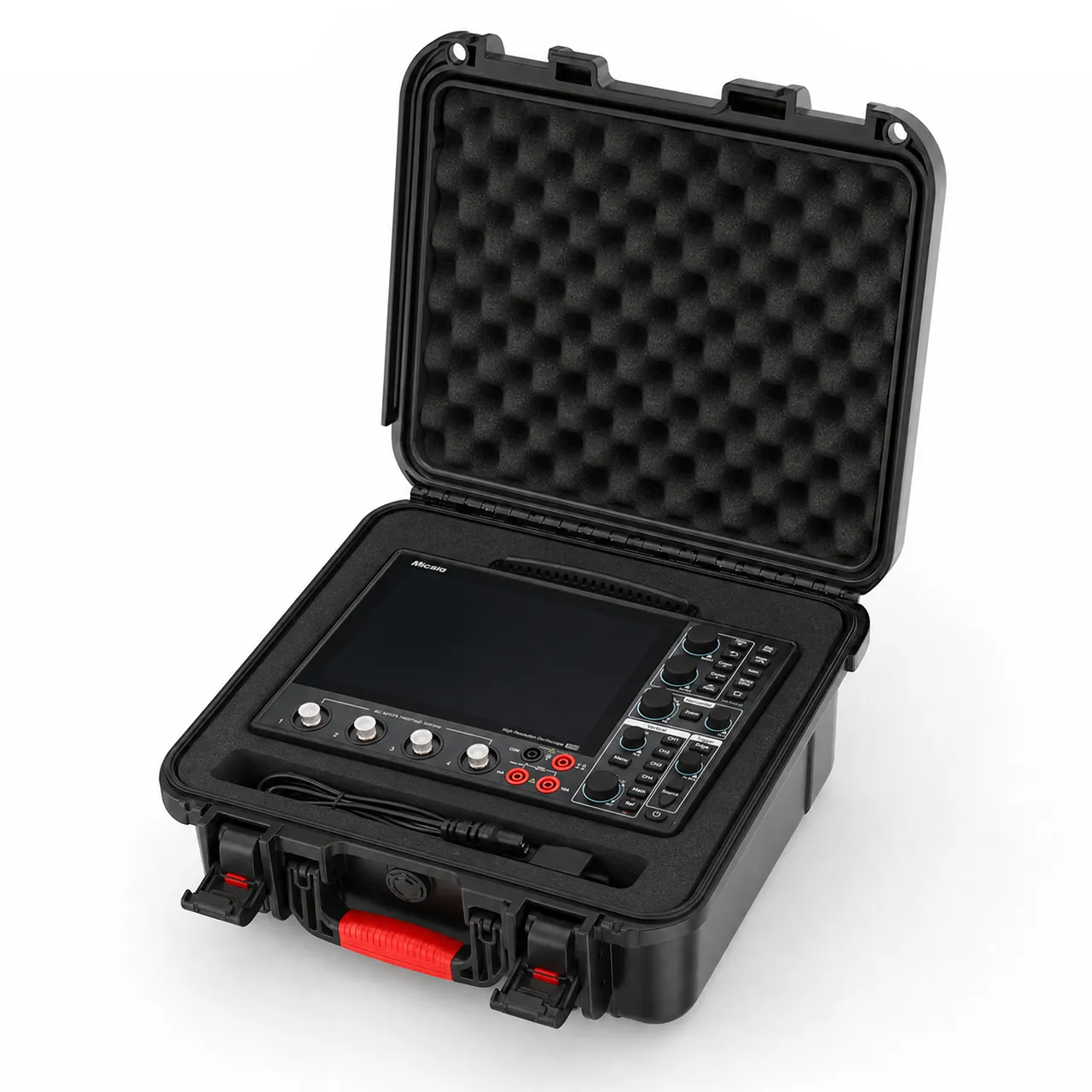
Case Load Verification and Stacking Limits
Load capacity should be verified against the real stacking condition rather than the strength of a single case.
Step one is to define the design load. If two cases stack on one pallet, the lower case carries the upper case self-weight plus a dynamic factor, which for road transport is reasonably taken as 1.5 to 1.8. The design load therefore reaches 2.5 to 3.6 times a single case weight.
Step two is to define the load path. Load must pass from the upper case base corners into the uprights or corner posts of the lower case, not into a liner working face. That requires continuous load-bearing structure at all four corners, with corner posts of stacked cases aligned.
Step three is to limit stacking. For liner and media cases above 600 kg gross, limit stacking to two high and print the maximum layer count together with a do-not-lay-on-side mark.
Step four is to assess side pressure. Side pressure in a media case rises linearly with fill height, so walls must be verified against the maximum fill. Where walls are plywood, add a stiffening rib every 400 to 500 mm of height.
Sea Freight: Balance, Lashing and Container Layout
Sea and rail transport constrain heavy spare parts cases more tightly than road, mainly in acceleration direction and lashing requirements.
Container layout principle: heavy items low, centred and laterally symmetrical. Liner and media cases are both high-density cargo, so place them on the container floor and as close as possible to the longitudinal floor bearers. Keep the left-right weight difference within 5 percent of total weight to avoid an additional torsional load when the vessel rolls.
Lashing requirements: sea lashing should resist roughly 0.4 g longitudinally and 0.5 g laterally for typical routes. Run lashings in a crossed pattern from the top of the case down to floor anchor points to form triangular restraint. Lashing angle strength must match the webbing, so the weld does not fail first.
Preventing bulk movement: fill gaps between cases and between cases and container walls with air bags or timber blocking, and fit dunnage or a door stop at the door end.
Moisture reinforcement: sea voyages are long with large temperature swings, so increase desiccant quantity and fit a humidity indicator card so moisture ingress can be judged quickly on arrival. Wooden packaging must meet ISPM 15. Where a case contains grease or hydraulic components, assess the applicable ADR or IMDG provisions, covered in the ADR/IMDG hazmat transport case requirements reference.
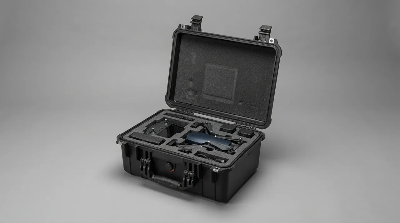
Arrival Inspection Checklist and Test References
Arrival inspection is the final test of the packaging design. Work through a checklist rather than relying on impression.
- Case exterior: no cracking, collapse or significant distortion, seals intact.
- Stacking and tilt indicators: tilt indicator not triggered, do-not-tip label intact.
- Humidity indication: indicator card within threshold, desiccant not saturated.
- Liner condition: no compression marks on working faces, no edge chipping, bolt holes not ovalised.
- Media condition: no spillage, no case bulging, no base deformation.
- Hardware kits: quantity matches the list, sealing rings not deformed.
- Documentation: material certificates, packing list and test report where specified.
On test references, assemble the set from the delivery scenario using the GB/T 4857 series, the ISTA series and ASTM D4169. GB/T 4857 covers vibration, impact, stacking and drop; ISTA procedures are selected by weight and transport mode; ASTM D4169 assigns test intensity across a distribution cycle. The three are not mutually exclusive. A common approach uses GB/T 4857 for base test items and ISTA or ASTM D4169 for unitised load verification, as described in the GB/T 4857 transport packaging test series reference.
Note that MIL-STD-810H is an environmental test method standard, cited only as a basis for environmental testing where such evaluation is required. It is not a product certification.
Batch Consistency and Custom Delivery Workflow
Concentrator spare parts are usually ordered once and delivered in several batches, which makes batch-to-batch consistency more important than single-unit performance. If liner tolerances work in the first batch and fail to load in the second, the site is left exposed.
Three levers control consistency. First, unify the machining datum: all batches reference the same digital model and the same base surface. Second, include key case dimensions such as internal length, width, height, corner post position and lifting point location in batch sampling. Third, retain first-article photographs and key dimension records for every batch.
Custom workflow typically follows these milestones:
- Provide liner drawings or samples, unit weight, centre of gravity, kit quantity per case and mill model.
- Receive case structure proposal, liner zoning drawing and gross weight estimate.
- Validate with a prototype case loaded with the actual part, under static stacking and short-haul transport.
- Run the agreed vibration, drop or incline impact tests and issue a report.
- Confirm assembly cycle time and operator ergonomics in a pilot batch.
- Deliver in batches and retain batch records.
The three most common mistakes are underestimating gross case weight, setting liner tolerances too tight, and overlooking the site lifting capability. All three are avoided by a single prototype validation.
For concentrator and grinding operators, JUNZHJIA covers the full chain from structural design to volume supply of spare-parts packaging, provides per-mill hardware kits and spare parts lists travelled with the case, and can take an ODM programme through to liners, markings and unpacking work instructions. If the mill already ships under an established packaging specification, an equivalent-replacement validation can be run against that baseline.
Frequently Asked Questions
Q: Can liners and grinding media share one case?
A: For short in-plant moves yes, for interprovincial road or sea freight no. The core conflict is how load is carried. A liner needs stable face support and released edges, while loose media flow under dynamic load and generate side pressure in the 15 to 20 kPa range, and that pressure acts directly on the liner, producing working face marks or edge chipping. If loading efficiency genuinely requires a mixed case, separate the two zones with a rigid divider, fully enclose and completely fill the media zone, restrain the liner zone independently, and keep the two base load paths separate. Splitting into separate cases is the safer option, and the space penalty can be recovered with optimised case dimensions and nested pallet design. From a cost standpoint, the extra case rarely costs as much as repairing a crushed liner on site, and for high-chromium liners a compression mark usually means scrapping the whole plate.
Q: What is the most reliable container for grinding media?
A: Choose by return cycles and delivery distance. Steel returnable bins offer the best stiffness and can be reused many times, suiting interprovincial and international freight, though they are heavy and costly to return empty. High-strength engineering plastic bins are lighter and corrosion resistant, suiting medium-distance and multi-cycle use, provided wall stiffness is confirmed against the side pressure from fill height. Flexible intermediate bulk containers suit sites with lifting capability; specify a safety factor of at least 5 to 1 and confirm that openings are sewn or tied to prevent media loss. Where the site wants to draw media in controlled quantities, use compartmentalised 25 kg or 50 kg bags inside a case. Whichever route is chosen, fill the container completely or divide the void into small compartments, so the charge cannot flow as one mass when the case tilts. Whichever system is chosen, verify container stiffness against the heaviest media grade expected, because high-chromium balls are noticeably denser than mild steel balls of the same diameter.
Q: Surface rust appeared on liners after sea freight. Is that a packaging failure?
A: Usually yes, but distinguish surface rust from deep corrosion. Manganese steel develops surface rust within days above 70 percent relative humidity, and that layer does not affect core properties and can be removed with a wire brush on site. Flaking corrosion or pitting, however, indicates that the barrier stage failed and should be investigated. There are three common causes: a torn or poorly sealed barrier film, insufficient or unevenly distributed desiccant, and condensation forming inside the case during transit. Fit a humidity indicator card and adequate desiccant sized from net volume and transit duration; for long sea voyages, 300 to 400 g per cubic metre is a reasonable upper figure. Where a customer requires zero rust tolerance, add an aluminium-laminate barrier outside the vapour-phase film and consider a pressure equalisation valve to relieve the differential pressure caused by temperature swings.
Q: Can different liner types be mixed in one case?
A: They can, provided the case is organised by mill chamber rather than by random stacking by size. Putting a complete liner set for one shell section into a single case lets the crew lay out the installation sequence directly on opening, which substantially reduces mis-installation and double handling. Three technical points need attention. First, different liner types have different thickness and stiffness, so restraint pockets must be machined separately rather than cut to one depth. Second, working face orientation must be consistent so faces never press against each other. Third, the centre of gravity shifts with the mix, so case load paths and lifting points must be recalculated for the actual combination. Curved end liners are best given their own profile cradle and should not be stacked with flat shell liners, because the curved surface concentrates load and deforms under compression.
Q: What is a sensible maximum weight per case?
A: Distinguish manual handling from mechanical handling. Where the site has a forklift or overhead crane only, a case can go up to 1 to 1.5 tonnes, provided forklift capacity, fork length and fork pocket positions all match. Where any manual secondary handling occurs, the individual package or compartment should stay under 25 kg, or under 50 kg for a two-person lift. The common practical solution is a two-tier structure: a large case for the main transport leg containing 25 kg unit bags or compartments, so the site can choose between lifting the whole case or drawing individual units according to available equipment. Bear in mind that as case weight approaches the site equipment limit, handling risk rises sharply. Retain at least 20 percent capacity margin, especially where the condition of site equipment is uncertain. Where a case is designed close to the lifting limit, specify the lifting gear in the packing documentation so the site does not improvise with undersized slings.
Q: Should I use rust preventive oil or vapour-phase film?
A: It depends on the surface condition and the following process step. Rust preventive oil suits liners with machined or fitted surfaces, such as a ground working face, because the film provides direct isolation, but it normally has to be wiped before installation, adding a step. On a plain cast surface, oil film adsorbs dust and forms an abrasive paste, so a vapour-phase film performs better. The advantage of vapour-phase film is that no wiping is needed, and the corrosion inhibiting atmosphere covers every metal surface in the case, including bolts and hardware, which suits kit packaging. A common practical combination is a thin rust preventive grease on machined surfaces, vapour-phase film on cast surfaces, desiccant inside the case and a barrier film outside. For deliveries beyond 90 days or with a sea leg, upgrade the vapour-phase film to heat-sealed vapour-phase bags and place the humidity indicator card where it can be read easily.
Q: What does wooden packaging need for export?
A: The main requirement is ISPM 15. International Standards for Phytosanitary Measures No. 15 requires wood packaging material used in international transport, including pallets, dunnage, support timber and wooden case components, to be heat treated or fumigated and marked with the IPPC symbol. The mark carries the country code, producer code and treatment code, where HT means heat treatment and MB means methyl bromide fumigation. Three errors are common. First, treating only the pallet while ignoring internal support timber. Second, using a blurred or incomplete mark that the destination customs authority rejects. Third, letting the fumigation validity lapse relative to the shipping date. In addition, paper documents, wooden accessories or plant-based filling materials inside the case can trigger quarantine requirements, so confirm with the freight forwarder in advance. Where a customer wants to eliminate wood-related risk entirely, switch to plywood or engineering plastic cases, which are generally not subject to ISPM 15.
Q: What should be inspected on arrival?
A: Work through seven items and keep records. First, case exterior condition, looking for cracks, collapse, significant distortion and intact seals. Second, stacking and tilt indicators, checking whether the tilt indicator triggered and the do-not-tip label is intact. Third, humidity indication, checking whether the indicator card exceeded its threshold and whether desiccant is saturated. Fourth, the liner itself, looking for compression marks on working faces, edge chipping and ovalised bolt holes. Fifth, media, checking for spillage, case bulging and base deformation. Sixth, hardware kits, confirming quantity against the list and checking sealing rings for deformation. Seventh, documents, verifying that material certificates and the packing list are complete. Photograph abnormalities during inspection, including a scale reference and the case number, so that traceability and responsibility allocation are supported later. Keep the completed checklist with the receiving record rather than filing it inside the case, so it remains available after the packaging has been discarded.
Q: How can the effect of wet material on packaging be reduced?
A: First separate two situations: the packaging becoming damp, and the contents arriving wet. If liners or media carry surface water or trapped moisture from the factory, any external seal simply locks the moisture in and accelerates corrosion. Confirm that surfaces are dry before packing, using dry compressed air or wiping where necessary. If the storage environment itself is wet, raise the barrier level of the packaging: heat-seal the barrier film, increase desiccant quantity, fit a humidity indicator card and add a moisture barrier pad under the base. For spares stored long term near a concentrator, an openable sealed case structure is preferable to one-time sealed packaging, so that periodic inspection and desiccant replacement remain possible. A three-month inspection interval works well, focusing on liner rust spots, liner moisture absorption and case distortion. Log each inspection with the date, ambient conditions and desiccant condition so that a trend becomes visible before a rust problem reaches the liner face.
Conclusion and Further Reading
The core of ball mill spare parts packaging is to handle two opposite cargo behaviours separately. Liners are attitude-sensitive and are solved with face support, released edges and profile restraint. Media are high-density bulk and are solved with rigid containers, full fill and side-pressure resistance. What the two share is the same heavy logistics logic: a known centre of gravity, a verifiable lifting point, a calculable stacking condition and an inspectable moisture barrier.
Proceed in four steps: classify by material and liner type, define the load path and liner zoning, verify with stacking and vibration testing, and then write the arrival inspection checklist into the purchasing contract annex. For combined cases above one tonne gross, adding one more case is usually better than leaving any single component's load condition uncertain.
JUNZHJIA serves concentrator and grinding operations with heavy-duty protective cases tailored to mill models, profile liners and complete hardware kit arrangements, with custom and joint development for concentrator and grinding projects, worldwide dispatch, and material and test documents provided on contract terms.
Further Reading