

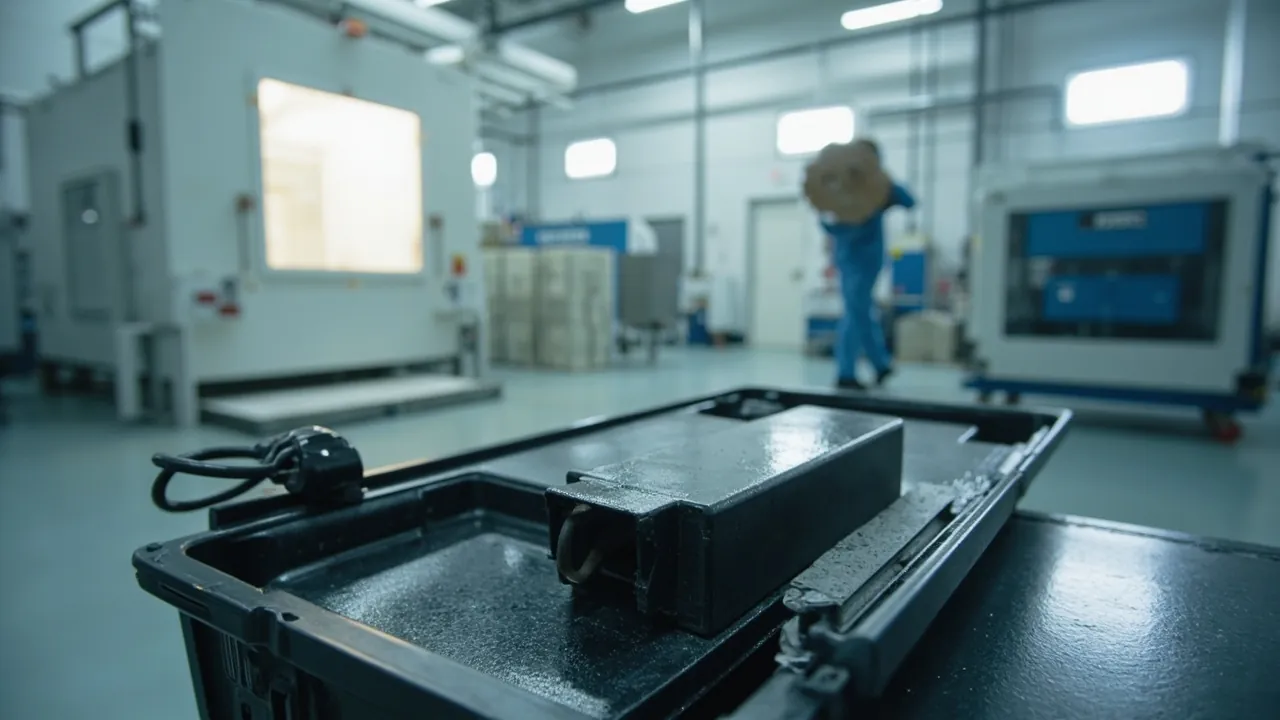
Surface finishing equipment cases face a group of risks that interfere with each other: spray mist, dust, abrasive media, coating residue and static electricity, all concentrated into one logistics chain. The headline conclusion is that the protection priority for coating and shot-blast components is not compressive strength but three things: precision flow passages that stay unblocked and undamaged, abrasive residue that does not migrate into other components, and a clearly defined containment boundary for coatings and chemicals. Spray guns and nozzles fear vibration, blockage and scoring. Impellers, blades and distributor wheels are hard, wear-resistant parts that fear chipping, impact and corrosion. Filter cartridges and dust-collection parts fear moisture and distortion. And once steel shot, blast dust or powder coating dust reaches other parts of the case, it simultaneously scratches, contaminates and creates conductive faults. Sealing to IP65 or better under IEC 60529 and GB/T 4208 answers whether outside dust and moisture can get in. What determines delivery quality is whether the liner cells are properly configured, whether abrasive media has been completely cleared, and whether the containment boundary for coating materials is written down.
This article is written for equipment engineers and buyers at surface treatment shops, coating lines, shot-blast equipment manufacturers and surface finishing consumable distributors. It works through spray guns and nozzles, coating pumps and lines, electrostatic guns and rotary atomizers, shot-blast assemblies, blast chamber liners, and dust collection and fan components item by item, and provides cell and liner material comparison tables, dust and coating residue handling procedures, a standards reference list, and acceptance and sampling steps that can be written straight into a procurement technical agreement. If you also manage global allocation of surface finishing consumables and spares, see the instrument case selection guide for a consistent baseline.
Table of Contents
- 1. Transport Risk Profile: Dust, Coatings and Precision Parts Stacked Together
- 2. Spray Guns and Nozzles: Vibration, Blockage and Scoring of Precision Passages
- 3. Coating Pumps and Lines: Draining and Separating Residual Coating
- 4. Electrostatic Guns and Rotary Atomizers: High-Voltage and ESD-Sensitive Parts
- 5. Shot-Blast Assemblies: Protecting the Wear Faces of Impellers, Blades and Distributor Wheels
- 6. Blast Chamber Liners and Wear Parts: Heavy Load, Brittleness and Stacking Limits
- 7. Steel Shot and Abrasive Residue: Dust Ingress and Cross-Contamination
- 8. Powder Coatings and Coating Containers: Containment Boundaries and Compliance
- 9. Dust Collection, Filtration and Fan Components: Cartridge Distortion and Motor Protection
- 10. Sealing, Pressure Equalization and Explosion-Risk Awareness
- 11. Liner and Cell Design: From EVA to CNC-Cut PE
- 12. Transport Verification and Standards Cross-Reference
- 13. Acceptance, AQL Sampling and OEM/ODM Collaboration
- Frequently Asked Questions
- Conclusion & Related Reading
1. Transport Risk Profile: Dust, Coatings and Precision Parts Stacked Together
Surface finishing shops share a distinctive property: equipment works continuously in spray mist, dust and abrasive spatter, and every spare part pulled from service carries a layer of fine dust that nobody notices. That dust is harmless in the shop. Once it enters a sealed case and migrates under vibration, it becomes a scoring source, a blockage source and a contamination source.
Six risk categories need separate treatment.
First, blockage and impact damage in precision passages. A spray gun's coating passage, air passage and nozzle orifice are typically in the 0.2 mm to 2 mm range. Dust or dried coating residue entering these passages causes flow deviation and poor atomization, while impact against a hard object deforms the orifice and changes the spray pattern and film thickness distribution directly.
Second, chipping of hard wear parts. Shot-blast impellers, blades, distributor wheels and liners are usually high-chromium cast iron or wear-resistant alloy with hardness above HRC 55. These materials are hard but brittle, and point loads or sharp-edge impact produce chipped corners and through-cracks. A chipped corner destroys dynamic balance, and the symptom after installation is sharply increased vibration.
Third, cross-contamination from abrasive and dust. Steel shot, blast dust and powder coating dust range from micrometers to millimeters. Once they leak from any component, they migrate freely inside the case, scoring precision surfaces, blocking passages and forming conductive paths in electrical components.
Fourth, coating and chemical residue. Residual coating, thinner and hardener inside guns, pumps, lines and coating containers are chemicals whose transport and storage carry compliance requirements. Residual liquid seeping inside a sealed case contaminates the liner, and some solvent vapors attack gaskets.
Fifth, special requirements for static and high-voltage parts. The high-voltage generator and electrode of an electrostatic gun fear moisture and electrostatic discharge damage, and control boards and signal cables are ESD-sensitive as well.
Sixth, moisture distortion in dust collection and filtration parts. Filter cartridges, bags and elements are porous structures. Absorbed moisture shrinks the media and distorts the pleat geometry, reducing filtration efficiency after installation, while compression causes permanent collapse.
Put these six together and the design direction for a surface finishing case becomes clear: cleanliness, individual cells and physical zoning first. For seal material selection in solvent vapor and dust environments, see protective case seal materials.
The table below gives reference protection parameters for common surface finishing parts and consumables.
| Component or material | Typical weight | Primary risk | Recommended liner | Buffer thickness | Notes |
|---|---|---|---|---|---|
| --- | --- | --- | --- | --- | --- |
| Electrostatic gun and nozzle | 0.5-5 kg | Passage blockage, nozzle impact, ESD | PE cut individual cell plus rigid sleeve | 10-20 mm | Clean nozzle and fit protective cap |
| Manual spray gun | 0.5-3 kg | Trigger mechanism distortion, passage contamination | PU foam individual cell | 10-15 mm | Restrain trigger |
| Coating pump | 5-80 kg | Residual coating seepage, piston distortion | EVA 40D plus dedicated liquid bay | 25-35 mm | Must be drained and capped |
| Coating line and hose | 1-20 kg | Residual curing, kinking and flattening | Coiled and restrained in a separate zone | 10-20 mm | Cap all ports |
| Rotary atomizer | 3-30 kg | High-speed bearing damage, bell cup distortion | Contoured PU liner plus individual cell | 20-30 mm | Pack the bell cup separately |
| Shot-blast impeller and distributor wheel | 5-60 kg | Chipped corners, through-cracks | PE cut cells plus rubber pads | 15-25 mm | Eliminate all point contact |
| Shot-blast blade | 0.5-5 kg | Corner chipping, set mismatch | Individual cell with set numbering | 10-15 mm | Pack by set, never mix |
| Blast chamber liner plate | 5-50 kg | Corner chipping, cracking under stacking | Timber skid, rubber pads, cells | 10-20 mm | Limit stack height |
| Filter cartridge and element | 2-30 kg | Moisture distortion, collapse | Individual cylindrical support plus barrier bag | No extra compression | Preserve roundness |
| Dust-collection fan and motor | 10-100 kg | Bearing damage, impeller distortion | EVA 40D plus rigid support | 25-35 mm | Pack impeller separately |
| Steel shot and abrasive media | 20-1000 kg | Leakage, abrasive contamination | Dedicated sealed container | Not applicable | Handle per material rules |
| Powder coating | 10-500 kg | Dust, moisture caking | Original packaging plus sealed zone | Not applicable | Mark per dangerous goods rules |
2. Spray Guns and Nozzles: Vibration, Blockage and Scoring of Precision Passages
Spray guns are the most precise items in a surface finishing case, and the components most often blamed when a coating line produces uneven results after installation.
First, cleaning must be completed before packing. The coating and air passages in a spray gun are typically 0.5 mm to 2 mm in diameter. If residual coating dries inside, it forms hard particles that are difficult to remove on site and readily score the passage walls. The recommended sequence is: dismantle the nozzle, needle and needle seat; flush with the specified solvent; blow dry with compressed air; confirm no residue; then pack.
Second, each nozzle needs individual protection. Nozzle orifices are typically in the 0.2 mm to 1.5 mm range, and their geometry directly determines atomization and spray pattern. Place each nozzle in its own PE cut cell with a protective cap, and never allow several nozzles to share one compartment. Hard nozzles in tungsten carbide or boron carbide are wear resistant but brittle and chip on impact, while soft plastic nozzles deform.
Third, needles and needle seats must not take load. A needle is a slender part whose straightness governs sealing and flow control. Support it in contoured PU foam or a dedicated rigid tube. The needle seat is a mating surface and needs a protective pad.
Fourth, restrain the trigger and adjustment mechanisms. Triggers and adjustment knobs are exposed moving parts, and compression in transit distorts them or changes their travel. Fill with foam so the trigger stays in the released position.
Fifth, zone the robot gun mounts and brackets separately. These are large parts with precision mating and rail surfaces that both dent and distort easily. Use PE cells with support along the full length rather than fixing only the two ends and letting the middle span sag. For the general rules on long-part support, see removable divider system design.
Sixth, treat electrostatic guns as ESD-sensitive parts. The high-voltage generator and electrode suit anti-static bags or anti-static liner material. See ESD shield case design.
3. Coating Pumps and Lines: Draining and Separating Residual Coating
Coating pumps, lines and containers are the main source of liquid residue, and they are the one category in a surface finishing case that absolutely requires physical zoning.
The four-step drain and clean procedure.
- Drain: close the inlet and outlet valves, open the discharge port and let coating in the pump chamber and lines flow out under gravity.
- Flush: circulate the specified solvent through the pump chamber and lines until the discharge runs clear.
- Purge: blow through with compressed air until no solvent mist exits.
- Cap: fit caps or protective covers on all inlets and outlets, and lock the pump shaft against rotation.
Why this matters. Residual coating seeps in transit and contaminates the liner and other components. Two-component coatings continue curing inside the case and can bond a piston to its cylinder. Solvent vapor accelerates gasket aging. None of these three consequences can be fixed with a wipe, which is why draining is not optional.
Build a dedicated liquid bay into the structure. Divide the case into a wet zone with replaceable absorbent pads and a dry zone separated by a solid partition, so that even a small seep stays local. For replaceable liners and zoning design, see custom foam insert solutions.
Coil and store lines and hoses. Coating hoses kink and flatten easily, and long-term small-radius coiling deforms the inner lining. Wind them onto a drum at least 15 times the hose outer diameter as a working ratio, cap both ends and avoid hard knots. If cured coating inside a hose cannot be removed, treat the hose as a consumable rather than returning it to service.
Mechanical protection for the pump body. Diaphragm, piston and gear pumps concentrate their weight in the body, and the transport risk is bending of the shaft or piston under lateral load. Support the body rigidly on EVA 40D or a cut PE liner with at least 80 percent contact, and leave the shaft in its retracted or locked position.
Containment boundary for coating containers. A coating container is a chemical container and should keep its original packaging, label and sealed lid, marked under the applicable rules. The protective case provides mechanical protection and contamination isolation; it is not used as chemical packaging or a chemical storage container.
4. Electrostatic Guns and Rotary Atomizers: High-Voltage and ESD-Sensitive Parts
Electrostatic guns and rotary atomizers are the highest value-density items in surface finishing equipment and among the easiest to damage by casual handling.
First, the atomizer bearing is the most fragile element. A rotary atomizer runs at 20,000 rpm to 60,000 rpm with extremely small bearing clearance. Impact in transit creates indentations on the bearing races, a condition known as false brinelling, which shows up after installation as excess vibration and noise and is often impossible to detect at assembly time. Support the atomizer body in contoured PU with at least 20 mm to 30 mm of buffer, and keep it out of cases shared with heavy items.
Second, the bell cup must be packed separately. The atomizing bell is a thin-wall precision part typically 30 mm to 100 mm in diameter, and compression takes it out of round. Remove and pack the bell separately in a rigid box with soft padding, never in the same compartment as other components.
Third, the high-voltage generator has strict moisture requirements. An electrostatic gun generator can output 60 kV to 100 kV. Moisture lowers insulation resistance, and on power-up it can cause tracking or abnormal discharge. Provide desiccant at the working ratio of 100 g of silica gel per 50 L of internal volume, adjusted for transit duration and climate zone.
Fourth, keep high-voltage and signal cables apart. A high-voltage cable damaged by small-radius bending develops internal insulation faults, and signal cables fear tension and static. Coil and restrain them separately and label their function on the outside of the packaging.
Fifth, electrodes and discharge pins are consumables. These are slender, sharp parts that fail on contact. Pack them individually as consumables and mark the package accordingly.
Sixth, settling time on arrival. Let units equilibrate at ambient temperature for 4 to 8 hours before power-up so they reach thermal balance with the room and avoid a condensation-driven short circuit. For sealing and moisture design, see waterproof case and IP rating implementation.
5. Shot-Blast Assemblies: Protecting the Wear Faces of Impellers, Blades and Distributor Wheels
The shot-blast wheel is the core assembly of a blast machine, and its impeller, blades, distributor wheel and control cage are hard wear parts whose protection logic is entirely different from precision parts: they do not fear softening from impact, they fear chipping, cracking and corrosion.
First, the failure mode of hard parts is brittle fracture. High-chromium cast iron and wear alloys reach HRC 55 and above but have low fracture toughness. Point loads, concentrated impact and sharp-edge strikes cause chipped corners, spalling and even through-cracks. Every point and line contact must therefore be eliminated in favor of area-contact support.
Second, blades must be packed by set and numbered. Blast blades are used as a set, and the blades in one set must match in weight and dimensions to preserve dynamic balance. Mixing sets causes out-of-balance vibration, accelerates bearing wear and sharply shortens bearing life. Give each blade its own cell, mark the set and position number beside it, and list the pairing on the packing list.
Third, the impeller and distributor wheel need a conforming support face. An impeller is a disc-shaped part, and an uneven support face concentrates weight on one or two points at the lower rim, which under sustained vibration promotes crack initiation. Use a PE cut cradle with a curved profile so contact is by area, and insert a 5 mm to 10 mm rubber pad between impeller and cradle.
Fourth, the control cage is a mating part and must not take load. Its clearance to the impeller determines the distribution of the blast pattern, and impact shifts that pattern and directly harms blast uniformity. Use an individual cell with a protective pad.
Fifth, corrosion protection cannot be skipped. Wear parts are hard, but their matrix can still rust, and loose scale after assembly becomes a contamination source. Wrap in VCI film with desiccant; the material grade can follow the approach in GB/T 4879 rust-preventive packaging.
Sixth, additional requirements when the whole assembly ships. If the customer wants the complete unit shipped, meaning motor, housing and impeller together, note three points: lock the axial position of the motor shaft; insert an elastic pad between housing and base; and put the tie-down points on reinforced areas of the base rather than on the thin housing wall. For latch and hinge load ratings on heavy cases, see toolbox hinge, latch and seal selection.
The table below compares protection orientation for blast components and wear parts.
| Component | Typical weight | Material orientation | Main failure mode | Recommended liner | Buffer or isolation |
|---|---|---|---|---|---|
| --- | --- | --- | --- | --- | --- |
| Blast impeller | 10-60 kg | High-chromium cast iron | Cracking, balance loss | PE curved area-contact cradle plus rubber pad | Area contact only, no point contact |
| Blast blade | 0.5-5 kg | High-chromium cast iron or alloy | Corner chipping, set mismatch | Individual cell with numbering | Pack by set, never mix |
| Distributor wheel | 3-20 kg | High-chromium cast iron | Chipping, corrosion | PU or PE individual cell plus VCI film | No shared cells with hardware |
| Control cage | 2-15 kg | High-chromium cast iron | Mating-face impact, pattern shift | PE cell plus protective pad | Soft pad on mating faces |
| Blast chamber liner | 5-50 kg | High-chromium iron or rubber | Corner chipping, cracking under stacking | Timber skid, rubber pads, cells | Limit stack height |
| Elevator bucket | 1-10 kg | Wear-resistant steel | Distortion, edge curling | Timber dividers | Prevent interlocking |
| Dust filter cartridge | 2-30 kg | Media plus cage | Moisture distortion, collapse | Cylindrical support plus barrier bag | No extra compression |
6. Blast Chamber Liners and Wear Parts: Heavy Load, Brittleness and Stacking Limits
Blast chamber liners, wear plates and guard plates are high-turnover items and a classic case of something that looks like steel plate but behaves like a brittle material.
First, stacking is the main cause of liner damage. High-chromium cast iron liners typically weigh 5 kg to 50 kg each with pronounced stress concentration at the corners. Stacked flat in several layers, the corners of the upper liner press on the face or edge of the lower one, contact stress far exceeds the allowable value, and cracks initiate at the edges. Use a combination of timber skid, rubber pads and PE cells: the skid carries the load, the rubber provides local elasticity, and the cells prevent horizontal movement.
Second, stack height must be limited. As a working practice, keep liner cases to two layers maximum with timber separators at least 15 mm thick between layers. If more layers are required, confirm middle-case deformation with a static stacking test rather than relying on judgment.
Third, protect edges and hole positions. If a liner mounting hole is deformed by compression, the bolt will not pass on site. Add protective pads around hole areas, or use a cut liner with reliefs at the hole positions.
Fourth, special requirements for rubber and composite liners. Rubber liners age and deform under load, so avoid direct sun and long-term heavy compression and store them in a separate zone. Composite liners of rubber bonded to steel plate need protection against peel forces at the bond line.
Fifth, cleaning is a precondition. Liners normally carry blast dust and steel shot fragments, which should be blown or brushed off before packing so that abrasive cannot migrate freely inside the case. This connects directly to the next section.
7. Steel Shot and Abrasive Residue: Dust Ingress and Cross-Contamination
Abrasive residue is the item in a surface finishing case that most needs proactive handling, because once it escapes inside the case it cannot be contained.
First, the cleaning procedure.
- Blow down the component in the work area first to remove surface dust and shot fragments.
- For parts with internal cavities, such as blast housings, distributor wheel clearances and elevator buckets, blow compressed air from inside outward.
- For dead corners, use a soft brush together with a vacuum.
- Confirm no visible abrasive remains before the part enters the packing area.
Second, abrasive must go into dedicated sealed containers. Steel shot, cut wire shot, blast dust and screen undersize must never be loose in the case. Once fine particulate migrates freely inside a case it causes three problems at once: it scores precision surfaces, blocks spray gun and nozzle passages, and forms conductive contamination in electrical components. Choose sealed containers appropriate to the material and label each with material name, particle size and weight.
Third, handle by material category. Blast dust and screen undersize are industrial solid waste and should be disposed of accordingly, while reclaimable steel shot should be kept separate from waste. The protective case is not used as a waste or hazardous waste container, which should be stated in the procurement agreement.
Fourth, express the cross-contamination boundary structurally. Divide the case into a clean zone and an abrasive zone with a solid partition between them, and secure containers in the abrasive zone against tipping under vibration. For liner and cell practice, see EVA foam insert custom process.
Fifth, humidity effects on abrasive. Some non-metallic abrasives cake when they absorb moisture and then blast less efficiently. Place a small amount of desiccant inside the abrasive container and a humidity indicator card inside the case so the condition can be judged on arrival. For sealing requirements, see the IP67 protective case design.

8. Powder Coatings and Coating Containers: Containment Boundaries and Compliance
Coatings, thinners and powder coatings are chemicals whose transport and storage are governed by dedicated rules. The point of this section is the boundary, not the performance.
First, a protective case is not chemical packaging. It provides mechanical protection, moisture control and contamination isolation, but it does not replace the original chemical packaging or the packaging, marking and declaration requirements that apply to dangerous goods. For cross-border movements, follow the classification, packing, marking and documentation rules in ADR/IMDG hazmat transport case requirements.
Second, coating containers should keep their original packaging and labels. If a container must be changed for transport, re-mark it under the applicable rules and keep the safety data sheet with the shipment. Do not pour loose coating or thinner into an unmarked container for transport.
Third, powder coating needs moisture and static control. Powder coating cakes when damp and then will not fluidize properly, and it is a combustible dust that presents a dust explosion risk at certain concentrations with an ignition source present. Keep the packaging sealed, moisture-proof and protected against static accumulation, and store it separately from ignition sources and oxidizers. The same applies in warehousing.
Fourth, isolate solvent-based coatings. Thinners and solvent-based coatings should be physically separated from other materials so that a leak does not contaminate other components, and where solvent vapor is present in a case it should not share a zone with parts that can produce sparks. Explosion-risk and static awareness can follow the thinking of the IEC 60079 series on explosive atmospheres, cited for awareness only and not as an explosion-proof certification.
Fifth, a leak response plan. Specify in the proposal that absorbent pads go under coating containers, containers get secondary restraint, replaceable absorbent pads are carried in the case, and the opening inspection sequence puts coating containers first. For cleaning and emergency handling, see how to clean a protective case.
Sixth, put the responsibility boundary in writing. State in the procurement agreement that the case is used for mechanical protection and contamination isolation of equipment and components, that it is not used as a hazardous chemical packaging container, and that compliant packaging, marking and declaration of chemicals inside the case is the responsibility of the commissioning party.
9. Dust Collection, Filtration and Fan Components: Cartridge Distortion and Motor Protection
Dust collection and filtration components sit alongside a surface finishing line, and their protection requirements differ from both precision parts and wear parts.
First, filter cartridges distort under compression. A cartridge is a cylindrical porous structure whose filtration performance depends on pleat geometry and roundness. Once compressed inside a case, especially laterally, the media collapses permanently, roundness is lost, and after installation filtration efficiency drops and cleaning becomes difficult. Fix each cartridge with an individual cylindrical support, add a support ring inside, avoid lateral compression, and wrap in a barrier bag to prevent moisture distortion.
Second, filter bags and cloth crease. A crease creates a local stress concentration and shortens service life. Store them flat or coiled in individual cells and never under load.
Third, pack the fan impeller separately. A dust collection fan impeller is a thin-wall part that goes out of round under compression. Remove and pack it separately on a contoured PU support; if removal is impossible, add internal support inside the fan housing to limit impeller movement.
Fourth, motor and bearing protection. Dust collection fan motors and blast wheel motors normally carry rolling bearings, and transport impact creates raceway indentations that appear as increased running vibration and noise. Support motors rigidly on EVA 40D or PU liner with at least 80 percent contact, fit a protective sleeve over the shaft extension, and eliminate hard points that connect directly to the motor.
Fifth, small control items such as pulse valves and solenoid valves. Use individual PE or PU cells, avoid compressing the coil, and cap the air ports.
Sixth, rotary valves and screw conveyors. These have rotating parts and close clearances. Lock the rotor or fit travel stops so it cannot rotate and wear in transit.
10. Sealing, Pressure Equalization and Explosion-Risk Awareness
Sealing, pressure equalization and explosion awareness are the three dimensions that distinguish a surface finishing case from an ordinary equipment case.
First, using IP ratings correctly. IEC 60529 and GB/T 4208 define a enclosure's protection against solid foreign objects and water. For this high-dust environment, IP65, meaning dust-tight and protected against water jets, is a reasonable starting point, and IP67, adding temporary immersion, suits sea freight, open yards and washdown cleaning. An IP rating promises nothing about impact resistance, stacking strength or corrosion performance. For dust specifically, the first digit, meaning dust-tight, often matters more than the water digit, because fine powder finds every opening.
Second, pressure equalization is a necessary companion to a sealed case. A sealed case experiences temperature and altitude changes in transit, and the differential repeatedly compresses the gasket. A watertight breather valve removes the differential while preserving the IP rating. For valve selection and placement, see pressure equalization valve design.
Third, explosion awareness must come early. Powder coating dust and some solvent vapors are combustible and present a risk at certain concentrations with an ignition source. This does not mean the case needs explosion-proof certification; it means the case should not combine combustible dust accumulation, static sparks and an enclosed space. Practical measures include sealed containment of dust-type materials, a case interior free of loose dust, anti-static liner material for electrical components, and avoiding opening the case in a dusty environment.
Fourth, the static conduction path. If powder coating and electronic control components share a case, separate the two with cells and anti-static materials so that a static discharge cannot affect both. See ESD shield case design.
Fifth, compatibility of case materials with solvents. Some solvents attack ordinary plastics and foams. State the chemicals expected inside the case in the agreement and have the supplier confirm material compatibility.
11. Liner and Cell Design: From EVA to CNC-Cut PE
The liner in a surface finishing case is normally a combination of three materials serving three functions: structural bearing, elastic energy absorption and cut-part locating.
| Material | Typical density or hardness | Cushioning | Oil and solvent orientation | Main applications | Cost orientation |
|---|---|---|---|---|---|
| --- | --- | --- | --- | --- | --- |
| EVA | 30D-70D | Moderate, good recovery | Fair; assess for long solvent contact | Coating pumps, motors, medium parts | Medium |
| PE cut foam | 25-45 kg/m3 | Low, primarily locating | Good | Nozzles, blades, slender-part cells | Medium to high (CNC dependent) |
| PU foam | 20-35 kg/m3 | High, good absorption | Fair | Atomizers, needles, cartridge ends | Medium |
| EPP | 30-60 g/L | High, multi-impact recovery | Good | Base of heavy parts, pallets | Medium to high |
| Rubber pad (NBR or EPDM) | 60-80 Shore A | Local elasticity | Excellent, NBR is oil resistant | Contact faces with wear parts | Low |
| Timber skid and plywood | Structural | No cushioning | Excellent | Load base, liner plate bearing | Low |
| Foil-laminate moisture film | Film | No cushioning | Fair | Filter media, powder moisture barrier | Low |
| Anti-static foam | 25-40 kg/m3 | Moderate | Fair | Control boards, electrostatic guns | Higher |
Three principles for cell design.
First, zone by cleanliness rather than by weight. The key zoning dimension for surface finishing spares is cleanliness: nozzles, needles and atomizers belong in an absolute clean zone; coating pumps and lines belong in a wet zone; impellers and liners belong in a wear-part zone; steel shot and abrasive belong in an abrasive zone. The four zones must be separated by solid partitions, not by the soft boundary of foam.
Second, group items of similar magnitude together. Group by weight and by vibration sensitivity. Put a 0.5 kg nozzle in the same compartment as a 30 kg impeller and, however good the liner, the nozzle becomes the first item to fail.
Third, prioritize replaceability. Surface finishing spares turn over frequently and cases are reused for years. Make the locating layer that wears fastest a replaceable component, such as a shallow tray or an insert plate, to extend case life. For quantitative material comparison, see case foam material comparison.
12. Transport Verification and Standards Cross-Reference
The ISTA series. ISTA Series 1 covers basic performance tests, Series 2 partial simulation and Series 3 general simulation. For surface finishing equipment cases, 2A for individual packages up to 68 kg and 3E for unitized loads over 68 kg moving as LTL freight are most often cited. For selection logic and sequences, see the ISTA transport testing procedure.
The GB/T 4857 series. This series specifies basic test methods for transport packages, including drop, stacking, vibration, impact and water spray. Citing it in domestic contracts is easier for third-party laboratories to execute. See GB/T 4857 transport packaging in practice.
ASTM D4169. This standard is organized around a distribution cycle and combines sequences through a DC number, allowing severity to be tailored to the real logistics chain. See ASTM D4169 distribution cycle testing.
MIL-STD-810H. This standard provides environmental test methods for vibration, shock, temperature and humidity, low pressure, and sand and dust. State clearly that citing it means only that its methods are used as a basis for environmental verification; it does not constitute military certification or a military qualification. See MIL-STD-810H environmental test basis. Its sand and dust test methods are directly relevant to equipment cases in high-dust environments.
A recommended test combination. For surface finishing equipment cases, use four legs: vibration, drop or shock, stacking, and temperature-humidity cycling. Add two targeted verifications on top. First, dust ingress verification: place clean test papers and sample coupons in the clean zone, then check after the vibration test whether abrasive or dust reached the clean zone. Second, cleanliness verification: wipe the clean zone surfaces with a lint-free cloth after opening and check for visible residue. These two verifications reflect real delivery quality far better than an appearance check alone.
13. Acceptance, AQL Sampling and OEM/ODM Collaboration
Design confirmation stage:
- Confirm the parts list, unit weights, envelope dimensions and cleanliness class requirements.
- Confirm the four-zone plan, namely clean zone, wet zone, wear-part zone and abrasive zone, with solid partition details.
- Confirm the replaceability of the liquid bay and absorbent pads.
- Confirm the basis for the desiccant calculation and the number of humidity indicator cards.
- Confirm case IP rating, pressure equalization valve configuration and material compatibility.
Sample verification stage:
- Check fit tolerances and the feel of insertion and removal for nozzles, needles and atomizers.
- Check that impeller, blade and liner contact is by area, not by point or line.
- Complete the two targeted verifications for dust ingress and cleanliness.
- Run the agreed loaded vibration, drop and stacking sequence.
Volume delivery stage:
- Build the AQL plan following the sampling logic of GB/T 2828.1. Critical defects such as seal failure, dust ingress into the clean zone, support fracture and chemical container leakage should be set at AQL 0. Major defects such as nozzle passage contamination, impeller corner chipping, liner cracking and out-of-tolerance liner cells generally fall between AQL 0.65 and 1.5. Minor defects such as cosmetic scratches and print misregistration generally fall between AQL 2.5 and 4.0. See custom case acceptance and AQL sampling.
- Randomly open cases each batch to check clean-zone residue and fastener torque.
- Verify handling symbols under GB/T 191, dangerous goods markings and accompanying documents.
OEM/ODM and volume supply collaboration. Surface finishing equipment manufacturers and consumable distributors typically need liners matched to equipment models, cells sized to consumable formats, markings under their own brand, and staged delivery against an annual framework. JUNZHJIA (Kexin New Materials (Guangdong) Co., Ltd.) provides CNC-cut liners to component drawings, matched seals and pressure equalization valves by model, and inspection documents covering IP rating and whole-case testing, and it accepts OEM/ODM and wholesale agency business. For customers shipping coatings and abrasives together, an integrated four-zone plus liquid-bay arrangement is available. For factory assessment and sampling workflow, see how to choose a protective case OEM factory.
Frequently Asked Questions
Q: Does a surface finishing equipment case have to reach IP67, and is IP65 enough in a dusty environment?
A: In a high-dust environment the dust digit of the IP rating matters more than the water digit. Under the naming rules of IEC 60529 and GB/T 4208, the first digit indicates protection against solid foreign objects and the second indicates protection against water. A first digit of 6 means dust-tight with no dust ingress, while 5 means dust-protected, allowing limited ingress that does not interfere with function. For components such as spray guns, nozzles and blast parts that fear dust ingress, IP65 and IP67 are therefore equivalent on dust: both are dust-tight. The difference is water: IP65 is protected against water jets, and IP67 adds temporary immersion, typically tested at 1 m for 30 minutes. Three questions settle the choice: is there any risk of open storage or short-term standing water; does the route include sea freight with its humidity and condensation cycles; and will the case be washed after arrival? If any one is true, IP67 is the better fit; if all legs are covered road transport, IP65 is sufficient. Three cautions apply. An IP rating promises nothing about impact, stacking or corrosion. A sealed case must have a pressure equalization valve, otherwise the differential from temperature and altitude changes repeatedly compresses the gasket. And for dust specifically, the more effective measures sit on top of the rating: liner cells, a solid clean-zone partition, and a dust ingress verification test, because dust usually enters through operating steps outside the sealing structure rather than through the gasket itself.
Q: What is the biggest transport risk for spray guns and nozzles, and how should they be packed?
A: The biggest risk is contamination of precision passages and loss of nozzle geometry, not visible impact damage. A spray gun's coating and air passages are typically 0.5 mm to 2 mm in diameter, and nozzle orifices are in the 0.2 mm to 1.5 mm range, with geometry that directly determines atomization and spray pattern. Residual coating drying inside a passage forms hard particles that are hard to remove on site and readily score the passage walls, while impact against a hard object deforms the orifice and changes both the spray pattern and the film thickness distribution. Pack in five steps. First, dismantle nozzle, needle and needle seat, flush the passages with the specified solvent, blow dry with compressed air and confirm no residue before packing. Second, place each nozzle in its own PE cut cell with a protective cap, never several nozzles in one compartment; hard nozzles in tungsten carbide or boron carbide are wear resistant but chip on impact, while soft plastic nozzles deform. Third, support needles, which are slender parts whose straightness governs sealing and flow control, in contoured PU foam or a dedicated rigid tube. Fourth, fill with foam to restrain the trigger and adjustment knobs so the trigger stays in the released position. Fifth, treat the electrostatic gun generator and electrode as ESD-sensitive, use anti-static bags or liner, and provide desiccant at the working ratio of 100 g of silica gel per 50 L of internal volume. Let equipment equilibrate 4 to 8 hours before power-up.
Q: Why can ordinary foam packaging not be used for shot-blast impellers and blades?
A: Because their failure mode is brittle fracture, and ordinary foam packaging tends to create exactly the point contacts and concentrated loads that cause it. Shot-blast impellers, blades, distributor wheels and liners are normally high-chromium cast iron or wear alloy with hardness above HRC 55 but low fracture toughness. Point loads, concentrated impact and sharp-edge strikes produce chipped corners, spalling and even through-cracks, and a chipped corner destroys dynamic balance so that vibration rises and bearing life falls sharply after installation. The problem with ordinary foam is that it crushes under a heavy part, and once crushed, contact changes from area contact to point contact, concentrating load on a few locations instead of spreading it. Three measures follow. First, provide area-contact support with a CNC-cut PE liner or curved cradle, eliminating point and line contact completely. Second, insert a 5 mm to 10 mm rubber pad at 60 to 80 Shore A between wear part and support face, which provides local elasticity and keeps metal from pressing directly on hard liner material. Third, pack blades by set with numbering, because blades in one set must match in weight and dimensions to preserve dynamic balance, and mixing sets causes out-of-balance vibration. Wear parts can also rust at the matrix, and loose scale becomes a contamination source, so wrap in VCI film with desiccant at a grade determined using the approach in GB/T 4879.
Q: How should steel shot and blast dust residue be handled, and can the case serve as a waste container?
A: Abrasive residue must be completely cleared before packing, because once it escapes inside the case it can no longer be contained. Clean in four steps: blow down the component in the work area first to remove surface dust and shot fragments; for parts with internal cavities such as blast housings, distributor wheel clearances and elevator buckets, blow compressed air from inside outward; for dead corners use a soft brush with a vacuum; and confirm no visible abrasive before the part enters the packing area. The removed abrasive must go into dedicated sealed containers, and steel shot, cut wire shot, blast dust and screen undersize must never be loose in the case. Fine particulate migrating freely inside a case causes three problems at once: it scores precision surfaces, it blocks spray gun and nozzle passages, and it forms conductive contamination in electrical components. Handle by material category as well: blast dust and screen undersize are industrial solid waste and should be disposed of accordingly, while reclaimable steel shot should be kept separate from waste. On the role of the case, be explicit: a protective case provides mechanical protection and contamination isolation and is not used as a solid waste or hazardous waste container, which should be written into the procurement agreement. Structurally, divide the case into a clean zone and an abrasive zone with a solid partition, secure abrasive containers against tipping, and add a small amount of desiccant inside each container to prevent moisture caking.
Q: Can powder coatings and solvent-based coatings be shipped in the same case as equipment?
A: They can share a case, but only if three boundary conditions are met; otherwise ship them separately. The first boundary is packaging. A protective case provides mechanical protection and contamination isolation and does not replace the original chemical packaging or the packaging, marking and declaration requirements that apply to dangerous goods; for cross-border movements, follow the classification, packing, marking and documentation rules of the ADR and IMDG frameworks. Coating containers should keep their original packaging and labels; if a container must be changed for transport, re-mark it under the applicable rules and keep the safety data sheet with the shipment. Do not pour loose coating into an unmarked container for transport. The second boundary is physical separation. Keep solvent-based coatings physically apart from other materials so a leak does not contaminate other components, put absorbent pads under containers and apply secondary restraint, and where solvent vapor is present avoid sharing a zone with parts that can produce sparks; explosion-risk and static awareness can follow the thinking of the IEC 60079 series on explosive atmospheres, cited for awareness only. The third boundary concerns material properties. Powder coating cakes when damp and is a combustible dust with a dust explosion risk at certain concentrations with an ignition source, so packaging should stay sealed, moisture-proof and protected against static accumulation, and stored apart from ignition sources and oxidizers. State in the agreement that the case is not a hazardous chemical packaging container.
Q: How should filter cartridges and dust collection fans be packed, and what details are easily missed?
A: Their requirements sit between precision parts and wear parts, and the easily missed details cluster around two words: distortion and bearings. A filter cartridge is a cylindrical porous structure whose performance depends on pleat geometry and roundness. Once compressed inside a case, especially laterally, the media collapses permanently and roundness is lost, which appears after installation as reduced efficiency and difficult cleaning. Fix each cartridge with an individual cylindrical support, add a support ring inside, avoid lateral compression, and wrap in a barrier bag against moisture. Filter bags and cloth are a different case: they fear creases, which create local stress concentrations, so store them flat or coiled in individual cells and never under load. A dust collection fan impeller is a thin-wall part that goes out of round under compression, so remove and pack it separately on contoured PU support; if removal is impossible, add internal support inside the housing to limit impeller movement. Most easily missed are the motor and bearings. Dust collection fan motors and blast wheel motors normally carry rolling bearings, and transport impact leaves indentations on the races that show up as increased running vibration and noise, a defect that is often undetectable at assembly time. Support motors rigidly on EVA 40D or PU with at least 80 percent contact, fit a protective sleeve on the shaft extension, and eliminate hard points touching the motor directly. Give pulse and solenoid valves their own cells, avoid compressing the coil, and cap the air ports.
Q: How can a surface finishing equipment case be verified so that dust does not reach the clean zone?
A: Add two targeted verifications on top of the usual vibration, drop and stacking tests, because dust ingress is the most insidious failure mode for this case class. The first is dust ingress verification. Place clean test papers and sample coupons in the clean zone, place a small quantity of steel shot or blast dust with a particle size close to the real material in the abrasive zone, run the agreed vibration sequence, then open the case and check the papers and coupons for visible particles. If particles are found, record position and quantity as the basis for improving the sealing and zoning design. The second is cleanliness verification. After opening, wipe the clean zone surfaces with a lint-free cloth, focusing on nozzle cells, needle cells and electrical component cells, and check for visible residue and oil film. These two verifications reflect real delivery quality better than an appearance check, because they simulate the real path by which abrasive leaks somewhere and migrates under vibration. One caution: dust usually enters through steps outside the sealing structure, such as opening the case in a dusty environment, soft boundaries between liner cells that cannot stop fine powder, or abrasive containers that tip because they were not given secondary restraint. Confirm three work requirements alongside the tests: packing is done in a clean area; the four zones are separated by solid partitions rather than soft boundaries; and abrasive and dust containers are individually sealed and secondarily restrained. Combine all five into one acceptance checklist.
Q: What drives the cost and lead time of a custom liner, and is small-batch production realistic?
A: Four cost elements dominate. First, programming and tooling: a CNC-cut liner needs toolpath design from component models, and the more complex the shapes and the more cells required, the longer the programming and setup time; volume exists to spread this fixed cost. Second, material: EVA, PE, PU, EPP and anti-static foam differ noticeably in unit price, and switching a single case from 45D EVA to 30 kg/m3 PE can change material cost by tens of percent, while oil resistance or anti-static requirements push unit prices higher again. Third, machining time: cut depth, profiled channels, curved cradles and multi-layer structures differ widely in cycle time, and items needing curved area-contact cradles such as blast impellers are especially time consuming. Fourth, verification: if the buyer requires loaded vibration, drop and stacking tests on the whole case, or dust ingress and cleanliness verification, that cost must be counted separately. On lead time, the determining factors are the number of programming and first-article iterations, material procurement cycles and verification scheduling rather than production speed alone; treat first-article approval as an independent milestone so that later rework is avoided. Small batches are entirely workable. The usual route is a single sample to confirm fit tolerances and the feel of insertion and removal, followed by staged production against an annual framework. For customers running many models on one line, a common support base plus model-specific shallow trays concentrates customization cost in a replaceable tray layer. JUNZHJIA provides liner samples and fit verification from drawings.
Q: How should a batch of surface finishing equipment cases be accepted, and how should AQL sampling be set up?
A: Accept in three stages and set decision rules following the sampling logic of GB/T 2828.1. Stage one is arrival inspection and document check: verify handling symbols, dangerous goods markings, packing list and component numbers against each other; inspect for through-cracks, distortion and detached gaskets; and after opening, check the seal condition and leak traces on coating containers first, then look for dusting, oil contamination and crushed liner. Order matters here, because liquid leakage can mask other damage. Stage two is functional checking: spot-check that pressure equalization valves breathe freely; sample hinge and latch operating force and end stops; check nozzle cells and electrical component cells for dust residue; read the humidity indicator cards; and check whether abrasive containers have tipped or ruptured. Stage three is test verification: run the agreed loaded vibration, drop and stacking sequence, and add the two targeted verifications for dust ingress and cleanliness. For the AQL plan, classify defects into three groups. Critical defects such as seal failure, dust ingress into the clean zone, support fracture and chemical container leakage should be set at AQL 0. Major defects such as nozzle passage contamination, impeller corner chipping, liner cracking, out-of-tolerance liner cells and latch failure generally fall between AQL 0.65 and 1.5. Minor defects such as cosmetic scratches, print misregistration and slightly unclear marking generally fall between AQL 2.5 and 4.0. Determine sample size from lot size at general inspection level II, and keep opening photographs and test records as the basis for traceability.
Conclusion & Related Reading
The design logic of a surface finishing equipment case compresses into three steps in a fixed order: clean first, zone second, seal third. Cleaning determines whether abrasive and coating residue becomes a scoring and blocking source. Zoning determines whether clean parts, wet parts, wear parts and abrasive can avoid interfering with each other. Sealing determines whether outside dust and moisture stay outside. The order cannot be reversed, because sealing a dirty case only locks the contamination in. Zone by cleanliness rather than by weight, separate with solid partitions rather than soft boundaries, support on area contact rather than point contact, and turn the result into data with dust ingress and cleanliness verification, and delivery quality moves from a matter of luck to a matter of records.
For buyers, the four items most worth writing into the technical agreement are the four-zone plan and partition format, the contact method for clean and wear parts, the sealing and restraint method for abrasive and coating containers, and the acceptance criteria for dust ingress verification. For surface finishing equipment manufacturers and consumable distributors, standardizing liners by equipment model and making the wear-prone locating layer replaceable is the most direct way to reduce global spare-parts allocation cost. JUNZHJIA provides liners cut to drawings, matched seals and pressure equalization valves by model, and inspection documents covering IP rating and whole-case testing, and it accepts OEM/ODM and wholesale agency collaboration. Bring your component list and logistics route and we can work through the specification together.
Related Reading