

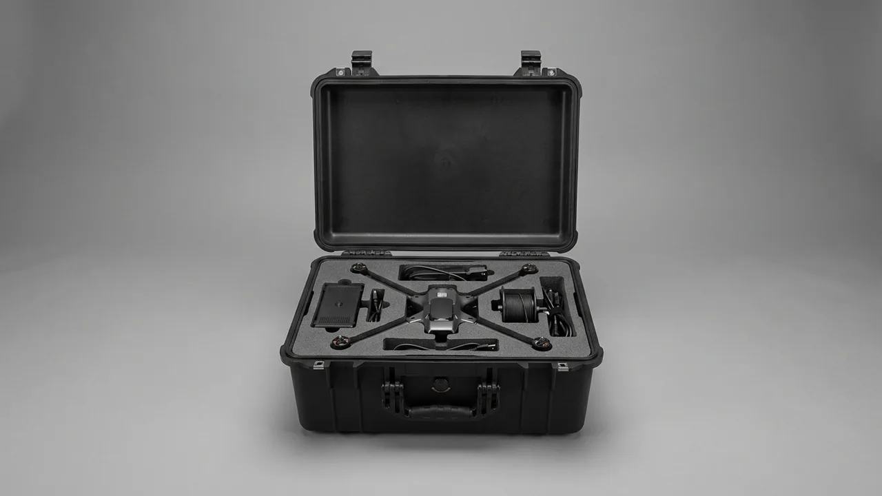
A brazing furnace case has to protect a family of parts that are brittle, thin-walled, moisture-sensitive and vibration-sensitive at the same time. Ceramic fiber chamber liners and lightweight insulating bricks can barely tolerate point loading. Heat-resistant alloy retorts (muffles) and radiant tubes commonly run 2 to 6 mm in wall thickness and deform easily. Molybdenum disilicide (MoSi2) and silicon carbide (SiC) heating elements are brittle at room temperature and break from a single impact, while thermocouples, compensating cables, vacuum flange knife edges and O-ring grooves belong to the micron-precision class. The core conclusion is that a brazing furnace case must be compartmentalized under four separate logics: independent moisture-proof cradling for chamber liner modules, curved anti-deformation support for retorts and radiant tubes, segregated anti-fracture cells for heating elements, and precision anti-vibration cells for instrumentation and seals. The delivery file must also carry the post-arrival bake-out curve and element pre-oxidation requirement. A generic crate with one generic foam insert will almost certainly end in a deformed retort, a moisture-shattered liner or a broken heating element.
The parts turnaround environment of a brazing furnace concentrates its contradictions. On new-build or relocation projects, liner modules often travel over a thousand kilometres by road from the furnace builder to the site, and self-compression plus edge chipping of ceramic fiber modules under vibration opens gaps in the furnace wall. At 1100 C those gaps become local hot spots and a glowing shell. A thin-wall retort weighing several hundred kilograms, if left unsupported at mid-span between the storage yard and the furnace, can arrive with enough out-of-roundness that it will not enter the shell or will touch the heating elements. A single MoSi2 element broken in transit can mean a month of import lead time, and the break usually starts from a 5 mm hard spot left in the liner. A vacuum flange knife edge nicked into a burr keeps leak rate above target, and the site will blame the pump set rather than the case. Worse, most of this damage is invisible at the moment of unpacking: hidden moisture in a liner only reveals itself as spalling during the first bake-out. This article gives executable packing parameters, insert compartment plans, dew-point and bake-out targets, and acceptance criteria organized by brazing furnace part family, for use by heat-treatment plant equipment departments, furnace builders and spare-part stores when selecting, accepting and transferring parts.
Table of Contents
- Transport Environment and Case-Selection Boundary
- Chamber Refractory and Liner Module Anti-Impact and Anti-Moisture
- Thin-Wall Anti-Deformation for Retorts and Radiant Tubes
- Anti-Fracture and Anti-Moisture-Absorption for Heating Elements
- Anti-Vibration for Thermocouples, Compensating Cables and Control Components
- Vacuum Sealing Faces, O-Rings and Flange Knife Edges
- Door, Viewport and Seal-Groove Closing Accuracy
- Protection of Vacuum Pumping Sets and Valves
- Atmosphere System Parts and Hydrogen Line Safety
- Heavy Furnace Body Parts: Lifting and Saddle Design
- Insert Compartmentalization, Humidity and Dew-Point Control
- Post-Arrival Bake-Out Curve and Heating Requirements
- Labeling, Inspection, Unpacking Acceptance and Test Basis
- FAQ
- Conclusion and Related Reading
Transport Environment and Case-Selection Boundary
Drawing a clear line between what goes into a case and what does not is the step where brazing furnace projects most often go wrong. A complete furnace shell, an already bricked furnace body assembly, and water jackets or transformer cabinets rigidly connected to the body all exceed the load and lift capacity of a standard protective case. They move on dedicated steel frames with multi-point lashing in the plant, and forcing them into a case drags both the lashing system and the case into risk. What genuinely needs a dedicated case is seven part families: ceramic fiber modules, lightweight insulating bricks and castable preformed blocks; retorts (muffles), radiant tubes and heat-resistant alloy inner cylinders; resistance ribbon, resistance wire, heating tubes and SiC or MoSi2 rod elements; thermocouples, sheathed temperature sensors and compensating cables; vacuum flanges, O-rings, metal gaskets and valves; doors, viewports and seal-groove assemblies; and complete sets of fasteners, ceramic insulators and support bricks. What these seven families share is that their value concentrates in surface condition or geometric accuracy, they must be managed as a set, and any single out-of-tolerance part drags down the temperature uniformity of the whole furnace.
Case-selection principles compress into three rules. The first is to compartmentalize by damage mechanism rather than by size: moisture-sensitive liners, bend-sensitive thin-wall cylinders and vibration-sensitive instrumentation have mutually incompatible protection logics, and forcing them into one cell means the whole cell can only achieve the lowest of the three grades. The second is to isolate by material and cleanliness: carbon steel frames, stainless parts, ceramic parts and graphite parts mixed together means carbon steel rust scale contaminates the vacuum chamber and graphite, while graphite dust contaminates ceramic insulator surfaces and becomes a creepage path. The third is to set the moisture protection grade by storage period and bake-out requirement rather than by transit days: weeks often separate shipment from bricking and bricking from first heat-up, and if that window crosses a rainy season or an ocean leg, the case must carry active moisture control with a humidity indicator card, not a single layer of ordinary plastic film. Violating any of the three costs far more to recover than a new case.
| Part Family | Primary Damage Mode | Key Protection Requirement |
|---|---|---|
| --- | --- | --- |
| Ceramic fiber modules and lightweight brick | Edge chipping, moisture uptake, compression | Independent moisture-proof cell, limited point load, no direct hard contact |
| Retorts, muffles and radiant tubes | Ovality distortion, wall dents, weld cracking | Curved saddles at multiple points, axial location, no single-point suspension |
| Resistance ribbon, wire and heating tubes | Breakage, shattered insulators, bent terminals | Single-piece location, elastic cushioning, no stacking or tight lashing |
| SiC and MoSi2 rod elements | Room-temperature brittle fracture, moisture pesting | Vertical or large-radius support, dry cell, humidity record |
| Thermocouples and compensating cables | Accuracy drift, shattered ceramic sleeves | Anti-vibration liner, separate sleeve cells, coiled to minimum bend radius |
| Vacuum flanges and O-rings | Knife-edge burrs, seal-face scratches, elastomer ageing | Knife-edge guard rings, seal-face film, elastomer kept from light and heat |
| Doors and viewports | Closing-face damage, glass cracking | Closing-face film, vertical glass fixing, no flat stacking |
Chamber Refractory and Liner Module Anti-Impact and Anti-Moisture
Modern brazing furnace chambers are lined mainly with ceramic fiber modules, lightweight insulating bricks and castable preformed blocks. Their insulating performance comes from high porosity, and high porosity simultaneously means low strength and strong moisture uptake. Ceramic fiber modules commonly run between 128 and 220 kg/m3 in bulk density (typical values), and edge compressive strength is low enough that the self-weight of stacked modules can chip the bottom layer. Lightweight brick often exceeds 60 percent apparent porosity and can absorb measurable water within days at 80 percent relative humidity. Neither defect shows up at outgoing inspection; both surface during the first heat-up.
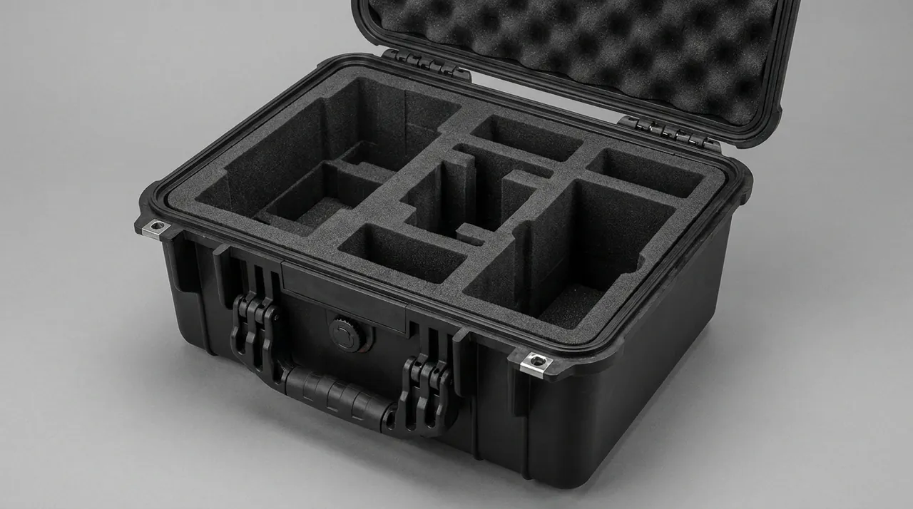
A moist liner fails along two paths during bake-out. The first is spalling: free water inside the pores flashes to steam near 100 C, and when vapour pressure exceeds the body strength the surface layer peels away, leaving a spall crater. The wall is thinner there, becomes a hot spot in service, and in the long run can glow the shell. The second is permanent loss of insulation performance: once fiber is compressed, the fiber collapses and does not fully recover, so the joint density after bricking is low, heat short-circuits out through the joints, shell temperature rises and energy consumption follows. The packing objective for liner modules is therefore not to hold them tight but to apply no compression, no moisture and no abrasion.
Five executable measures follow. First, modules should not be stacked directly on one another. Each goes into its own moisture-proof cell, or all modules sit in a single layer on a carrying tray with a continuous divider between layers, and the divider itself must be stiff enough not to sag locally. Second, only surface contact is permitted with a module. Any point or line contact is a direct cause of chipping, which rules out tag nails, lashing buckles and hard insert claws; tags should be moved to the outside of the cell. Third, the whole case should use active moisture control: low-absorption liner treatment, low-shedding desiccant inside the cell, and humidity indicator cards. At least two card positions per case are recommended so the condition can be judged without opening the case. Fourth, for ocean freight or long storage, the purchase specification should state a moisture content and absorption test method for the liner material itself, and the supplier should provide the water absorption data of the insert material rather than only appearance and dimensions. Fifth, if the site finds the proportion of chipped module edges above the agreed limit during bricking, the module should be replaced rather than patched with castable, because the patch has a different thermal expansion behaviour from the fiber module and becomes a new crack origin under thermal cycling.
When JUNZHIJIA customizes inserts for brazing furnace liner parts, the module cells are normally built as independent tray compartments with a low-absorption liner face, a grab clearance between compartments for manual handling, and numbering that follows the bricking sequence, so the site never has to disturb a whole case to find one edge piece. For projects that ship retorts and liners together, the insert structure separates the two completely, and the liner cells are never permitted to carry any load coming from the retort.
Thin-Wall Anti-Deformation for Retorts and Radiant Tubes
Retorts (muffles), heat-resistant alloy inner cylinders and radiant tubes are the classic "looks structural, is actually precision" parts of a brazing furnace. They carry heat and separate atmospheres, are usually made of 310S, Inconel 600 or 601, or comparable grades, and commonly run 2 to 6 mm in wall thickness (typical values). That wall thickness is self-supporting at temperature but very low in stiffness at room temperature: a thin-wall cylinder 400 to 800 mm in diameter and 2 to 6 m long, simply supported at both ends, will deflect at mid-span under its own weight enough to take a permanent ovality set. On arrival, out-of-roundness means the cylinder will not enter the shell, or, once inside, eats the design clearance to the heating elements and the liner and produces local overheating in operation.
Damage mechanisms fall into three groups. The first is bending and ovalization: single-point support or long unsupported spans let the cylinder deform plastically under self-weight and dynamic impact. The second is wall denting: a tight sling, point contact with the case wall or an adjacent part, or a lashing point that hammers in transit all leave dents on a thin wall, and a dent becomes a crack origin under internal pressure or thermal stress. The third is weld and flange cracking: the rolled edge or welded flange at each end of the cylinder is a stress concentration zone, and if one end is left unsupported while the other is hard-supported, dynamic loads transfer entirely into the weld. All three can be detected with a borescope and ultrasonic thickness gauging, but sites frequently install the part without any inspection at all.
Five executable measures follow. First, always use a curved saddle matched to the cylinder outside diameter, with a soft elastomer liner on the saddle's inner arc, contact arc length between 60 and 90 degrees of the circumference (empirical), and three to five saddles along the span so mid-span deflection stays small. Second, saddle positions must avoid welds and flanges, keeping a distance from the weld edge of at least one wall thickness and, empirically, not less than 30 mm, so support reaction does not act directly on the heat-affected zone. Third, the cylinder needs axial restraint: axial creep makes the saddle slide and concentrates friction at one point, so use a fixed stop at one end and an elastic floating stop at the other, letting the elastic element absorb transit impact. Fourth, sling width should be selected by load per unit length; wire rope or chain used directly as a cradle is prohibited, as is using flange bolt holes as lifting points. Fifth, a long cylinder must never be suspended from a single support inside a case or allowed to sag at mid-span. If it must ship as one piece, use a dedicated saddle and verify inertia loads at a transport acceleration of 0.5 g (empirical).
| Part Type | Typical Wall / Size | Support Method | Prohibited Practice |
|---|---|---|---|
| --- | --- | --- | --- |
| Retort (muffle) cylinder | 3-6 mm, 400-800 mm dia | 3-5 curved saddles, 60-90 deg arc | Single-point support, mid-span sag, sling directly on wall |
| Radiant tube | 2-5 mm, U or W shape | Saddles per waveform, protection at bends | Load on bends, open tube mouth facing down |
| Heat-resistant alloy inner cylinder | 2-4 mm | Full-perimeter clamp saddle | No axial restraint, direct carbon steel contact |
| Cylinder flange and rolled edge | Welded | Independent location, away from support reaction | Using the flange as the only support point |
Anti-Fracture and Anti-Moisture-Absorption for Heating Elements
A brazing furnace uses several kinds of heating element, and their protection logics are completely different. They must never be treated as one category of metal parts. Resistance ribbon (commonly FeCrAl and NiCr systems) and resistance wire are relatively soft in the annealed condition, and what they fear is repeated bending and crush marks. Metallic heating tubes fail at the terminal rod and the insulator. SiC rods and MoSi2 rods fail because of room-temperature brittleness: at ambient temperature they have almost no plastic deformation capacity, so any load produces fracture, and the fracture usually starts from an internal microcrack with no visible external warning.
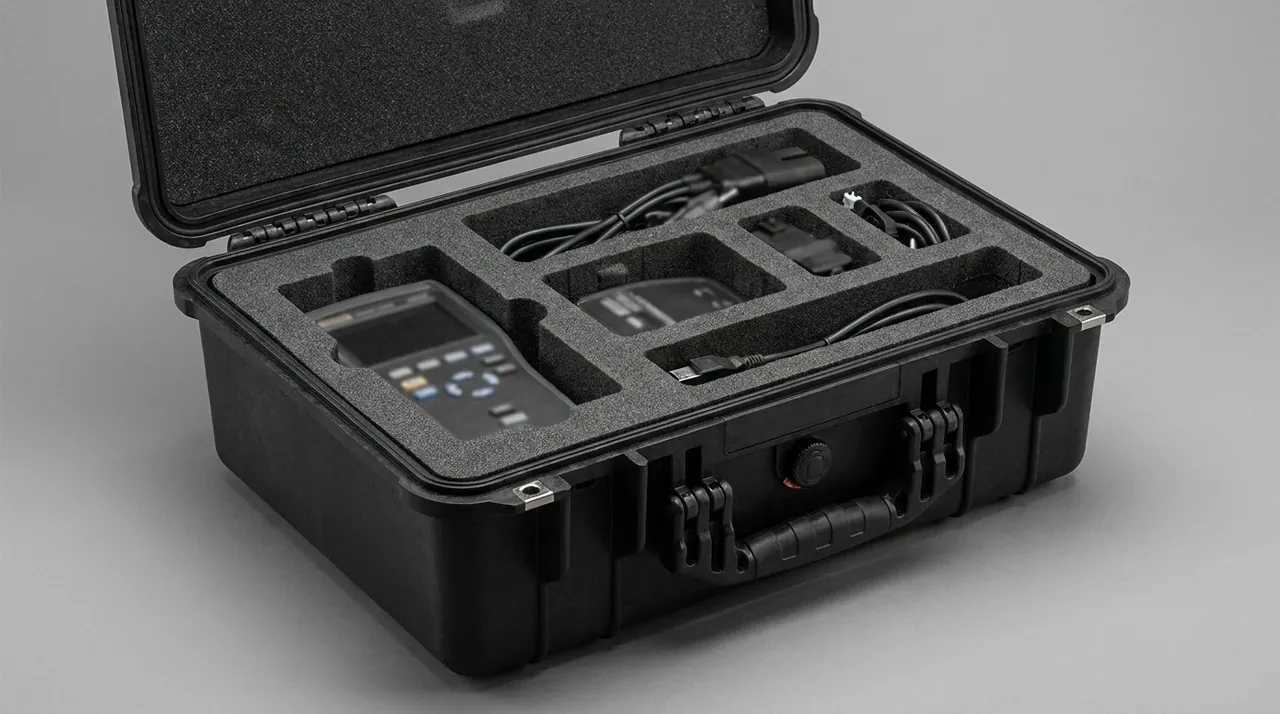
MoSi2 elements carry one more easily overlooked mechanism: low-temperature moisture pesting. MoSi2 oxidizes rapidly in the 400 to 600 C range, known in the industry as pesting, and an element left idle or stored improperly can crumble to powder at the surface and lose function. Once such elements are stored long-term, the packing scheme must therefore state both a dryness requirement and a post-arrival pre-oxidation requirement, typically holding above 1000 C for several hours to grow a dense SiO2 protective film (follow the element maker's recommended curve). If this is left out of the delivery file, the site easily attributes a "new but dead" element to a quality problem.
Five executable measures follow. First, resistance ribbon (wavy strip) and resistance wire must be located piece by piece, using non-metallic claws on the straight sections of the strip. Stacking is prohibited, bundling is prohibited, and rope must never be tied directly around ribbon, because a crush mark becomes a local hot spot and fracture origin at temperature. Second, the gap between ribbon layers should be not less than twice the strip thickness, preventing mutual rubbing under vibration. Third, SiC and MoSi2 rods should be stored vertically or on large-radius curved supports; when laid horizontally the support span must be significantly below the value allowed for the rod diameter, and every support point must have a soft liner. Resting a rod on a hard edge is prohibited. Fourth, the element cell must be dried and fitted with a humidity indicator, and MoSi2 elements in particular should have their own cell with the relative humidity at dispatch recorded. Fifth, terminal rods, ends and connection terminals get separate guards and must never serve as a load or lashing point. When customizing such element cells, JUNZHIJIA normally forms profile-shaped slots to the element outline and makes the slots removable, so the site can lift elements out one at a time from above rather than pulling a whole layer out and dragging neighbouring elements down in the process.
| Element Type | Room-Temperature Mechanics | Primary Failure Mode | Packing Point |
|---|---|---|---|
| --- | --- | --- | --- |
| FeCrAl / NiCr ribbon | Soft, bends easily | Crush marks, bend fracture, interlayer rubbing | Single-piece location, non-metallic claws, no bundling |
| Resistance wire (coiled) | Deforms easily | Coil pitch collapse, local wire break | Mandrel support, axial restraint, separate cell |
| Metallic heating tube | Reasonably rigid | Bent terminal rod, shattered insulator | Terminal guard, independent terminal location |
| SiC rod | Brittle at room temperature | Impact fracture, damaged end electrode | Vertical or large-radius support, end caps |
| MoSi2 rod | Very brittle at room temperature, moisture pesting | Fracture, surface crumbling | Dry cell, humidity record, pre-oxidation on arrival |
Anti-Vibration for Thermocouples, Compensating Cables and Control Components
The temperature accuracy of a brazing furnace depends on thermocouples and the control loop, and these parts fail in a way opposite to structural parts: they do not fear heavy load, they fear high-frequency vibration and small mechanical disturbance. Standard thermocouple accuracy classes are usually graded to IEC 60584 or GB/T 16839, and a type K or N thermocouple that has seen violent vibration and repeated bending develops lattice defects and work hardening in the thermoelements, producing a drift in indicated value. That drift shows no regular pattern in the calibration room and appears only as batch-to-batch variation in braze quality.
Compensating cable protection is equally underrated. The cable extends the thermocouple cold junction to the controller and compensates intermediate temperature. Once its insulation and shield are bent below the minimum bend radius, microcracks form in the copper conductors and a parasitic thermoelectric voltage appears at the transition, so the controller reads a temperature that differs from the actual chamber temperature. Across the 450 to 1150 C brazing range, that offset is enough to change wetting and spreading of the filler metal. The ceramic insulating sleeve of a sheathed thermocouple is a brittle part like an SiC rod, and mutual rubbing of the insulating beads under vibration lowers insulation resistance.
Four executable measures follow. First, the thermocouple body goes into an independent slot with an elastic liner, slot width set at body diameter plus 2 to 3 mm (empirical), so the body is held by the soft liner rather than hammering inside a hard hole. The body must not be used as a lashing load point. Second, bend radius of a sheathed thermocouple follows the maker's specification; when packing, the protective tube ships with the body, and the body must not be coiled tighter to save space. Third, compensating cable is coiled to not less than the maker's minimum bend radius, preferably 10 to 20 times the cable diameter (empirical); after coiling, bind it lightly with a soft tape. Never tie a hard knot, never cinch the bundle with a cable tie, and give the terminals their own protective sleeve with clear marking. Fourth, control components (recorders, temperature control modules, thyristor power units) are treated as precision electronics: vibration-proof, ESD-protected and moisture-protected, with an independent cell and antistatic bubble bag, kept off the floor and away from walls during transport and storage.
Vacuum Sealing Faces, O-Rings and Flange Knife Edges
The sealing system of a vacuum brazing furnace is the first gate for the whole machine's leak rate, yet seal parts are exactly what gets tossed into a case as "small items". Vacuum flanges commonly use the CF (knife-edge metal seal), KF (elastomer clamp seal) or ISO-K pattern. A CF flange seals by plastically deforming a copper gasket against the knife edge, so one burr, one dent or one crossed scratch on that edge will keep leak rate above the design target. When troubleshooting poor vacuum, sites usually suspect the pump set and gauges first, and only at the end discover the flange knife edge, at enormous diagnostic cost.
O-rings fail by a different mechanism and mainly fear three things: light, heat, and permanent compression set. Fluoroelastomer (FKM) and silicone (VMQ) seals age faster under ultraviolet and ozone, crosslink or degrade faster at elevated temperature, and take a permanent compression set under long-term load, losing resilience. An O-ring should therefore not be stored in a compressed state, must not be stored with oils or organic solvents, and must not touch carbon steel directly.
Five executable measures follow. First, CF flange knife edges get a plastic or aluminium guard ring with an inner diameter slightly larger than the edge outer diameter, so nothing can reach the edge directly. Flange faces must never be laid face to face; a divider is mandatory. Second, KF and ISO-K elastomer seal faces get a peelable low-tack protective film, chosen for no adhesive residue, so the seal face does not become a particle source. Third, O-rings are bagged individually by size in a chlorine-free, sulfur-free neutral material, kept dark, and stored as a batch in a cool cell; O-rings in one cell should not be stacked under load, which would cause permanent set. Fourth, metal gaskets (oxygen-free copper, aluminium) are packed separately with their seal faces protected and never mixed with carbon steel, avoiding galvanic corrosion and iron contamination. Fifth, no paper tags or low-density open-cell foam may go inside a seal cell. Use polyester tags or external labeling, because paper and open-cell foam absorb moisture and leave water marks and fibres on sealing faces.
| Seal Type | Key Failure Mode | Packing Requirement | Storage Condition |
|---|---|---|---|
| --- | --- | --- | --- |
| CF knife-edge flange | Edge burr, dent, crossed scratch | Guard ring, divider between faces | Dry, no contact with other metals |
| KF / ISO-K flange face | Seal-face scratch, particle contamination | Peelable protective film | Clean, dust-free |
| O-ring (FKM / VMQ) | Ageing, compression set, swelling | Individually bagged, not stacked | Dark, cool, away from oil and solvent |
| Oxygen-free copper / aluminium gasket | Seal-face oxidation, iron contamination | Separate packing, seal face protected | Dry, isolated from carbon steel |
Door, Viewport and Seal-Groove Closing Accuracy
The furnace door is the most frequently operated moving part of a brazing furnace, and its closing accuracy is set jointly by the door frame, door body, hinges, locking mechanism and seal groove. Door damage in transit and storage follows a very characteristic pattern. When the door body lies flat in a case, the closing face presses directly onto the liner, and any grain of sand resting on the liner presses a mark into the closing face. The viewport glass bends under the door's own weight, and a transit impact can start an edge crack, which then grows into a through crack under thermal stress after heat-up.
Seal-groove damage is more insidious. The groove for an O-ring or sealing cord has a bottom and two side walls that together form the geometric reference for sealing. A burr on the groove mouth scratches the sealing cord during installation, and a scratched cord fails quickly under thermal cycling. A compression mark on the groove bottom shifts the cord compression away from the design value, producing a local leak point at the door.
Four executable measures follow. First, the door closing face (the face mating with the door frame) gets a peelable protective film, and a formed spacer sits between door body and frame so the two machined faces never touch directly. No metal tool or fastener may ever be placed on a closing face. Second, viewport glass is fixed vertically or at a steep angle so it mainly carries in-plane compression rather than bending stress. A soft liner goes between glass and metal frame, and bolts are tightened in a diagonal sequence in several passes to avoid local stress concentration. Third, hinges and locking mechanisms are protected before packing: pins get sleeves, threads get caps. A hinge is a kinematic pair, and any sand that enters accelerates wear and degrades closing repeatability, an argument that parallels the material and life-assessment approach described for toolbox hinges, latches and sealing structures in general protective case design. Fourth, seal grooves are cleaned and checked for burrs before packing, then filmed. Complete sets of sealing cord, retaining strips and fasteners are compartmentalized by size and never mixed.
Protection of Vacuum Pumping Sets and Valves
The pumping system of a vacuum brazing furnace combines rotary vane, Roots, diffusion or turbomolecular pumps with valves and gauges at each stage, forming a chain sensitive to both cleanliness and sealing. These parts are usually balanced and leak-tested at the factory, and two categories of risk during transport and storage cancel that work: rotor and bearing corrosion, and mechanical damage to sealing faces and bellows.
Vacuum pump rotors and chambers are normally coated with protective oil at dispatch, but temperature and humidity cycling over long storage or ocean freight can emulsify that oil and produce surface rust on the rotor and chamber. A turbomolecular pump rotor runs at high speed, so any foreign object entering will cause fatal damage on start-up; its inlet and outlet must therefore stay plugged throughout transport, and the plug is removed only at the last moment before installation. Bellows of bellows valves and poppet valves are thin-wall elastic parts that fatigue-crack under repeated bending or side load, so they must be packed in their natural state and never with other parts resting on them.
Five executable measures follow. First, every pumping component interface is closed before packing with an original protective cap or an O-ring-equipped plug. Tape or cotton waste as a temporary plug is prohibited. The turbopump plug stays in place until installation. Second, the pump body sits in the liner in its original design attitude as marked by the maker. It must not be inverted or laid on its side, which would let oil enter the chamber or seep out through the shaft seal. Third, valve bellows and stems must not carry side load; an independent cell locates the valve, and valve weight is carried by the liner rather than by the pipe connection. Fourth, gauge tubes (Pirani, ionization) are glass or ceramic and are handled as brittle parts, with an independent cell, soft liner and capped connections. Fifth, the complete vacuum set should have its own cell separated entirely from liners and refractory parts, because the dust shed by refractory parts is the most serious contamination source for a vacuum system.
Atmosphere System Parts and Hydrogen Line Safety
Atmosphere-protected brazing furnaces commonly use hydrogen, nitrogen, dissociated ammonia or their mixtures, and the atmosphere system carries one constraint stricter than ordinary industrial parts: no component that will see long-term hydrogen service may leave the packing step with oil, cotton waste or organic residue. Hydrogen has a very low ignition energy under pressure, so oil films, fibres and residual solvent on the inside of piping are all potential ignition and contamination sources. Degreasing and drying must be completed before packing, and the packing material itself must not bleed plasticizer or oil.
Four executable measures follow. First, pressure reducing valves, flow meters, safety valves and solenoid valves are degreased and dried before packing, with capped connections. The float and tapered tube inside a flow meter are glass and must be fixed independently as brittle parts. Second, piping and fittings are compartmentalized by size with their bores plugged against dust; stainless steel tube must not touch carbon steel directly, avoiding iron contamination and galvanic corrosion. Third, hydrogen detectors and flame detector probes are sensing elements and are protected as precision electronics: never stored in the same cell as magnetic parts, and never subjected to violent vibration in transit. Fourth, the set pressure of a safety valve is set by spring preload. Severe vibration in transit will not change the set point but will change the seating state of the disc, so the valve should be function-checked on arrival rather than put straight into service. This point belongs on the unpacking acceptance checklist.
Heavy Furnace Body Parts: Lifting and Saddle Design
Retorts, radiant tube assemblies, complete doors and vacuum chambers are heavy parts, from tens of kilograms to several tonnes each. The load path after packing must run completely from the workpiece into the liner, into the case floor, then into the pallet and the transport vehicle. The most commonly overlooked element in that path is dynamic amplification: on a road, load peaks from uneven pavement reach 1.5 to 3 times the static load (empirical), and the instantaneous impact of setting the case down is higher still. If the liner is designed only for static load, transit produces liner compaction, part displacement and even a cracked case floor.
Four executable measures follow. First, the case floor carries load beams, or a load-bearing pallet carries the load, so heavy parts transfer into the vehicle directly rather than through the case walls and corner fittings. Second, saddle contact area is set by contact stress; the allowable contact stress for soft material against a machined face or a thin-wall cylinder is commonly taken as 2 to 5 MPa (empirical), from which contact area and support width are back-calculated and the calculation kept in the design file. Third, lashing angle stays between 30 and 45 degrees. Vertical downward tightening is prohibited, because vertical lashing only provides friction restraint and will slip once the liner compacts. Fourth, lifting points and the centre of gravity are marked clearly on the outside of the case; for eccentric loading, add counterweight or adjust cell positions to avoid the case tilting during lifting. A long heavy part must not be suspended from a single support or allowed to sag at mid-span; increase the number of support points so the span stays within a reasonable range.
Heavy-part lifting practice belongs in the work instruction as well. Use the part's own lifting lugs or a wide sling cradling both ends of the cylinder. Never run wire rope or chain directly over a thin-wall cylinder or a flange sealing face, and never place a lifting point on a heating element, thermocouple sleeve or vacuum port. Illustrating these rules works far better than verbal briefing. Where retorts and liners ship together, the liner should be stored upright on its own and must never be stacked on top of the retort, because the liner's compressive capacity is far below the retort's.
Insert Compartmentalization, Humidity and Dew-Point Control
The insert of a brazing furnace parts case is not decoration; it is the carrier of the entire protection scheme. It has to satisfy four functions at once: flexible location for brittle parts, continuous support for thin-wall parts, a controllable-humidity closed micro-environment for moisture-sensitive parts, and electrical and chemical isolation between dissimilar materials. EVA, polyurethane and polyethylene differ widely in hardness, resilience and moisture behaviour, and the selection logic can be followed from the discussion of hardness grades and machining tolerance in custom EVA foam insert processes, then re-verified against the part families of the specific project.
Four compartmentalization criteria follow. First, physical separation takes priority over soft isolation: dissimilar materials are separated by a hard divider with a soft gasket on top forming a weak seal, rather than by a single soft pad. Second, humidity zoning: liner and element cells get active moisture control with humidity indicator cards and low-shedding desiccant; the seal cell is dry and dark; the vacuum parts cell is clean and dust-proof. Third, weight distribution: heavy parts sit near the geometric centre of the case and near the load beams, while light and brittle parts go around the perimeter, avoiding a centre-of-gravity shift that destabilizes lifting. Fourth, serviceability: desiccant and humidity cards should be reachable from outside or from the top without opening every cell.
Executable humidity and dew-point magnitudes can be given. During storage, relative humidity inside the case for general brazing furnace spares should be kept below 60 percent, and liner and MoSi2 element cells below 40 percent (empirical). Where a project carries specific vacuum or dew-point targets, the purchase specification should state the in-case humidity target and the arrival inspection method rather than leaving the judgement to site experience. These values are design control targets rather than performance guarantees: actual behaviour depends on storage duration, the climate of the transport corridor and the desiccant replacement interval.
Post-Arrival Bake-Out Curve and Heating Requirements
What makes brazing furnace parts special is that packing does not end at unpacking; it ends at first heat-up. Whether the case did its job can only be verified by the bake-out curve. A new furnace, a furnace with a replaced liner, or a furnace idle for a long period all hold appreciable physical and chemically bound water in the lining and castable, which must be driven off in staged heating, or the spalling and cracking described earlier is certain.
Four executable points follow. First, staged heating: a low-temperature stage (100 to 200 C) holds long enough to remove physical water, a mid-temperature stage (300 to 600 C) rises slowly to remove chemically bound water, and the high-temperature stage goes to working temperature per process. Hold times and ramp rates at each stage should be set from the lining supplier's recommended values and the lining thickness, not copied from another furnace type. Second, control the ramp rate: thick castable and lightweight brick have different allowable rates. Brick can go faster while castable must go slower, because residual water in castable is harder to remove. Third, ventilation and exhaust: keep the chamber exhaust path open throughout bake-out so vapour leaves promptly instead of condensing in a cold zone and running back. Fourth, MoSi2 pre-oxidation: new or long-stored MoSi2 elements should be held above 1000 C for several hours to grow an SiO2 protective film, following the element maker's recommendation, and this must not be merged into the same operation as lining bake-out.
Where a project also involves post-braze workpiece processing or a linked heat-treatment furnace, the bricking and heat-up notes can be read alongside industrial furnace cases for lining and burner protection. The two share the principle that linings fear moisture more than impact, but a brazing furnace usually has a stricter ramp requirement, because its temperature uniformity directly determines braze quality.
| Stage | Temperature Band (Example) | Main Purpose | Prohibited |
|---|---|---|---|
| --- | --- | --- | --- |
| Low temperature | 100-200 C | Remove physical water | Fast ramping, long dwell in mid band |
| Mid temperature | 300-600 C | Remove chemically bound water | Skipping dwell and going straight up |
| High temperature | Per process | Reach working temperature | Entering high band before water is driven off |
| MoSi2 pre-oxidation | Above 1000 C | Grow SiO2 protective film | Merging with lining bake-out |
Labeling, Inspection, Unpacking Acceptance and Test Basis
Packing labels and unpacking acceptance are the last step that lands all the earlier design on site. Outer labels should follow GB/T 191 and GB/T 13384, marking fragile items, this way up, keep dry, no rolling, and stacking limits, along with case number, gross weight, centre of gravity and lifting points. Where several cases ship together, each case should be marked with its part family and the furnace station number it belongs to, so the site does not fit furnace A's retort to furnace B.
Unpacking acceptance should follow a checklist by part family: liner modules for chipping and moisture content, checked by spot reading with a portable moisture meter; retorts and radiant tubes for roundness and wall thickness, checking for dents; heating elements inspected piece by piece for cracks and end damage, with the humidity card reading recorded; thermocouples and compensating cable checked for appearance and continuity, and for clear polarity marking; vacuum flanges checked for knife-edge burrs, O-rings for ageing cracks; doors checked for closing-face marks and viewport glass for edge cracks; vacuum and atmosphere parts checked for intact plugs and any sign of moisture. Any nonconformance should be recorded and notified to the supplier rather than absorbed on site.
On test basis, the purchase specification should separate the purpose of three families. The ISTA and GB/T 4857 series evaluate a packed case under vibration, impact and stacking in transport. ASTM D4169 designs test sequences by distribution cycle. GB/T 10125 (neutral salt spray) provides a comparative ranking of corrosion resistance for case hardware and liner-plus-workpiece contact combinations. It should be stated clearly that salt spray testing gives a ranking between schemes, cannot be used to project field life directly, and does not support any claim of certification. Likewise, MIL-STD-810H clauses are used in this field only as environmental test method reference, for example to define the conditions and magnitudes of vibration and temperature-humidity cycling, and do not mean the product holds a military certification. On brazing furnace parts case projects, JUNZHIJIA normally supplies seals, plugs, desiccant and humidity cards by part family, and can provide inspection documents for case dimensions, insert structure and hardware. Insert plans and test recommendations are issued against drawing dimensions, part weight distribution and transport route, with OEM/ODM and volume supply support.
FAQ
Q: What does a brazing furnace liner (ceramic fiber module) fear most in transit, and why is moisture worse than impact?
A: It fears three things: edge chipping, moisture uptake and compression set, and moisture has the most serious and most easily hidden consequence. Ceramic fiber modules commonly run 128 to 220 kg/m3 in bulk density (typical values) with very low compressive strength, so the self-weight of a stack can chip the bottom layer. Chipping, however, is usually visible at unpacking and can be claimed or replaced promptly. Moisture behaves differently. Lightweight brick and fiber modules have high apparent porosity and can absorb significant water within days at 80 percent relative humidity, yet appear perfectly normal at unpacking. During the first bake-out, free water in the pores flashes to steam, and when vapour pressure exceeds material strength it produces a spall crater. The wall is thinner there, becomes a hot spot at temperature, and in parallel the compressed fiber does not recover, so joint density after bricking stays low, heat short-circuits through the joints, shell temperature rises and energy use follows. The packing objective is therefore no compression, no moisture, no abrasion: each module in its own moisture-proof cell or a single layer on a tray, surface contact only, low-shedding desiccant plus a humidity indicator card, and for ocean freight an agreed absorption test method for the liner material.
Q: Why can a brand-new MoSi2 heating element fail while in storage, and how should packing prevent it?
A: MoSi2 (molybdenum disilicide) has a failure mechanism tied directly to temperature exposure: it oxidizes rapidly in the 400 to 600 C range, known in the industry as pesting, and an element left idle or stored improperly can crumble to powder at the surface and lose function. So the element is not damaged by being struck; it is destroyed by moisture and temperature cycling acting together. Packing and delivery should address three points. First, the element cell needs active moisture control with a humidity indicator card, MoSi2 should have its own cell, and the relative humidity at dispatch should be recorded. Second, the element body is extremely brittle at room temperature and must be stored vertically or on large-radius curved supports with soft liners at every contact point; resting it on a hard edge is prohibited, and the terminal rod must never be a load point. Third, the post-arrival pre-oxidation step must be written into the delivery file: new or long-stored elements should be held above 1000 C for several hours to grow a dense SiO2 protective film, following the element maker's recommended curve, and this must not be merged with lining bake-out. With these three steps the site will not misattribute a dead element to a quality defect.
Q: Why must FeCrAl or NiCr resistance ribbon never be bundled for transport?
A: Resistance ribbon and wire are relatively soft in the annealed condition, and bundling causes two irreversible types of damage. The first is crush marks. A groove pressed into the strip by rope or a cable tie is merely cosmetic at ambient temperature, but once energised the reduced cross-section raises local resistance and creates a hot spot, and over time fracture begins there, with the fracture location matching the crush mark. The second is interlayer rubbing. In a bundle, adjacent ribbon surfaces micro-move continuously under transport vibration, grinding off surface oxide and metal debris. This both contaminates the element surface and locally thins the strip. The correct method is single-piece location: non-metallic claws grip the straight sections, layer-to-layer clearance is not less than twice the strip thickness, and the ribbon is never used as a lashing load point or mixed with other parts. The coiled section of resistance wire should additionally be supported on a mandrel with axial restraint, preventing the coil pitch from collapsing under vibration, because a collapsed coil changes the heat dissipation condition when energised and becomes another failure origin.
Q: For vacuum furnace CF flange knife edges and O-rings, how do protection priorities differ?
A: The two are protected against completely different hazards, and mixing them is a common error. A CF flange seals by plastically deforming a copper gasket against the knife edge, so any burr, dent or crossed scratch on that edge keeps leak rate above the design target, and the priority is isolating foreign objects: guard the edge with a plastic or aluminium ring, never lay flange faces directly against each other but always with a divider, and never mix with carbon steel parts to avoid iron contamination. O-rings fail instead by material ageing and permanent compression set and mainly fear light, heat and long-term load, so they must be bagged individually in a chlorine-free, sulfur-free neutral material, stored as a batch in a cool, dark cell, not stacked within one cell, and kept away from oils and organic solvents. In addition, neither cell may contain paper tags or low-density open-cell foam: both absorb moisture and leave water marks and fibres on sealing faces, becoming particle sources. At acceptance, inspect CF knife edges under magnification for crossed scratches, inspect O-rings for ageing cracks and permanent deformation, and inspect metal gaskets for seal-face oxidation.
Q: How should a thin-wall retort (muffle) be supported inside a case so it does not deform?
A: Two principles matter most: continuous multi-point support, and staying clear of welds. A thin-wall cylinder (commonly 2 to 6 mm wall, typical values) has very low room-temperature stiffness, so a cylinder 400 to 800 mm in diameter and 2 to 6 m long that is simply supported at both ends with an unsupported mid-span will take permanent ovality from self-weight and transit impact. The executable method is a curved saddle matched to the cylinder outside diameter, with a soft elastomer liner on the inner arc, contact arc length between 60 and 90 degrees of the circumference (empirical), and three to five saddles along the span so mid-span deflection stays small. Saddle positions must avoid welds and flanges, staying not less than 30 mm from the weld edge, so support reaction does not act directly on the heat-affected zone. Axial restraint is also required: a fixed stop at one end and an elastic floating stop at the other, letting the elastic element absorb transit impact. Without it, the cylinder slides across the saddles and concentrates friction at one point. For lifting, never cradle a thin-wall cylinder directly with wire rope or chain, and never use flange bolt holes as lifting points.
Q: If compensating cable has been bent, does it really affect furnace temperature accuracy?
A: Yes, and the resulting offset is hard to reproduce in a calibration room, so it finally appears only as batch-to-batch variation in braze quality. Compensating cable extends the thermocouple cold junction to the controller and compensates intermediate temperature. Once its copper conductors and insulation are bent below the minimum bend radius repeatedly, microcracks form in the conductors and a parasitic thermoelectric voltage appears at transitions, so the controller reads a temperature with a fixed or slowly drifting offset from the actual chamber. Across the 450 to 1150 C brazing range that offset is enough to change wetting and spreading of the filler metal, appearing as local incomplete penetration or filler run-off. The protection method: coil to not less than the maker's minimum bend radius, preferably 10 to 20 times the cable diameter (empirical); bind lightly with soft tape after coiling; never tie a hard knot and never cinch the bundle with cable ties; protect terminals with their own sleeve and mark them clearly; and store separately from thermocouple bodies so that neither bodies nor tools rest on the cable. On arrival, measure continuity and insulation and verify polarity marking.
Q: Why can't the post-arrival bake-out simply copy another furnace type's heating curve?
A: Because the moisture characteristics and wall thickness of the lining determine the allowable ramp rate, and lining composition differs substantially between furnace types. A brazing furnace chamber is lined mainly with ceramic fiber modules, lightweight insulating brick and castable preformed blocks. Brick and fiber modules tolerate faster ramping, while castable must go slower with longer holds because residual water is harder to remove. The purpose of bake-out is also broader than removing physical water: the low-temperature stage (100 to 200 C) mainly removes physical water and the mid-temperature stage (300 to 600 C) mainly removes chemically bound water, and hold times at each stage should come from the lining supplier's recommended values and the lining thickness. Copying another furnace's curve easily ramps the mid stage too fast and leaves internal cracks. Keep the exhaust path open throughout bake-out so vapour leaves promptly instead of condensing in a cold zone and running back. In addition, MoSi2 pre-oxidation (holding above 1000 C for several hours to grow an SiO2 film) is a separate operation and must not be merged with lining bake-out, since the two differ entirely in temperature target and dwell logic.
Q: What role do GB/T 10125 salt spray and MIL-STD-810H play in selecting a brazing furnace parts case?
A: Their role is to provide test methods and scheme ranking, not to issue certifications. The GB/T 10125 neutral salt spray test accelerates corrosion of case hardware such as hinges, latches and corner fittings, and of liner-plus-substrate contact combinations, for example comparing different stainless grades or coating systems under identical conditions and measuring the change in hinge opening torque before and after exposure. That ranking is more persuasive than appearance photographs alone. It cannot, however, project field life directly, because salt spray cabinet conditions are not equivalent to a coastal workshop or humid warehouse where daily condensation, abrasive dust and thermal cycling also act. MIL-STD-810H clauses are used here only as environmental test method reference, to define vibration and temperature-humidity cycling conditions for design and verification, and do not mean the product holds a military certification. State the role of each basis in the purchase specification so it is not misread as a qualification claim.
Conclusion and Related Reading
Four rules govern a brazing furnace parts case: liner modules in independent moisture-proof cradles, retorts and radiant tubes on curved multi-point saddles, heating elements segregated by material, and instrumentation and seals protected from vibration. JUNZHIJIA builds liner dry cells, retort load cells, element cells and seal cells as separate units and supplies seals, plugs, desiccant and humidity cards by part family, with OEM/ODM support.
Related Reading