

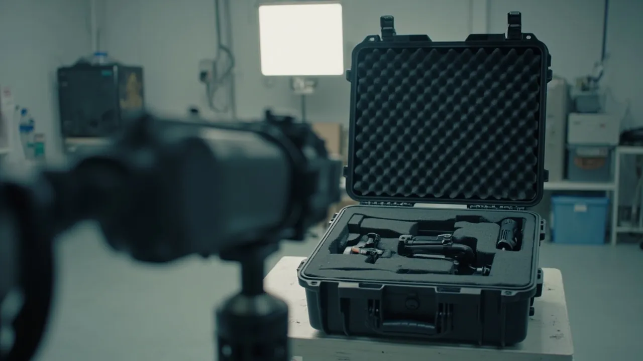
In heat pipe and heat-transfer element logistics, the dominant damage mode is not fracture but deformation and fin collapse. A heat pipe bows at mid-span, fins are crushed and folded so that air-side resistance rises and heat-transfer area is lost, and end seals and header connections are struck and lose their sealing datums. The core design logic for a heat pipe equipment case is therefore multiple form-fitting supports, a suspended non-compressed fin zone, focused end protection and moisture plus corrosion control, not simply a thicker cushioning layer. The conclusion: heat pipes and fin components should be zoned by stiffness, supported at a number of points determined by length, protected with no compressive load on the fin field, and fitted with end sleeves, with performance verified against the GB/T 4857 and ISTA test series. JUNZHJIA supplies this class of case with custom inserts, OEM/ODM programmes and volume production to heat pipe manufacturers, heat exchanger suppliers, waste-heat recovery contractors and export traders.
Transport of heat pipes and finned components has three particular difficulties. First, the fin field is a low-stiffness, high-density structure: individual fins are often 0.1 to 0.5 mm thick at 1.5 to 5 mm spacing, so any lateral pressure folds whole rows, and restoring a folded fin field is essentially never economic. Second, a heat pipe is a sealed component containing a working fluid: deformation of the tube disturbs the uniformity of the internal wick and the vapour channel, which affects isothermality, and severe impact can even damage the fill seal. Third, heat-transfer element performance is highly sensitive to geometric precision: fin pitch, tube bundle layout and flow cross-section all feed directly into heat transfer and air-side resistance. This article gives protection grades, support methods, insert materials, sealing and test references by component category, with comparison tables, an acceptance method and a FAQ section for thermal engineers and procurement staff.
Table of Contents
- 1. Heat Pipes and Fins: Why Deformation Control Comes First
- 2. Heat-Pipe Component Families and Protection Grades
- 3. Heat Pipe Cases: Gravity, Capillary and Vapour Chamber Types
- 4. Finned Tubes and Fin Bundles: Collapse Mechanism and Protection
- 5. Heat-Transfer Elements: Plate, Plate-Fin and Spiral
- 6. Headers and Distribution Pipes
- 7. Vacuum and Working Fluid: The Special Risks of Heat Pipes
- 8. Long and Thin-Walled Parts: Multi-Point Support and Suspension
- 9. Moisture, Corrosion and Cleanliness
- 10. Insert Materials and Support Methods Compared
- 11. Sealing, IP Ratings and the Transport Environment
- 12. Transport Test References and Verification Methods
- 13. Inspecting Long Cases on Arrival
1. Heat Pipes and Fins: Why Deformation Control Comes First
Three engineering facts set the frame.
First, fins resist crushing far less than they resist bending. Along the height of a fin the material is a very thin sheet, while along its length it is a continuous strip. It manages in-plane bending reasonably but has very little resistance to crushing perpendicular to the fin plane. Any contact pressure perpendicular to the fin plane - a strap, a timber batten, the self-weight of an adjacent component - folds rows of fins. In practice, as long as contact pressure is concentrated at a few points, several rows of fins can progressively fold under transport vibration, and the folding is irreversible.
Second, heat pipes are more sensitive to bending than to scratching. A heat pipe normally contains a wick structure (grooves, mesh or sintered powder) and a working fluid. Once the tube bends, the continuity of the wick may be affected and the vapour channel cross-section changes, degrading isothermality and raising thermal resistance. This performance loss leaves no external trace but shows up directly in heat transfer. The governing transport metric for a heat pipe is therefore straightness.
Third, the geometric precision of a heat-transfer element is part of its performance. For a finned tube bundle, a change in fin pitch changes the air-side flow area, which shows up as higher air-side resistance and greater fan power. For a plate-fin exchanger, folded fins mean blocked channels. So "only a few fins got bent" has a definite performance cost in real engineering.
Taken together, a heat pipe and heat-transfer element case should be designed on the principle that deformation control takes priority over cushioning: structurally, location and support dominate; in materials, no crushing of fins is a precondition; environmentally, moisture and corrosion control are the safeguard.
2. Heat-Pipe Component Families and Protection Grades
Grading by geometric fragility, length, internal state and weight covers the great majority of heat pipe and heat-transfer element scenarios.
| Protection grade | Typical components | Dominant failure mode | Support and insert strategy | Recommended case form |
|---|---|---|---|---|
| --- | --- | --- | --- | --- |
| H1 Fin field | Finned tubes, finned tube bundles, plate-fin cores | Fin collapse, channel blockage | No compression on the fin field; end plates carry load; soft lateral location | Medium rigid case, end-loaded with suspended sides |
| H2 Tube body | Gravity heat pipes, capillary heat pipes, vapour chambers | Bending, seal impact, reduced isothermality | Multiple half-round cradles plus end sleeves | Long case or frame case with multi-point support |
| H3 Plate type | Plate heat exchanger plates, plate pairs, gaskets | Plate deformation, gasket groove impact | Stand on edge, edge-loaded, plate face isolated | Medium rigid case with vertical rack |
| H4 Structural | Headers, distribution pipes, frames, connecting flanges | Bending, coating damage, port impact | Half-round cradle plus hard stops plus port caps | Heavy-duty case or frame case |
After grading, one operating rule must be emphasised: the fin field of an H1 component must never serve as a load-bearing face. This is the key difference between a heat pipe case and a general equipment case. The correct approach is to pass load through the stiffer end plates, tubesheets, headers or frames, keeping the fin field suspended or laterally located only, with no normal pressure applied.
For H2 heat pipes, the number of support points follows from the length. The practical rule is to derive support spacing from a maximum deflection of about L/1000; for a 3 m heat pipe this usually means 0.8 to 1.2 m spacing. Use half-round cradles matched to tube diameter with 5 to 10 mm of soft padding at the contact face, so that line contact does not produce local indentation. For heat pipes whose wick structure is already formed, avoid concentrated load at mid-length, because that region is most sensitive to internal disturbance.
3. Heat Pipe Cases: Gravity, Capillary and Vapour Chamber Types
Heat pipes divide by return mechanism into gravity types (thermosiphons), capillary types including grooved, mesh and sintered constructions, and vapour chambers, which are flat plate heat pipes. Transport risks differ slightly between them.
Gravity heat pipes are usually long and often operate close to vertical. In transit, avoid long periods of horizontal storage under concentrated load, because a long tube laid horizontally has its maximum mid-span deflection. If horizontal transport is unavoidable, increase the number of cradles. Gravity heat pipes are less sensitive to attitude since they do not depend on a capillary structure, but they should be protected from severe shock that could dent the tube.
Capillary heat pipes are the most bend-sensitive. Bending alters the geometric relationship between the wick and the vapour channel and therefore affects the heat transport limit. Protection points: multiple cradles, no concentrated load at mid-length, and no strap pulled directly around the tube. Leave the tube slightly free between cradles rather than creating multi-point rigid clamping that produces local stress concentration.
Vapour chambers are flat plate structures with an internal cavity and wick, large in area and thin in section. Their failure mode is plate face indentation plus damage to the edge seal. Protection points: edge-loaded with a suspended plate face, cavity depth slightly greater than plate thickness, and soft lateral location at the edges. Large vapour chambers should not be laid flat and stacked.
The end seal is a shared sensitive point for all heat pipes. Formed by welding or crimping, it is the sealing datum. Protection points: soft sleeves or purpose-made caps at both ends, with the sleeve covering the seal area and extending 30 to 50 mm beyond it; the seal area must never serve as a support point or a load path.
For heat pipes that have completed performance testing for isothermality and thermal resistance, keep the test label on each item under seal and verify the label before breaking the seal on arrival. Where the project specifies a transport attitude, for example keeping the pipe vertical, mark it prominently on the case and supply handling instructions.
On internal working fluid and vacuum state: a heat pipe normally leaves the factory with the interior at negative or specific pressure and containing a working fluid. Severe impact in transit can damage the tube and thereby affect sealing and internal state. The case's responsibility is to prevent mechanical shock and external environmental attack, not to maintain the internal state of the heat pipe. Where internal state matters, it must be assured by the manufacturer in the design of the component itself.
4. Finned Tubes and Fin Bundles: Collapse Mechanism and Protection
The collapse mechanism is not complex: when a force acts perpendicular to the fin plane, the fin as a thin sheet buckles elastically, and once the critical value is exceeded it enters plastic deformation that does not recover on unloading. Among closely spaced fins, one folded fin presses on its neighbour, producing a domino effect. Fin damage therefore tends to occur in whole rows rather than on single fins.
From this mechanism, protection reduces to three rules.
First, avoid any normal pressure perpendicular to the fin plane. This includes never strapping directly across the fin field, never pressing timber or steel bars transversely onto a fin bundle, and never stacking two fin bundles fin-face to fin-face.
Second, load must pass through the end plates or frame. The end plate or tubesheet of a finned tube is the stiffer region and should be the primary load-bearing point. For a bundle, support at both end plates, with a mid-support beam that does not touch the fins and transmits force through the end plates or a dedicated fixture.
Third, a bundle can use soft lateral location instead of normal clamping. Lateral stops limit transverse movement without applying force perpendicular to the fin plane, controlling displacement while avoiding crushing.
For finned tubes with bends, such as L-type and U-type returns, the bend region is also fragile; leave a void outside the bend in the cavity so it cannot contact the case wall.
For components with slight existing fin damage, such as repaired items, mark the case as fin-straightened and not to be compressed, and add extra lateral isolation inside the cavity.
One further detail: fin edges are sharp. Under vibration a fin can cut into insert material, generating debris that then contaminates the fin field. Choose cut-resistant material at the fin contact face, or add an isolation sheet.
5. Heat-Transfer Elements: Plate, Plate-Fin and Spiral
Plate heat exchanger plates are thin corrugated metal sheets, normally assembled in pairs with gaskets. Their failure modes are local plate deformation that misaligns the corrugations, and impact damage to the gasket groove that destroys sealing. Protection points: stand on edge, load at the edges, isolate the plate faces. Plates must be separated by soft dividers and must never touch metal to metal; they should not be laid flat and stacked, because self-weight and stacking pressure compress the corrugations. Where plates are already assembled into pairs, restrain them as a pair so the assembly cannot come apart inside the case.
Plate-fin heat exchanger cores are the archetypal H1 fin-field component. Their fins are dense and channels are small, so collapse or blockage causes unrecoverable performance loss. Protection points: use the core end heads or side plates as load-bearing points; keep the fin field suspended; support and laterally locate the whole core; never apply pressure to the core surface. For cores that have passed pressure or leak testing, keep the labels and protect the ports from impact.
Spiral heat-transfer elements are usually long or helical tube bundles, combining H2 and H4 characteristics. The stiffness of a helical bundle differs greatly between axial and radial directions, so it tends to compress axially or deform radially in transit. Protection points: insert internal shaping support such as a removable mandrel or annular support, and use external multi-point cradles; never leave both ends unsupported while the self-weight acts at mid-span.
For all three element types, the shared acceptance metric is geometric recoverability: plate pitch, fin pitch and channel dimensions. Sampling these on arrival is recommended rather than relying on visual inspection alone.
6. Headers and Distribution Pipes
Headers and distribution pipes are the skeleton parts of heat pipes and heat-transfer elements, usually long tubes or welded assemblies with multiple stubs and ports. Their failure modes are bending and port impact.
Supporting a long header follows the same logic as a heat pipe: multiple half-round cradles, end sleeves, and no concentrated mid-length load. For a header with multiple stubs, the stubs are the most exposed features and should have removable U-shaped protective blocks or soft sleeves. Bevels and sealing faces on the ports need protection too: fit caps and mark the port orientation on the case.
Distribution and spray pipes often carry small orifices that are sensitive to contamination. Purge and cap before packing; do not use debris-shedding insert materials; include a humidity indicator card in the case.
For welded header assemblies, the same deformation-control thinking that applies to welding also applies to transport: transport does not create thermal stress, but it can create plastic deformation that shows up later as joint misalignment on site. Restraint should therefore be hard stops plus elastic support rather than rigid clamping.
For very long headers above 4 m, use a frame-type long case: the steel inner frame carries the load, the outer shell only shields and seals, and the frame connects to the case floor through elastic pads that interrupt the shock transmission path. This separation of load bearing from weather protection is especially effective for long thin-walled parts; see cushion liner case structural solutions.
7. Vacuum and Working Fluid: The Special Risks of Heat Pipes
A heat pipe belongs to the class of components that are sealed on the outside and contain a working fluid internally, including gravity heat pipes, capillary heat pipes with grooved, mesh or sintered wicks, vapour chambers and loop heat pipes. One transport risk has no counterpart in ordinary machined parts: the internal state is sensitive to external disturbance.
The boundary must be clear: a heat pipe or heat-transfer element case is an outer transport packaging container. It does not participate in the design or manufacture of the heat pipe or heat exchanger itself, and it is not a pressure part or a vacuum component. The case is responsible only for mechanical and environmental protection during transport and storage. Vacuum level, working fluid charge and wick performance are assured by the manufacturer in the design and manufacture of the component; a packaging case cannot substitute for those requirements. If a component suffers severe impact in transit, the tube seal or internal structure may be affected, so the objective of packaging is to hold shock and deformation below the level that would damage the tube, not to maintain vacuum.
In engineering practice, three transport risks relate most directly to internal state.
The first is tube denting and bending. A change in tube cross-section squeezes the internal wick and reduces the vapour channel, which shows up directly as reduced heat transport performance. The protection priority is to eliminate point loads and concentrated mid-length loads.
The second is seal damage. The fill seal is the sealing datum; once damaged, working fluid may escape. The protection priority is end sleeves and no load at the ends.
The third is prolonged high-temperature exposure. For some working fluids, internal pressure rises with temperature and imposes additional stress on the tube wall and seal. On multi-climate routes, container interior temperatures can be significantly above ambient. Choose temperature-resistant case materials, avoid prolonged storage in direct sun, and mark temperature cautions on the case where necessary. For material behaviour across a wide temperature range see wide-temperature-range case solutions.
8. Long and Thin-Walled Parts: Multi-Point Support and Suspension
Heat pipes, headers and finned tube bundles share the characteristic of being long, thin, or both. Three practical rules govern support design.
Rule one: the number of support points is governed by deflection, not by weight. Many designs are configured around whether the supports can carry the weight, and the weight is carried while deflection exceeds tolerance. Instead, state the allowable deflection, for example L/1000, and derive support count and spacing from it.
Rule two: support contact should be an area, not a line. Use half-round contoured cradles for round tubes and area-contact saddles for square or flat sections, with soft padding at the contact face. Line contact creates local indentation, and under prolonged vibration the indentation spreads.
Rule three: allow limited freedom and never clamp rigidly. A long part expands and contracts with temperature, and if both ends are rigidly fixed the resulting restraint stress can equal or exceed the transport load. Use one end fixed plus one end sliding, or multiple elastic supports.
For thin-walled parts there is one more rule: never let another component rest on a thin-walled part. This happens constantly in mixed loads, with a heavy item placed above a thin-walled item, and every bump in transit delivers an impact. Compartmentalise the load and mark stacking direction and this-side-up on the case.
For long parts that circulate between several project sites, provide adjustable cradle positions inside the case so that one case can accommodate different lengths, for example through multiple cradle mounting holes. Such generalisation measurably reduces the number of cases needed for a multi-specification project; for cost considerations see protective case mould cost analysis.
9. Moisture, Corrosion and Cleanliness
Moisture protection for heat pipes and heat-transfer elements arises from three specific problems.
The first is water retained between fins. Fin spacing is small, so once water or condensate enters the case it is held between fins by capillary action and drains poorly, creating a persistently humid environment. For aluminium fins this accelerates corrosion; for copper tube with aluminium fins it can also drive galvanic corrosion between copper and aluminium, with aluminium as the anode.
The second is corrosion of machined faces and ports. Header ports, bevels, threads and flange sealing faces corrode readily. Apply a peelable rust-preventive film or an environmentally acceptable rust-preventive grease, and mark the case as requiring cleaning before installation. Ordinary machine oil is not suitable as a long-term rust-preventive layer.
The third is dissimilar metal contact. Copper, aluminium, stainless steel and carbon steel should be isolated inside the same case to prevent galvanic corrosion; soft insulating dividers work well.
On cleanliness, small-channel features such as distribution pipes, spray pipes and fin passages should be purged and capped before packing. Do not let wood, felt or open-cell foam touch passage components, and keep the packing area away from cutting and grinding stations. The order of cleaning and drying matters: components must be fully dried before the case is closed, otherwise residual liquid becomes a corrosion initiation site inside a sealed volume.
For components held in long-term storage, use sealing plus desiccant plus a humidity indicator card and check the card periodically; case gaskets should also be inspected and replaced on a cycle. For long-term care see how to clean and maintain a protective case and protective case service life assessment.
10. Insert Materials and Support Methods Compared
For heat pipes and heat-transfer elements, insert material selection has three hard constraints: it must not crush fins, must not shed debris into passages, and must not absorb moisture and become an internal water source.
| Insert material | Stiffness and support | Suitability for fins | Cleanliness | Suitable components | Cautions |
|---|---|---|---|---|---|
| --- | --- | --- | --- | --- | --- |
| Closed-cell precision-milled EVA | Good support, precisely located cavities | Good; can be relieved | High | Heat pipe cradles, header location | Needs desiccant in humid conditions |
| High-density closed-cell PE blocks | High stiffness, good load capacity | Fair; needs a soft pad | Medium to high | End plate support, frame pads | Must not touch fins directly |
| Self-skinning PU foam | Excellent conformity | Good; can be relieved | Moderate | Irregular bundles, bend sections | Control density consistency |
| Nitrile or CR foam | Good cushioning, oil resistant | Good | Medium to high | Oily parts, port protection | Higher cost |
| Low-density PE pearl foam | Weak support | Poor; sheds debris | Low | Void fill (H4 only) | Keep away from fins and passages |
| Felt or non-woven | Weak support | Fair | Low; sheds fibres | Surface barrier (H4 only) | Absorbs moisture, needs protection |
| Timber support blocks | High stiffness | Poor | Low | Internal support in frame cases | Never touch fins or stainless parts |
The selection principle can be summarised as choose material by load-bearing location and use relief at the fin field: load-bearing locations such as end plates, tubesheets and headers may use stiffer material as long as a soft pad is added, while the fin field requires a relieved design in which the cavity is void or uses a very soft separator sheet, with no normal pressure.
For support method, the recommended combination is end support plus multiple cradles plus soft lateral location. End support carries the principal load, multiple cradles control deflection, and soft lateral location controls transverse movement. Together they give reliable restraint without crushing the fin field. For detailed comparisons between materials and structures see case foam material comparison and cushion liner case structural solutions.
11. Sealing, IP Ratings and the Transport Environment
Case protection levels are defined by IEC 60529, and the identical Chinese standard is GB/T 4208. Heat pipe and heat-transfer element cases typically involve two levels, chosen by actual exposure.
| Rating | Meaning | Typical scenario | Configuration |
|---|---|---|---|
| --- | --- | --- | --- |
| IP65 | Dust tight, protected against water jets | In-plant movement, indoor storage, covered road transport | Silicone gasket plus desiccant plus humidity indicator card |
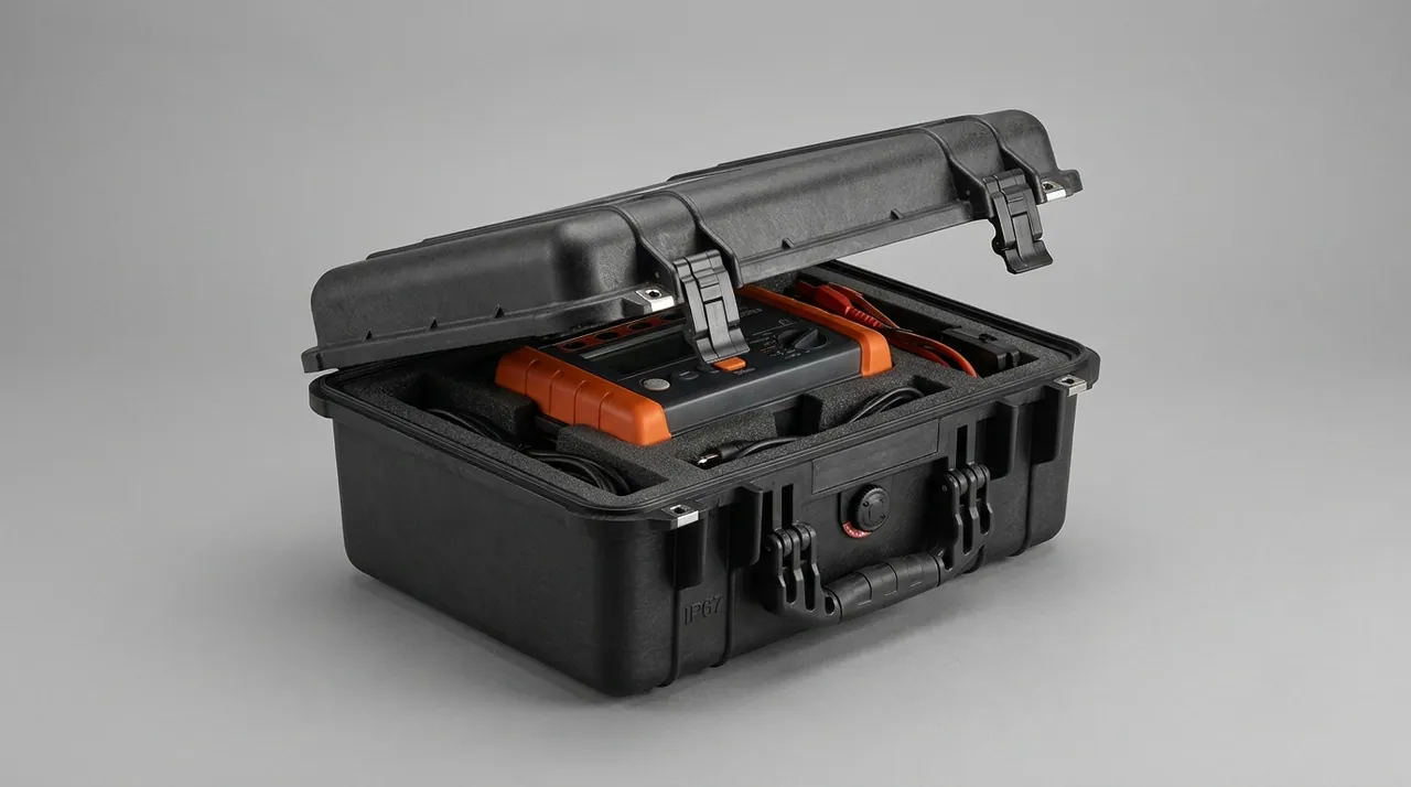
| IP67 | Dust tight, protected against temporary immersion | Ocean freight, open yards, rainy-season long haul, intermodal | Reinforced seal plus pressure equalisation valve plus desiccant |
The three critical parameters of seal design are gasket material and hardness, compression ratio, and uniformity of clamping after closure. Gaskets are commonly silicone or EPDM with compression at 20 to 30 percent. The longer the case, the harder it is to guarantee mid-span clamping force, which calls for more latches or a reinforcing beam. For the combined design of latch and seal see toolbox hinge and latch sealing structure.
One physical effect is easily overlooked: on multi-climate routes a long case develops a larger structural stress along its length from the internal-external pressure differential, especially when the seal is good and internal volume is large. The differential can force the gasket into the case, bulge the side walls, and even make opening difficult. The answer is a pressure equalisation valve: it allows gas to exchange slowly and equalise the differential while blocking liquid water and dust. For principles and selection see pressure equalisation valve configuration.
For components stored in open or semi-open conditions, also consider the effect of ultraviolet light and ozone on gasket ageing; prolonged exposure accelerates it. Avoid direct sunlight during storage and check gasket elasticity periodically. Where a component must be moved over short distances frequently, castors and a trolley handle reduce handling damage risk (see portable transport case and mobility options).
12. Transport Test References and Verification Methods
Verification of a heat pipe or heat-transfer element case should use a two-layer structure: transport testing plus component-specific re-checks.
For transport testing, three families are common:
- The GB/T 4857 series covering vibration, impact, stacking and drop methods, the foundation for transport packaging verification.
- The ISTA series, organising test sequences around the distribution environment, suited to export orders and intermodal routes.
- ASTM D4169, using a distribution cycle plus assurance level approach, suited to high-value large items.
For cargo whose performance depends on geometric precision, complete at least vibration, impact and stacking, add a bending verification for long parts, and add a fin-collapse re-check for fin components. For methods see GB/T 4857 transport packaging testing and ISTA transport testing procedures.
Component-specific re-checks are the key supplement for this cargo class and should include:
- measuring the straightness of heat pipes and headers after testing, by taut line or surface plate with feeler gauge, and comparing with pre-test data;
- inspecting the fin field for newly collapsed rows, sampling with a feeler gauge or magnifier;
- checking whether end sleeves have shifted and whether the seal area shows impact marks;
- checking for newly generated debris from vibration and whether plugs have come loose.
Where a project requires an environmental test reference, MIL-STD-810H may be used as a reference for environmental test methods such as temperature and humidity, vibration, shock and salt fog. It is not itself a military certification and does not constitute product certification, and external documents must say so precisely.
Two boundaries should be stated for regulatory and standards awareness. First, the case is transport packaging and is not governed by the standard system for pressure vessel or vacuum component design and inspection. Where a heat pipe or heat exchanger serves as a pressure part, its own design, manufacture and inspection must follow applicable regulations and standards, including GB/T 150 for pressure vessel design and TSG 21, the regulation for safety technology supervision of fixed pressure vessels; a case cannot substitute for those requirements. Second, where a project involves heat-transfer equipment supplied with a boiler system, the design of the component itself should follow the applicable boiler standards, with awareness of GB/T 16507 for boilers, and the packaging case again takes no part in that. These boundaries should be written into the technical agreement to avoid any confusion of responsibility.
Flame retardancy and material compliance: where a case is used in a location with fire requirements or the shipment involves air freight, the insert material can be required to provide UL94 flame-retardant evidence, for example UL94 V-0, agreed in the technical agreement in advance rather than tested afterwards.
13. Inspecting Long Cases on Arrival
Acceptance should follow a three-check, two-measure flow.
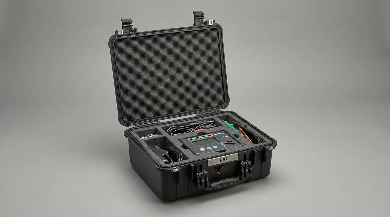
Read the outer case first: look for rupture or distortion of the shell, and watch especially for water staining that would reach the fin field and cause corrosion between fins. Confirm that the seals are intact and match the document, then read the humidity indicator card; if it has changed colour, open the case immediately and check the fins for water marks, dented rows and collapsed pitch.
Check the appearance: verify drawing numbers and quantities against the packing list; inspect fins for collapse, tubes for dents, end seals for impact damage, header ports and bevels for damage, and sleeves and caps for completeness.
Check the state: verify performance test labels and their seals; verify heat-treatment markings where applicable; verify iron-contamination inspection records for stainless parts where required.
Measure straightness: for heat pipes and headers, use a taut line or a surface plate with feeler gauge, record the values and compare against factory data.
Measure fin pitch: sample several rows of a finned bundle and compare against the drawing nominal to determine whether whole rows have collapsed.
For volume orders, incoming inspection of cases and inserts can follow an AQL sampling plan (see custom case acceptance and AQL sampling): appearance defects at general inspection level II with AQL 2.5, and defects affecting protective performance such as missing gasket, misplaced cradle, non-conforming relief cavity or failed latch at AQL 0.65 or under tightened inspection. For fin-field projects, add a dedicated cradle relief check: confirm that the cradle actually leaves clearance in the fin field rather than nominally avoiding it while touching in practice.
The OEM/ODM flow typically runs: requirement clarification (component list, envelope dimensions, weights, fin orientation and pitch, end configuration, transport mode and destination climate), grading and case-splitting plan, insert and cradle design including relief cavities, sample case trial fit with straightness confirmation, test verification including component-specific re-checks, volume production, and delivery with identification. At sample stage, confirm three things in particular: whether handling is smooth, whether the fin field is genuinely unpressurised, and whether long parts retain slight freedom inside the case. JUNZHJIA supports the sample stage with insert drawings, cradle layout recommendations and trial-fit feedback, supplies seals and cradle hardware configured to each heat-pipe diameter, and returns trial-fit records plus packing documents with fin-field clearance checks.
For cases intended for reuse across projects, use a standard shell plus adjustable cradles strategy: the shell and hardware are common while cradle mounting positions are adjusted to component length and diameter. This is especially economical for manufacturers with many heat pipe specifications and scattered batch sizes. Where tooling is involved, evaluate mould amortisation first (see protective case mould cost analysis). When selecting a supplier, also look at insert dimensional consistency and material batch stability so that cradle positions do not vary between batches (see identifying genuine versus counterfeit protective cases).
FAQ
Q: Why is fin collapse irreversible, and how can it be prevented structurally in transit?
A: Fins are thin sheet structures. When force acts perpendicular to the fin plane they first buckle elastically, and once the critical load is exceeded they enter plastic deformation. On unloading the elastic part recovers and the plastic part remains, which is why collapse is irreversible. The domino effect makes it worse: one folded fin presses on its neighbour, producing whole-row collapse, which finally shows up as uneven fin pitch, reduced air-side flow area and higher resistance. There are three structural countermeasures. First, avoid any normal pressure perpendicular to the fin plane, including straps, transverse timber battens and fin-face-to-fin-face stacking. Second, pass load through the stiffer end plate or tubesheet, with a mid-support beam that does not touch the fins and transmits force through the end plate or a dedicated fixture. Third, use soft lateral location instead of normal clamping, so the stops limit transverse movement without applying perpendicular force. Also note that fin edges are sharp and can cut insert material into debris, so use cut-resistant material or an isolation sheet at the contact face.
Q: Why are heat pipes more sensitive to bending than to scratching?
A: Because heat pipe performance depends on the uniformity of internal geometry. A heat pipe normally contains a wick structure, whether grooves, mesh or sintered powder, plus a vapour channel. The working fluid evaporates in the evaporator section, condenses in the condenser section and returns through the wick. This cycle requires that the vapour channel cross-section and the continuity of the wick stay consistent along the whole length. Once the tube bends, the cross-section in the bend region changes and wick continuity may be affected, so isothermality degrades and thermal resistance rises; in severe cases a local heat transport limit appears. None of this is visible externally and only performance testing reveals it. Surface scratching, by contrast, generally affects appearance and coating adhesion rather than internal structure. The governing transport metric for a heat pipe is therefore straightness: derive support spacing from allowable deflection, practically L/1000; use half-round cradles matched to tube diameter; apply no concentrated load at mid-length; and never strap directly around the tube.
Q: How should load be transmitted in a finned tube bundle?
A: The sound approach is end plates carry the load, no fin contact in the middle, and soft lateral location. The end plate, or tubesheet, is the stiffest region of the bundle, so using it as the primary load-bearing point creates a load path of case floor, cradle, end plate, bundle, in which the fins take no part whatsoever. If mid-length support is needed, use a support beam that does not touch the fins, transmitting force through the end plates or a dedicated fixture rather than pressing on fins. Laterally, soft stops limit transverse movement inside the case without applying force perpendicular to the fin plane. A practical way to verify the design is this: with the bundle loaded, push lightly on the side of the fin field with a finger; if it cannot move appreciably, lateral location is working. At the same time, check with a feeler gauge that clearance actually exists between cradle and fin field, which confirms there is no normal pressure. This feeler-gauge check should be a mandatory item after packing.
Q: What problems does a sealed case encounter in air freight or high-altitude transfer?
A: The main problem is the internal-external pressure differential. In an air freight hold or at altitude, external pressure drops significantly while the interior remains at the sealed pressure, so the differential acts on the walls and gasket. It shows up in three ways: the gasket is forced into the case and the closure face deforms; the side walls or lid bulge; and on opening, residual differential makes the lid hard to open or even tears the gasket. For a long case the differential also creates larger structural stress along the length. The answer is a pressure equalisation valve, which allows gas to exchange slowly and equalise the differential while its structure blocks liquid water and dust, solving the problem without sacrificing the protection level. When selecting one, confirm that valve flow rate matches case volume, since a larger volume needs faster equalisation. Multi-climate sea freight, for example from a cold zone to a tropical one, also creates a differential in the opposite direction, so pressure equalisation valves are valuable on ocean freight too.
Q: What special requirements does a heat pipe case have for humidity control?
A: Requirements are stricter than for general machinery for three reasons. First, fin spacing is small, so water is held between fins by capillary action and drains poorly, creating a persistently humid environment; for aluminium fins this accelerates corrosion, and for copper tube with aluminium fins it can drive galvanic corrosion with aluminium as the anode. Second, header ports, bevels and sealing faces corrode readily, and corrosion products affect later welding and sealing. Third, dissimilar metals in the same case create galvanic corrosion, so copper, aluminium, stainless steel and carbon steel need isolation. In practice the combination is sealing plus desiccant plus a humidity indicator card: desiccant quantity is set by free volume, sealing level, transit duration and destination climate, with a practical value of 20 to 50 g of silica gel per 20 L of free volume and the upper end for ocean freight or humid destinations; the indicator card shows whether the protection has expired or moisture has entered. In addition, a sealed case must use closed-cell insert materials, because open-cell foam and felt absorb moisture and then act as an internal water source.
Q: Which tests should a heat pipe or heat-transfer element case undergo, and what must be re-checked afterwards?
A: Use a two-layer structure of transport testing plus component-specific re-checks. For transport testing, three families of reference are common: the GB/T 4857 series covering vibration, impact, stacking and drop methods; the ISTA series organising sequences around the distribution environment for export and intermodal routes; and ASTM D4169 using a distribution cycle plus assurance level approach for high-value large items. For cargo whose performance depends on geometric precision, complete at least vibration, impact and stacking, and add bending verification for long parts. Component-specific re-checks should cover at least four items: measure the straightness of heat pipes and headers after testing and compare with pre-test data; inspect the fin field for newly collapsed rows; check whether end sleeves have shifted and whether the seal area shows impact marks; and check whether vibration has generated new debris in the case or loosened any plugs. Where MIL-STD-810H is cited as an environmental test method reference, state that it is not a military certification and does not constitute product certification.
Q: Why must plate heat exchanger plates be stood on edge rather than laid flat and stacked?
A: Because the geometric precision of the plate is its performance. A plate is a thin corrugated metal sheet whose corrugation geometry determines the channel shape and heat transfer characteristics. When plates are laid flat and stacked, they carry self-weight plus the pressure of the plates above, and the contact areas see sustained pressure. The corrugation peaks of adjacent plates press against each other, which readily produces local deformation and corrugation misalignment, affecting the channel shape after assembly and the alignment of the gasket groove. Stacking flat also causes sliding friction between plates that scratches the surface, and on stainless plates a scratch becomes a corrosion initiation site. Standing on edge lets the load pass through the plate edges so the plate face carries almost no pressure, and it simplifies lifting and visual inspection. Three points then apply: separate plates with soft dividers and never let metal faces touch; restrain assembled plate pairs as a unit so they cannot come apart inside the case; and store gaskets separately so they are not compressively deformed.
Q: When must heat pipes and heat-transfer elements be shipped in separate cases?
A: Mainly according to geometric fragility and the weight range. If one consignment contains finned tube bundles, which are H1 and cannot take any compression, together with headers or frames at H4 that can carry load, mixed loading means the weight and movement of the structural parts will directly crush the fins, so the cases must be split. Similarly, mixing long heat pipes at H2 with small precision items means the ends of the long parts can strike the small items under vibration, so those should be separated too. The criterion reduces to three questions: is there a load-bearing mismatch, in other words would one component's self-weight exceed another's compressive capacity; is there a stiffness mismatch, in other words would hard items abrade soft surfaces under vibration; and do the acceptance methods differ, since fin-field work needs feeler-gauge or pitch sampling while long parts need straightness measurement, which is hard to zone in a mixed case. After splitting, supply a case-splitting list with drawing-number identification and mark the grade and stacking direction on each case, so the carrier can allocate cases properly and site acceptance can proceed case by case.
Q: What else should export projects consider for heat pipe and heat-transfer element packaging?
A: Three categories beyond protective performance. The first is phytosanitary requirements for wood packaging: many countries require fumigation or heat treatment of solid wood packaging, and using timber support blocks or timber pallets adds processing steps and waiting time; a rigid plastic case with fumigation-free pallets simplifies the flow, and it is worth noting that timber support blocks also shed debris and cause contamination, which is unsuitable for fins and passages in any case. The second is documentation and compliance: export projects usually need a packing list, component numbers and identification, and where a heat pipe or heat exchanger serves as a pressure part, the manufacturing and inspection documents for the component itself should accompany the shipment, with a clear statement that the case is transport packaging and does not replace the component design and manufacturing requirements. The third is climate adaptability: for ocean freight and humid destinations aim for IP67 with a pressure equalisation valve and sufficient desiccant, and consider the stability of insert materials at high temperature and humidity, since a softened cradle would leave long parts unsupported. Write these requirements into the technical agreement item by item and complete sampling before dispatch.
Conclusion & Related Reading
The design logic of a heat pipe and heat-transfer element case can be summarised in four lines: carry load at the ends instead of on the fins, control the deflection of long parts with multiple cradles, replace normal clamping with soft lateral location, and block moisture and galvanic corrosion with sealing plus desiccant. Add arrival re-checks of straightness and fin pitch, transport test verification and zoned case splitting, and the arrival condition of heat pipes and heat-transfer elements moves from luck to records.
Two boundaries should be stated. First, this class of case is an outer transport packaging container. It does not participate in the design or manufacture of the heat pipe or heat exchanger itself and is not a pressure part or a vacuum component. Where a component serves as a pressure part, its own design, manufacture and inspection must follow applicable regulations and standards, including GB/T 150 for pressure vessel design and TSG 21 for fixed pressure vessels, and where it is supplied with a boiler system, awareness of GB/T 16507 for boilers applies; a case cannot substitute for those requirements. Second, MIL-STD-810H serves only as an environmental test method reference and is not a military certification; where fire requirements or air freight apply, UL94 flame-retardant evidence can be required for the insert material.
JUNZHJIA (Kexin New Materials (Guangdong) Co., Ltd.) supplies heat pipe and heat-transfer element cases to heat pipe manufacturers, heat exchanger suppliers, waste-heat recovery contractors and export traders, with custom inserts, multiple cradles, relief cavity design, OEM/ODM programmes and volume production, and can issue case-splitting plans, per-building-block packing specifications with cradle-layout drawings, relief-cavity notes, seal lists and arrival re-check records for heat-transfer elements.
Related Reading