

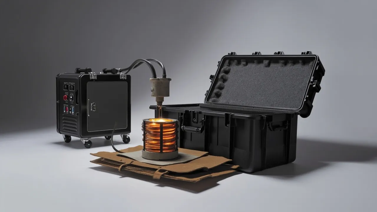
Spare-part packaging for induction melting furnaces, including medium-frequency and mains-frequency units, has a characteristic that is widely underestimated: both the induction coil and the crucible look robust while being extremely sensitive to vibration and moisture. The coil itself is wound from copper tube, and the position accuracy of turn insulation, water-circuit fittings and terminals determines whether the unit can be energised and cooled correctly after installation. The crucible is a brittle refractory or graphite body whose impact tolerance is far lower than its appearance suggests. The conclusion is straightforward: treat the coil as precision electrical equipment, treat the crucible as a highly brittle moisture-sensitive item, and if the two must share a case, isolate them physically and apply separate vibration and moisture strategies.
This article is written for induction furnace manufacturers, foundry equipment departments, refractory lining crews and equipment traders. It covers packaging methods for coils and crucibles, transport acceleration budgeting and vibration class selection, the logic behind liner support forms, insulation resistance and moisture re-test workflows, and an arrival acceptance checklist. Figures quoted are typical industry values and experience ranges; the actual scheme must follow your furnace model, coil specification, transport mode and contractual technical specification.
Table of Contents
- Why Induction Melting Spares Cannot Ship as Ordinary Equipment
- Induction Coils: Turn Insulation, Water Circuits and Terminal Protection
- Crucibles: Brittleness Differences Between Graphite, Silicon Carbide and Alumina
- Transport Acceleration Budget and Vibration Class Selection
- Liner Design: Multi-Point Compliant Support and Turn Spacing Location
- Insulation Resistance: The First Item to Re-Test After Transport
- Controlling Short-Circuit and Static Electricity Risks
- Cleanliness, Oil and Dust Control Requirements
- Test References: ISTA, GB/T 4857 and MIL-STD-810H
- Case Marking and Travelling Technical Documents
- Arrival Acceptance, On-Site Storage and Re-Test Records
- Custom Liners and OEM Delivery Workflow
- Frequently Asked Questions
- Conclusion and Related Reading
Why Induction Melting Spares Cannot Ship as Ordinary Equipment
Induction furnace spares differ fundamentally from conventional mechanical components. Ordinary parts have clear load paths and generous stiffness margins, so packaging aims mainly to prevent knocks. The two core components of an induction furnace do not meet that premise.
The induction coil is a functional conductor. Its electrical performance depends on uniform turn spacing, the integrity of inter-turn insulation, and an unobstructed, leak-free water circuit. Copper tube has modest yield strength, so local bending changes not only turn spacing and therefore inductance but also distorts the tube cross-section at the bend, which affects flow distribution in the cooling circuit. The more subtle risk is insulation damage: a local indentation may leave no visible surface break yet reduce dielectric strength, becoming an initiation point for breakdown under high-frequency voltage.
The crucible is a functional vessel. It withstands molten metal at high temperature along with thermal shock and mechanical erosion, and it does so through structural integrity free of cracks. Graphite crucibles are relatively strong but still distinctly brittle. Silicon carbide and alumina (corundum) crucibles offer good thermal shock resistance but limited tolerance of impact and local compression. Quartz and high-silica crucibles have excellent thermal shock resistance yet the most extreme brittleness of all. A single drop or local squeeze in transit may only create internal micro-cracks, which then propagate into through-wall failure when the unit is first heated, at which point the risk is a molten metal breakthrough.
The packaging goals should therefore be stated precisely: the coil must retain unchanged geometry, undamaged insulation and unobstructed water passages, while the crucible must come through without hidden cracks, without moisture uptake and without local point loading. Three goals imply three different sets of measures, which is what the sections below unpack.
A further difference is frequently overlooked: the storage lead time for spares. Foundry spares are often purchased months ahead and stored in a corner of the workshop or a semi-open store, where humidity is high, dust is present and metal swarf may be nearby. A coil stored for a long period in a dusty, metal-particle-bearing environment loses surface insulation performance, and a crucible in a damp environment absorbs moisture that directly affects first heat-up. Packaging design must therefore cover transport plus storage as one combined duty, not just the logistics leg.
Induction Coils: Turn Insulation, Water Circuits and Terminal Protection
A coil or inductor assembly typically comprises the wound copper tube coil body, inter-turn spacers or insulating pads, water-circuit fittings for supply and return, terminals connecting to the busbar, an external insulating coating, and in some furnace types magnetic yokes and mounting brackets. Each element has a different weakness.
The coil body is vulnerable in turn spacing and roundness. In the free state a coil retains some elastic recovery, but if it is rigidly clamped and then subjected to vibration and temperature change, turn spacing shifts locally. Packaging must therefore support rather than clamp, with support points distributed as uniformly as possible around the circumference.
Inter-turn spacers and insulating pads are vulnerable to loss and displacement. If these small items go missing during on-site reassembly they cause inter-turn short circuits, so they should travel in their own small box with their quantity listed separately on the packing list.
Water-circuit fittings are vulnerable in thread and sealing face. Fittings are usually copper or steel threaded parts, and the two transport risks are thread deformation from impact and internal blockage by foreign matter or packaging debris. Fit protective caps, insert a clean plug inside the cap to keep foreign matter out, and ensure fittings are never the lowest point in the case where liquid could collect.
Terminals are vulnerable in surface plating and flatness. Terminals must make reliable contact with the busbar, and once the contact face is scratched or oxidised the contact resistance rises and generates heat. Fit soft protective sleeves and reserve independent space in the liner so terminals touch nothing else.
External insulating coating is vulnerable to scratching and contamination. The coating provides insulation to earth and moisture resistance, and any scratch can become the starting point for surface tracking. Contact surfaces should use a lint-free, halogen-free soft facing.
From a packaging engineering perspective, the most suitable support form for a coil is multi-point compliant support: several support blocks distributed uniformly around the circumference, each making area contact rather than point contact with the coil surface, in a medium-hardness foam or rubber that both locates the coil and damps vibration. For large-diameter coils, add radially compliant limiters so that inertial displacement under shock stays bounded.
One detail deserves emphasis: the coil must not contact other metal parts directly. Beyond mechanical impact, dissimilar metal contact in a damp environment creates galvanic corrosion, and local pitting can appear on copper surfaces. Provide an independent non-metallic isolating layer between the coil and any metal component.
Crucibles: Brittleness Differences Between Graphite, Silicon Carbide and Alumina
Crucible packaging must be differentiated by material, because mechanical and moisture behaviour differ widely.
Graphite crucibles, including clay-bonded graphite types, conduct heat quickly and resist thermal shock well, but flexural strength depends strongly on the binder phase, and edges plus the bottom corner are stress concentrations. Graphite itself does not absorb moisture, but the clay or resin binder can, and strength falls after prolonged damp storage. The packaging priority is impact resistance and moisture control together.
Silicon carbide crucibles are hard, wear resistant and excellent in thermal shock resistance, but markedly brittle with high notch sensitivity. Micro-cracks created by local compression propagate under thermal cycling. The packaging priority is eliminating point loading so that every contact is an area contact.
Alumina and high-alumina crucibles resist high temperature and chemical attack well but have relatively weaker thermal shock resistance, so both sudden temperature change and mechanical impact can cause cracking. The priority is impact protection and temperature control, avoiding handling at temperature extremes.
Quartz and high-silica crucibles have the best thermal shock resistance but the most extreme brittleness, with the lowest tolerance of impact and local stress. They normally require individual packaging and individual cushioning, and should not share a case with any heavy component.
The following matrix summarises the material-to-packaging relationship:
| Crucible material | Principal advantage | Transport weakness | Moisture tendency | Packaging priority |
|---|---|---|---|---|
| --- | --- | --- | --- | --- |
| Graphite | Fast heat conduction, good thermal shock | Edge and bottom corner cracking | Binder phase may absorb | Area-contact cradle plus barrier film plus desiccant |
| Silicon carbide | Wear resistant, excellent thermal shock | Notch sensitive, point load cracking | Low | Eliminate point loads, full-perimeter area contact |
| Alumina (corundum) | High temperature, corrosion resistant | Moderate thermal shock, impact cracking | Low to medium | Cushioning plus temperature control plus independent support |
| Quartz and high silica | Outstanding thermal shock | Extremely brittle, easily fractured | Low | Individual packaging, individual cushioning, no stacking load |
The moisture question for crucibles deserves separate treatment. Densely sintered corundum crucibles have very low water absorption, but high-refractoriness monolithic crucibles, ramming-mix formed crucibles and clay-bonded graphite crucibles can all absorb moisture from ambient air. The consequence is violent vaporisation during first heat-up, causing cracking or bursting. Crucible packaging should therefore include a barrier layer and a metered desiccant charge, and moisture content should be measured against the agreed method after arrival rather than judged visually.
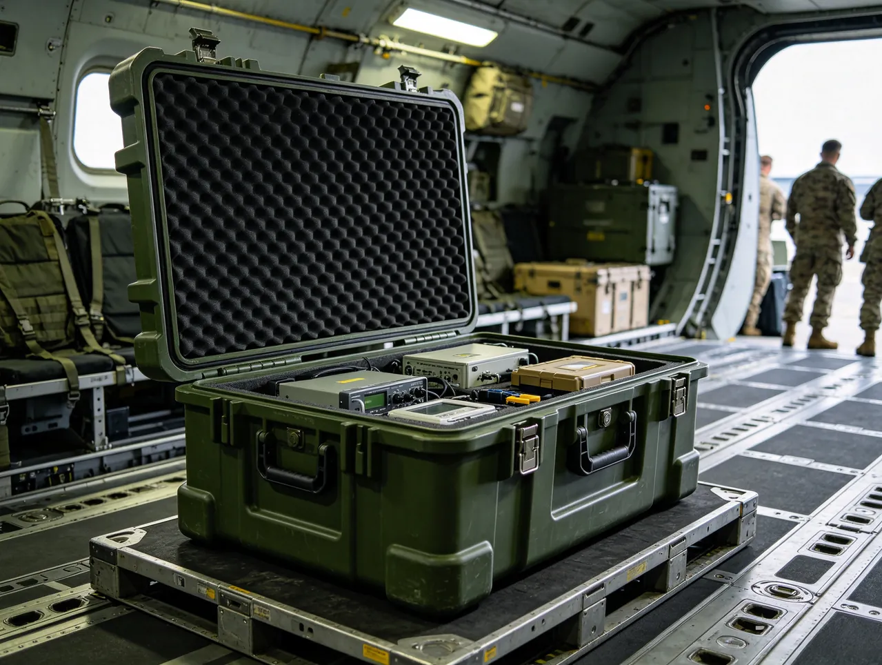
Support for a crucible should use a cradle conforming to the base contour, with the contact surface being continuous rather than a set of raised points. For large-diameter crucibles, add compliant lateral restraint to prevent transverse sway into the case wall during transport. A crucible must never be inverted or laid on its side unless the manufacturer explicitly permits it.
Transport Acceleration Budget and Vibration Class Selection
Vibration design begins with knowing how much vibration must be resisted. In practice an acceleration budget is established from the transport mode, and cushioning material and support form follow from it, rather than the cushion being chosen by habit.
| Transport stage | Principal excitation | Typical acceleration (experience range) | Most exposed components |
|---|---|---|---|
| --- | --- | --- | --- |
| Manual handling and loading | Drop shock | Several to more than ten times gravitational acceleration | Crucible, terminals |
| Road, good surface | Sustained vibration | Below one times gravitational acceleration | Coil turn spacing |
| Road, poor surface | Vibration plus shock | Several times gravitational acceleration | Crucible, insulation coating |
| Rail marshalling | Longitudinal shock | Several times gravitational acceleration | Axial coil displacement |
| Sea freight | Low-frequency roll and slam | Below one times gravitational acceleration, large displacement | Overall restraint, stacking |
| Air freight | Pressure change plus handling shock | Several times gravitational acceleration | Gaskets, water circuit |
Three vibration classes follow:
Class A, basic: suitable for short-distance transport on good roads. The liner mainly locates the part, with medium-density foam and priority on controlling displacement.
Class B, reinforced: suitable for intermodal transport or poor road surfaces. The liner uses a composite build, coils use multi-point compliant support, crucibles use full-perimeter area-contact cradles, and an independent cushioning layer is included in the case.
Class C, precision: suitable for high-value coils, large-diameter crucibles, air freight or multiple transfers. Beyond class B measures, add an inner barrier bag and independent isolation mounts, and use shock recorders on the first article for measurement.
Note that a higher vibration class does not mean thicker foam. An excessively thick cushion increases the free travel available to the component, so under shock it accelerates further and strikes the liner or case wall as a secondary impact. The correct order is to limit displacement first and then control acceleration. The general approach to cushioning structures is covered in design and selection of cushion liner cases.
Liner Design: Multi-Point Compliant Support and Turn Spacing Location
The liner must do four things: locate position, fix attitude, define clearance and absorb shock. Applied to induction furnace spares, this breaks into the following steps.
Step one, fix the datum. A coil normally uses the plane of the terminal or the flange mounting face as the datum; a crucible uses its bottom plane. Once the datum is fixed, all other locations derive from it, avoiding conflicting datums.
Step two, divide the cavities. Coil, crucible, water-circuit accessories and fasteners each get an independent cavity, separated by rigid dividers that carry their own support. A divider between coil and crucible is mandatory, because the crucible is heavier and would crush the coil if it tipped.
Step three, select support forms. Coils use multi-point compliant support, crucibles use full-perimeter area-contact cradles, accessories use small contoured cavities. Every surface contacting a component should be an area contact, never a line or point.
Step four, set clearances. There should be a controlled clearance between component and liner. Too small and thermal change plus vibration causes compression; too large and the component travels and strikes. Clearance values should be derived from component thermal expansion and transport acceleration.
Step five, leave a removal path. The coil must extract without interference from the wall or divider, and the crucible must lift vertically rather than being dragged diagonally.
For liner material comparison, the following reasoning applies:
| Liner material | Compression behaviour | Suitable location | Caution |
|---|---|---|---|
| --- | --- | --- | --- |
| EVA foam | Good recovery, easy to machine | Coil compliant supports, contoured cavities | Softens in hot environments |
| PE foam | Harder, creep resistant | Load-bearing cradles, dividers | Limited cushioning |
| PU foam | Can be poured in place | Highly irregular outlines | Density and cure must be controlled |
| Rubber and elastomer blocks | Good damping | Isolation mounts, limiters | Confirm compatibility with copper |
| Engineered timber | High stiffness, low cost | Base support boards | Export may require quarantine treatment |
For a comparison of compression set and recovery behaviour across foam types, see protective case foam material comparison.
Insulation Resistance: The First Item to Re-Test After Transport
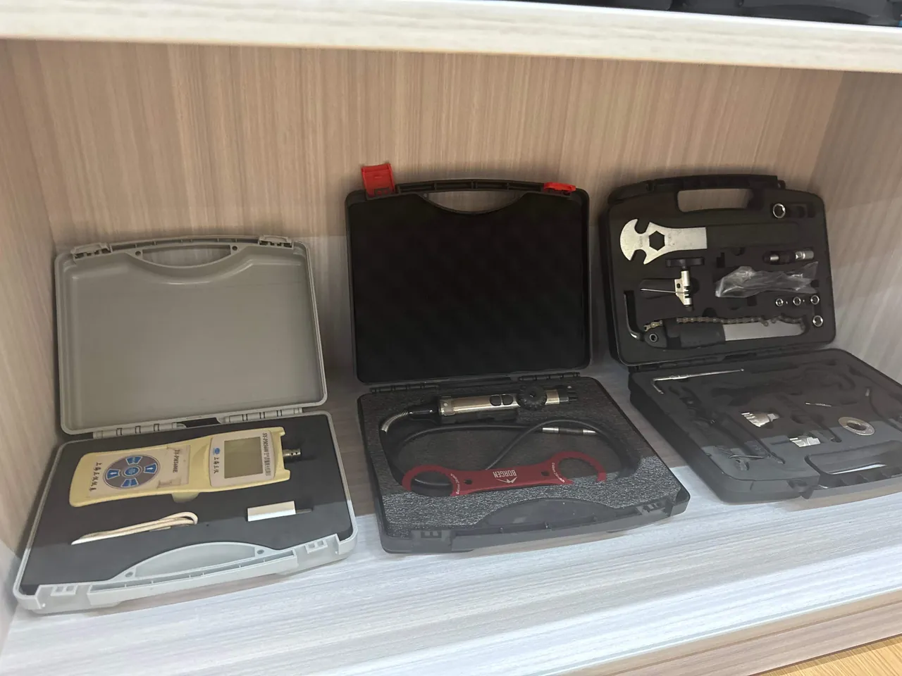
Because the coil is an electrical functional component, re-testing insulation performance is the first acceptance gate after transport and storage, ahead of appearance inspection. The reason is simple: insulation degradation usually leaves no external trace, yet once the furnace is energised it can cause breakdown or an earth fault.
The recommended sequence is as follows:
- Appearance and cleanliness check. Confirm there is no metal swarf, oil or packaging debris on the coil surface. Clean by blowing first and wiping second, so that particles are not pushed into insulation gaps.
- Insulation resistance measurement. Measure at the test voltage and acceptance value specified by the manufacturer, in a dry state, and record ambient temperature and humidity. Confirm the water circuit is drained and fittings are dry before measuring.
- Turn and continuity checks. Confirm the coil conducts normally, that there is no inter-turn short, and that terminals connect reliably to the coil.
- Water circuit check. Verify flow rate and pressure drop with water flowing, confirming no blockage and no leakage. Any plug or cap used in packaging must be fully removed first.
- Record and archive. Record measured values, ambient conditions, instrument and operator as a baseline for future comparison.
One caution matters here: measured values should be interpreted together with ambient humidity. The same coil may read noticeably lower in a damp environment than a dry one, which is physics rather than a defect. Where the manufacturer recommends it, apply a drying step before measurement, or measure under controlled temperature and humidity. If the reading is below the acceptance value, dry and re-measure rather than declaring the part scrap.
For spares held in long storage, establish a periodic re-test regime: for coils stored beyond three months, re-measure insulation resistance quarterly and record the trend. A downward trend is more informative than a single low reading, because it usually points to seal failure or inadequate environmental humidity control.
Where third-party confirmation is required, the logic in protective case shipment acceptance sampling (AQL) can be applied to sample the packaging condition and unpacking results, recording packaging conformity and component conformity separately so that responsibility is clearly attributed.
Controlling Short-Circuit and Static Electricity Risks
Induction furnace operations carry inherent electrical risk, and packaging that is not controlled can carry that risk forward to the site. Three measures are mandatory.
First, prevent metal foreign objects from entering the case. Metal swarf, screws or weld spatter falling into a case and touching the coil can bridge turns. Measures include cleaning the packing area before work, using non-metallic tools, avoiding liner designs with detachable metal parts, and performing a visual confirmation of the case interior after packing.
Second, control static electricity. In dry conditions, friction between foam and component can accumulate static charge. For a coil with an insulating coating, electrostatic discharge can damage that coating. Use conductive or static-dissipative materials on contact surfaces between liner and component, or add a static-dissipative facing inside the case. Material selection is covered in design essentials for ESD shielding cases.
Third, define the boundary between earthing and insulation. Packaging does not require earthing, but the case interior and exterior should not form an unintended conductive path, for example by running a metal strap across an insulating surface. Where metal strapping is necessary, place an insulating pad between strap and component and confirm the strap cannot abrade the insulating coating under vibration.
In addition, if the case also contains yokes, busbars or other conductive metal parts, keep adequate separation from the coil and restrain them separately. Conductive parts must never rest on an insulating component under any circumstances.
Cleanliness, Oil and Dust Control Requirements
In auxiliary equipment and foundry environments, dust and oil are normal conditions. For induction furnace spares, cleanliness is a functional requirement rather than an appearance concern.
Dust mainly degrades insulating surfaces and blocks water fittings. Metal-bearing dust, such as cast iron dust and grinding swarf, is particularly harmful because under damp conditions it can form a conductive path. Controls include blowing the component clean before packing, wrapping in barrier film, reducing internal humidity with desiccant, and cleaning before insulation re-test on arrival.
Oil alters the surface behaviour of insulating materials and gives dust a substrate to adhere to. If a spare has been stored in an oily environment, clean it and apply the manufacturer's recommended drying before packing. Liners should be oil resistant, or an oil-resistant layer added at contact surfaces.
Packaging materials themselves can be a contamination source. Low-grade foam sheds debris, paper packaging may contain acidic substances, and some plastic films release plasticisers at elevated temperature. State cleanliness and composition limits for packaging materials in the technical specification, so that tighter packaging does not paradoxically increase contamination.
Where cleanliness requirements are high, an inner barrier bag plus desiccant isolates the component from the packaging materials. This structure addresses moisture and contamination at the same time and is the recommended configuration for large-diameter coils and large crucibles.
Test References: ISTA, GB/T 4857 and MIL-STD-810H
Basing packaging verification on citable test references is what turns a claim of reliability into something that can be accepted. The common references and their applicability are as follows.
- ISTA transport test procedures: selected by distribution mode, including parcel, LTL, truckload and intermodal. Where combined vibration and drop effects need evaluation for coil packaging, they are practical to apply.
- GB/T 4857 series: basic tests for transport packages, covering stacking, vibration, impact and drop, widely used in domestic projects and well correlated with domestic transport conditions.
- ASTM D4169: organises test sequences around a distribution cycle, suited to export projects.
- MIL-STD-810H: environmental test methods applicable to vibration, shock, humidity and temperature, used as an environmental suitability verification basis. Note that this is a method reference and not a military certification; cite the specific method number, severity level and acceptance criteria.
- GB/T 2423 series: environmental testing for electrical and electronic products, suitable for qualifying the coil assembly separately for damp heat and vibration.
For coils, write the acceptance criteria in quantitative form: no damage to coil appearance after test, turn spacing variation within the specified limit, insulation resistance not below the specified value, and water-circuit flow capacity not below the specified value. Only numerical criteria make a test report usable for acceptance.
For crucibles, acceptance criteria should include both appearance (no cracks, no corner loss) and moisture content (not exceeding the specified value). Because hidden damage in a crucible cannot be fully identified visually, moisture content often becomes the more reliable indicator.
Case Marking and Travelling Technical Documents
Marking exists so that the site can handle and unpack correctly without a designer present. At minimum it should include the following.
Handling marks: this way up, keep dry, do not roll, stacking limit, do not use hooks. Crucible cases should also carry do-not-invert and handle-with-care marks.
Centre-of-gravity and lifting marks: mark the centre of gravity and the lifting points, and prohibit using the component itself as a lifting attachment point.
Zone marks: label each internal cavity at the corresponding position on the outer case so contents are not mixed after opening.
Traceability marks: case number, batch number, item number, production date and QR code, so that items can be reconciled against the furnace equipment train.
Travelling technical documents should include the packing list with item number, quantity, material, unit weight and key parameters such as turns or capacity; the liner layout and repacking instructions; water-fitting protection notes; the desiccant dosing record and humidity indication note; recommended insulation re-test values and measurement conditions; and copies of material and inspection documents as needed. Export projects should also carry wood packaging treatment marking evidence where timber is used.
Consistency between documents and physical contents matters equally. Reconcile the packing list item by item and sign it off after packing, so that a quantity discrepancy discovered at site can be traced.
Arrival Acceptance, On-Site Storage and Re-Test Records
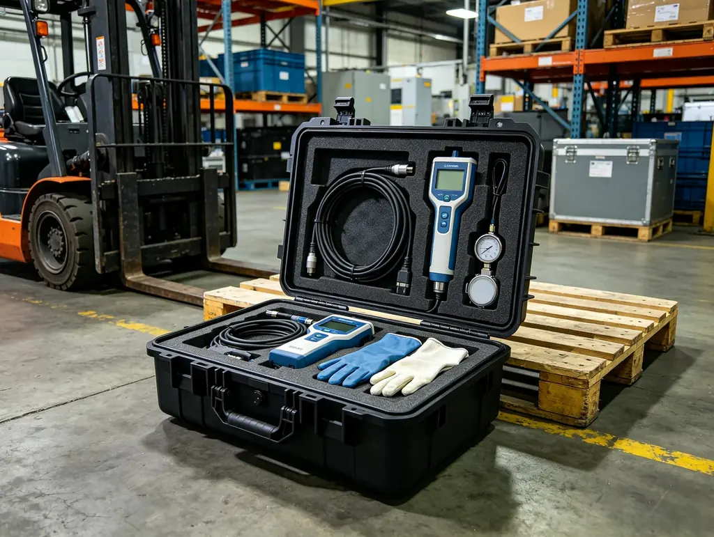
Arrival acceptance should produce an archivable record, as shown below:
| Check item | How to check | Pass condition | Follow-up when it fails |
|---|---|---|---|
| --- | --- | --- | --- |
| Case body | Visual inspection | No puncture, no distortion, gaskets intact | Photograph, then open the case entirely |
| Humidity card | Read the indicator | Below the colour-change threshold | Re-test every moisture-sensitive item |
| Coil appearance | Visual and tactile | No indentations, scratches or metal swarf | Clean, then re-test insulation |
| Turn spacing | Sampling measurement | Deviation from dispatch record within tolerance | Assess rework if exceeded |
| Insulation resistance | Instrument measurement | Not below the specified value | Dry and re-measure |
| Water circuit flow | Flow test | Normal flow and pressure drop, no leakage | Investigate blockage and fitting damage |
| Crucible appearance | Visual and tap test | No cracks, no corner loss, clear ring | Batch concession assessment |
| Crucible moisture | Sampling test | Not exceeding the specified value | Dry and re-measure |
| Liner condition | Visual | No displacement, collapse or debris | Check whether components contacted |
| Documentation | Reconciliation | Packing list matches contents | Release to store only after completion |
On-site storage should follow four principles: raised off the ground, clear of walls, away from dust and oil sources, and stacked by marking without exceeding the limit. Neither coils nor crucibles should remain long in open areas of a workshop; where possible store them in a relatively sealed, humidity-controlled store and read the humidity indicator or re-test insulation resistance periodically.
Records during storage matter just as much. Log the storage start date, store temperature and humidity readings, re-test dates and results. These records are decisive evidence in any later quality dispute and also provide the data needed to improve the packaging scheme.
Custom Liners and OEM Delivery Workflow
Induction furnace models are numerous, and coil diameter, turn count, terminal position and orientation, and crucible size vary widely, so standard case types rarely cover the range and customisation levels are high. A five-step workflow is recommended.
Step one, collect data. Provide coil outer diameter, height, turn count, terminal position and orientation, water fitting size and position, and unit weight; crucible outer diameter, height, material and unit weight; plus transport mode, storage duration and destination climate.
Step two, design the solution. Issue the case structure, liner cavity division, support forms, sealing and drying scheme, and the marking and document list. State explicitly which components must ship in separate cases.
Step three, verify the first article. Build a first article and run loading verification, adding transport testing or shock recorders where required.
Step four, volume production and traceability. Produce by batch number and retain key process records.
Step five, site support. Provide repacking drawings, an acceptance form template and a recommended storage note.
Production of the liner assemblies and case bodies for this family is carried out by Kexin New Materials (Guangdong) Co., Ltd., which tailors liner cavity geometry and gasket specifications to the induction furnace model, accepts OEM/ODM work and serves customers through wholesale, agency and direct global supply channels. Where acceptance is required, the relevant inspection and material documents can be issued under contract. For buyers purchasing coils and crucibles together, settle the case-splitting strategy at the design stage so that the site is not improvising after arrival. Where a project also involves protection of hot-working components, the practices in heat treatment equipment component cases and foundry ladle transport cases are useful references.
Frequently Asked Questions
Q: Can induction coils and crucibles be shipped in the same case?
A: Sharing one case body is acceptable in principle, but sharing one cavity is not; a rigid divider is the minimum requirement. There are two reasons. First, weight and brittleness differ greatly. A crucible is usually much heavier than a coil, so if its restraint fails and it tips, it will crush the coil directly. Second, environmental needs differ. The crucible may need a barrier film and desiccant to control moisture content, while the coil needs cleanliness and static control, and in a shared humidity volume the desiccant is consumed preferentially by the crucible side. If co-packing is unavoidable, use a rigid divider with its own independent support to separate the two completely, give each its own barrier layer and desiccant, place the crucible on the side aligned with the case load-bearing structure on a full-perimeter area-contact cradle, and place the coil on the other side with multi-point compliant support. For large-diameter crucibles or high-value coils, separate cases are still recommended, because the cost increment is far below the cost of on-site rework and schedule loss.
Q: If coil insulation resistance reads low after transport, does that mean the coil is defective?
A: Not necessarily; the reading must be interpreted against the measurement environment. Insulation resistance is highly sensitive to humidity, and the same coil can read appreciably lower in a damp environment than a dry one, which is physics rather than a defect. The proper approach is to confirm the measurement conditions first: ambient temperature and relative humidity, test voltage and measurement duration must match the manufacturer's specification. If conditions do not match, apply the specified drying step or re-measure under controlled temperature and humidity. If the reading is still low after that, investigate surface contamination by dust, oil or metal swarf, residual water in the water fittings, and any indentation or scratch in the insulation coating caused in transit. Work from cleaning and drying outward to coating inspection, rather than declaring the part scrap immediately. For spares held long term, establish periodic re-testing and trend records, since a downward trend is more informative than a single low value.
Q: What should be checked first on a crucible after transport?
A: Appearance and moisture content, and both are essential. For appearance, check for corner loss, cracks including hairline cracks, damage at the bottom corner, and any abnormal spots or discolouration. Tap the crucible body lightly: a clear ring usually indicates structural integrity, while a dull sound suggests a possible internal defect requiring further confirmation. For moisture content, note that hidden damage in a crucible cannot be fully identified visually, so moisture testing is often more reliable than appearance, particularly for clay-bonded graphite and monolithic types. If moisture content exceeds the limit, apply the manufacturer's recommended drying and re-test rather than putting the crucible straight into service, because violent vaporisation during first heat-up can cause cracking. Also confirm the crucible has not shifted inside the case, since displacement usually means restraint failed and the crucible may have experienced shock even if it looks undamaged. Where any doubt remains, record the finding, photograph the condition and consult the crucible manufacturer before the first heat-up rather than resolving the question during commissioning.
Q: Is thicker liner foam always better for vibration control?
A: No. Excessively thick cushioning has two contrary effects. First, it increases the free travel available to the component, so under shock the component accelerates over a longer distance and then strikes the liner or case wall as a secondary impact. Second, thick soft foam compresses permanently under sustained static load, so after long storage the support fails, the component settles and contacts neighbouring parts. The correct sequence is to limit displacement first and then control acceleration: use the liner to bound the component's travel within a sensible range, then apply a cushion of appropriate thickness to bring transmitted acceleration down to an acceptable level. Thickness and hardness should be calculated or tested from component weight, contact area and expected acceleration, not accumulated from habit. For a coil, where geometric precision is critical, displacement control usually matters more than absolute cushioning; for a brittle crucible, both must be addressed together. Where the two requirements conflict, resolve the conflict with geometry, using positive stops and shaped cradles to bound travel, rather than by adding more foam everywhere.
Q: Must transport testing always include a drop test?
A: No, testing should follow the actual logistics chain and remain practicable. A drop test is reasonably representative for small, single-item, repeatable packages. For large, heavy or high-value packages, a full drop test is often neither safe nor economic to perform. Alternatives include local structural load testing, supplementary simulation, testing a representative scaled item, or installing shock recorders on the first production shipment and reading back the data. For induction furnace spares, first-article measurement with shock recorders is frequently the most valuable option, because it records the actual acceleration and shock events along the real chain and directly informs whether liners need strengthening or support points need moving. Whichever route is chosen, write the method, conditions and acceptance criteria into the technical specification, otherwise the resulting report will not support acceptance. Where the first article is instrumented, keep the recorded data with the delivery documents so later batches can be compared against a real baseline rather than an assumption.
Q: Why is direct contact between the coil and other metal parts prohibited?
A: There are two layers of reason. Mechanically, metal-to-metal contact transmits vibration and shock almost without attenuation, and the contact points concentrate stress, easily producing indentations on the copper tube surface. Copper tube wall thickness is limited, so an indentation locally reduces the section and changes turn spacing. Chemically, copper in contact with steel or aluminium in a damp environment forms a galvanic couple, and the copper surface can suffer pitting that degrades both conduction and heat dissipation. Packaging should therefore place an independent non-metallic isolating layer between the coil and any metal component, and that layer should be lint-free, halogen-free and oil resistant so it does not introduce a new contamination source. If metal accessories must travel in the same case, give them their own cavity rather than separating them from the coil with a simple foam layer. The isolating layer itself must also be inspected for wear at each unpacking, since a damaged layer no longer performs either function.
Q: What maintenance should be performed when spares are stored for more than three months?
A: A periodic maintenance routine is recommended. First, read or inspect the humidity indicator card, and if the threshold is reached, replace the desiccant and reseal the case. Second, re-test coil insulation resistance on the prescribed cycle and record it, watching the trend rather than a single value. Third, inspect the liner for displacement or collapse, especially beneath coil support points and the crucible cradle, since foam creeps under long-term static load. Fourth, check the case gaskets for ageing and embedded grit. Fifth, confirm no new contamination source has appeared nearby, such as a newly installed grinding station or an oil store. Record every maintenance action and its date to build a traceable maintenance log. For projects in high-humidity coastal locations, shorten all of these intervals appropriately. Assign one named person to own the log, so that the maintenance history stays continuous even when shift teams change. Treat any repeated finding, such as the same liner settling twice, as a design signal rather than a one-off incident.
Q: Does a high case ingress protection rating satisfy on-site storage requirements by itself?
A: No, they are not equivalent. Ingress protection describes dust and water resistance, while the main threats during long on-site storage include the breathing effect caused by temperature cycling, ground damp, dust and oil contamination, and stacking pressure. A case with a high protection rating stored in an open yard will still accumulate internal moisture gradually through temperature cycling. On-site storage must therefore also satisfy: raised off the ground, clear of walls, no standing water on the lid, within the stacking limit, and away from dust and oil sources. For long storage, fit a humidity indicator inside and provide an inspection window or an external label showing its position, so the condition can be read without opening. Where humidity sensitivity is extreme, an inner barrier bag with metered desiccant reduces the controlled volume from the whole case to the bag interior, markedly improving reliability and reducing desiccant consumption. Whatever the structure, the storage location itself still has to satisfy the four siting principles, because packaging can only compensate for a poor location to a limited degree.
Q: What drives custom liner cost, and can it be reduced?
A: Three cost centres dominate: design, covering cavity division and verification of support forms; forming, covering tooling or CNC cutting paths and material waste; and verification, covering first-article loading trials and any required transport testing. The realistic savings lie in design and forming. Converging different specifications within one furnace series into a limited liner family, using a shared base cavity with interchangeable support blocks, spreads tooling and setup cost across many variants. CNC cutting rather than mould forming suits smaller batches. Settling the case-splitting strategy and transport mode at concept stage avoids repeated liner redesign later. Reducing the verification step is not advisable, because once a liner is produced in volume the cost of rework far exceeds one first-article verification. For buyers running several projects in parallel, combining specification family convergence with liner modularity usually yields the best balance of cost and fit. Keep the family definitions on file for the next project, since the second and third users of the same liner family cost a fraction of the first.
Conclusion and Related Reading
The design essentials for induction melting furnace component cases reduce to three points: protect the coil to precision electrical equipment standards, protect the crucible to the combined standards of a highly brittle and moisture-sensitive item, and design and verify the two separately. In practice, establish the vibration class from the acceleration budget first, then solve fixation for coil and crucible using multi-point compliant support and full-perimeter area-contact cradles respectively, then control environmental risk through barrier, drying and cleanliness measures, and finally write insulation resistance and moisture content re-testing into the acceptance flow. With those in place, the target at unpacking is unambiguous: turn spacing unchanged, insulation within limits, water passages clear and crucible free of hidden cracks.
Related Reading