

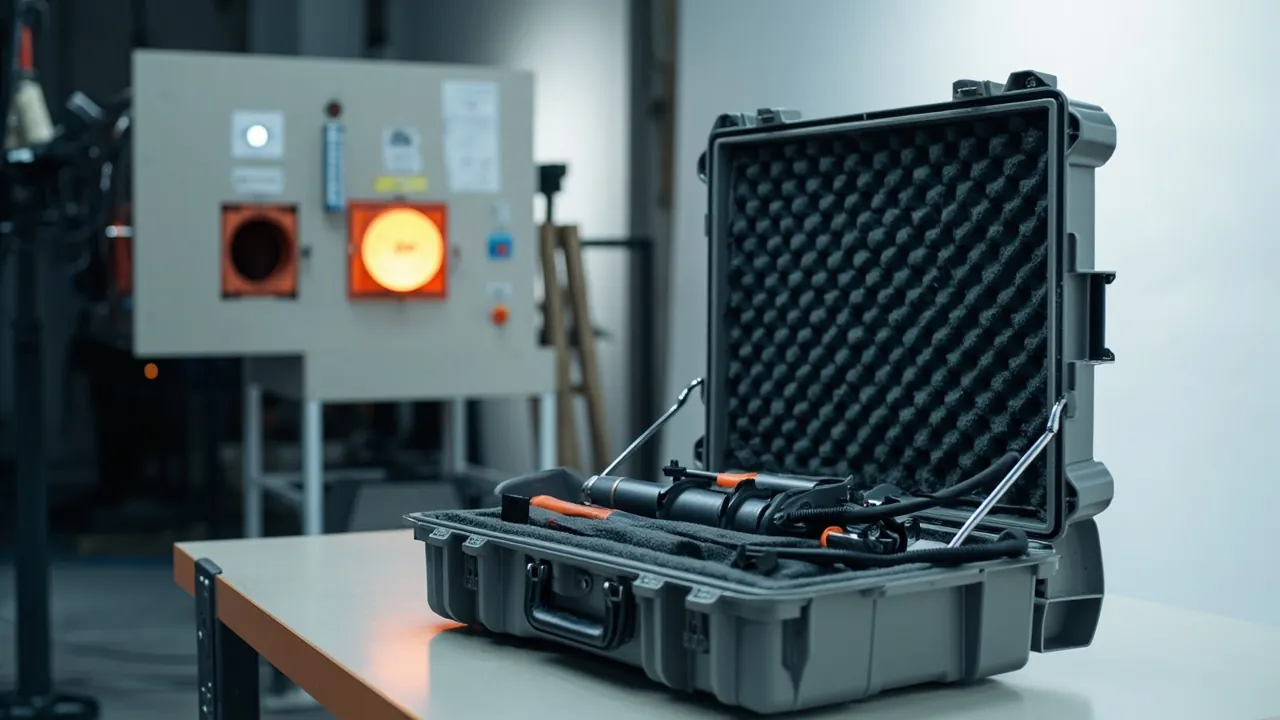
The central problem in a heat-treatment equipment case is not impact resistance. It is the combined effect of thermal history, brittle materials and metrological precision. The headline conclusion is that most furnace components arrive for shipping after long service at temperature: metal parts already carry oxidation and thermal fatigue, ceramic-fiber parts carry moisture and dust, and thermocouples and controllers are precision measuring instruments. The first design objective is therefore zone separation, rigid support and humidity control, not a thicker shell. Sealing to IP65 under IEC 60529 and GB/T 4208 is only the sealing threshold. What actually determines delivery quality is whether thermocouples and compensating cables stay untensioned for the whole journey, whether ceramic-fiber modules avoid compression and moisture, and whether heavy items such as furnace rollers and baskets are supported along their full length.
This article is written for equipment engineers and buyers at heat-treatment shops, forging and casting plants, and furnace manufacturers. It works through shells and doors, insulation modules, heating elements, thermocouples, controllers, rollers and baskets, and quench-tank circulation hardware item by item, and provides liner comparison tables, a standards reference list, and acceptance steps that can be written straight into a procurement technical agreement. If you also manage global spare-parts allocation, see the instrument case selection guide for a consistent specification baseline.
Table of Contents
- 1. Transport Risk Profile: Thermal History, Brittleness and Metrology Stacked Together
- 2. Shell and Door Components: Door Frames, Sealing Faces and Door Distortion
- 3. Ceramic Fiber and Insulation Modules: Moisture, Compression and Dusting
- 4. Heating Elements and Radiant Tubes: Scale, Brittle Fracture and Long-Part Support
- 5. Thermocouples and Compensating Cables: The First Line of Temperature Accuracy
- 6. Controllers and Power Regulators: Vibration and Moisture for Precision Electronics
- 7. Furnace Rollers, Belts and Baskets: Support and Rigging for Heavy Parts
- 8. Quench Tanks and Circulation Systems: Residual Media and Liquid Separation
- 9. Liner Options Compared: EVA, PE, PU, EPP and Wooden Skid Combinations
- 10. Sealing, Pressure Equalization and IP Ratings: How to Use the Standards Correctly
- 11. Environmental and Transport Testing: The Boundaries of MIL-STD-810H and ISTA
- 12. Material Compliance and Package Marking: UL94, Timber and Handling Symbols
- 13. Acceptance, AQL Sampling and OEM/ODM Collaboration
- Frequently Asked Questions
- Conclusion & Related Reading
1. Transport Risk Profile: Thermal History, Brittleness and Metrology Stacked Together
Heat-treatment equipment has a characteristic that is easy to overlook: most of it has already served at high temperature under oxidation and thermal cycling, so it is not in new-equipment condition when it is packed. A cart-bottom furnace that has run for a year may already have a slightly warped hearth plate, radiant tubes carrying surface scale, and ceramic-fiber lining that has been through dozens of thermal cycles. These latent conditions are hard to see before packing, and the vibration, moisture and stacking pressure of transport turns them into visible defects.
Four risk categories need separate treatment.
First, brittle fracture. Ceramic fiber modules, silicon carbide elements, molybdenum disilicide elements, graphite parts, ceramic insulators and alumina tubes are all low-toughness materials. Their impact resistance at room temperature is far below their behavior at temperature, and a single 20 cm to 30 cm drop can create a through-crack that only shows up as breakage or a hot spot after the furnace is fired.
Second, loss of metrological accuracy. Thermocouples, compensating cables, controllers and recorders form a measurement chain. Under the pyrometry logic expressed in AMS 2750 and CQI-9, damage to any link affects the conclusions of temperature uniformity surveys (TUS) and system accuracy tests (SAT). This means a thermocouple is not a piece of metal stock, and a compensating cable is not ordinary cable to be coiled tight.
Third, heavy-load impact and permanent deformation. Furnace rollers, baskets, trays, radiant tubes and door frames are heavy items, often in the 30 kg to 800 kg range. Sustained vibration crushes support faces locally, and long parts such as rollers and radiant tubes sag permanently when they are fixed only at the two ends.
Fourth, moisture absorption and corrosion. Ceramic fiber that has absorbed water shows higher thermal conductivity and lower compressive strength. Carbon steel and tool steel develop condensation corrosion above roughly 60 percent relative humidity with temperature cycling. Electrical components lose insulation resistance when damp, and can track on power-up.
Put these four together and it becomes clear why a heat-treatment case must be designed from zoning and support outward, not from shell thickness inward. For seal material selection in this alternating temperature environment, see protective case seal materials.
The table below gives reference protection parameters for common heat-treatment parts and equipment.
| Part or equipment | Typical weight | Primary risk | Recommended liner | Buffer thickness | Notes |
|---|---|---|---|---|---|
| --- | --- | --- | --- | --- | --- |
| Door and frame | 40-300 kg | Sealing face impact, door distortion | Timber frame plus PE blocks | 25-40 mm | Ship vertically, cover sealing face |
| Ceramic fiber module | 5-40 kg each | Moisture, compression set, dusting | Individual moisture bag plus shallow tray | No extra buffer needed | Keep compression under 10 percent |
| Heating wire and strip | 2-25 kg | Distortion, scale shedding | PE shallow channel plus non-woven separator | 15-25 mm | Never stack multiple pieces |
| Radiant tube and furnace roller | 30-500 kg | Permanent bending, flange damage | Multi-point rigid cradle | 20-30 mm | Support points along full length |
| Silicon carbide or MoSi2 element | 1-10 kg | Room-temperature brittle fracture | PU foam cell plus rigid sleeve | 10-15 mm | No unsupported span allowed |
| Sheathed thermocouple | under 2 kg | Excess bending, terminal head damage | PE cut individual channel | 10-15 mm | Minimum bend radius 5x outer diameter as a working rule |
| Noble-metal thermocouple (S, R, B) | under 1 kg | Brittle wire breakage, contamination | Rigid tube case plus separate cell | 10-15 mm | Pack alone, no rubbing against metal |
| Controller and recorder | 1-8 kg | ESD, condensation, solder fatigue | Anti-static EVA individual cell | 20-30 mm | Add desiccant |
| Thyristor power regulator | 3-25 kg | Heat-sink distortion, busbar loosening | EVA 40D plus rigid support | 25-35 mm | Clean heat-sink fins first |
| Basket and tray | 20-300 kg | Stack crush, corner deformation | Wooden skid plus local rubber pads | 15-25 mm | Limit stack height |
| Quench agitator and heat exchanger | 20-150 kg | Residual media seepage, flange distortion | PE liner plus absorbent pad | 30-40 mm | Must be drained and capped |
2. Shell and Door Components: Door Frames, Sealing Faces and Door Distortion
Furnace shells and doors are the two large items most likely to be stacked casually, and they generate the largest share of distortion claims.
The shell is usually a welded steel plate structure with reinforcing ribs and lining anchors inside. The risk is not the shell body itself but the mounting flanges, thermocouple entry ports, sight-port flanges and rail mounting faces. Once these machined faces are struck or squeezed, on-site assembly produces gaps, leakage or a furnace body that will not seat. Apply peelable protective film to machined faces and add timber edge boards outside.
The door and door frame carry their critical tolerance at the sealing face. Heat-treatment furnaces normally seal with a sand knife, a labyrinth gasket or graphite packing, and the flatness of that face directly determines leakage rate and energy consumption. Impact during transport creates pits or burrs on the sealing face, and the symptom after assembly is a door that will not close tightly and a furnace with uneven temperature. Recommended measures: fit a rigid protective cover over the sealing face; fix the door vertically and never stack it flat; pack the door and frame separately, each independently restrained.
Door lifting and clamping mechanisms (chains, cylinders, wedges, eccentric cams) are moving parts that get overlooked. If a cylinder rod takes a side load in transit, the rod bends or the bore scores. Coat chains and sprockets with rust-preventive grease and wrap them in inhibitor paper.
Hinges, latches and clamping hardware are the shared weak point of the case and the equipment. If the equipment-side hinge carries the full weight in transit, the pin can deform. For load ratings and selection of case-side hinges and latches, see toolbox hinge, latch and seal selection.
Shells and doors are large, thin sheet-metal weldments with far less rigidity than their appearance suggests. Stacking is their biggest enemy: when a door frame sits in the middle layer of a three-high stack, its distortion commonly exceeds the tolerance allowed for the sealing face. These parts should therefore ship alone or in a dedicated vertical frame, never in the same case as rollers or baskets.
3. Ceramic Fiber and Insulation Modules: Moisture, Compression and Dusting
Ceramic fiber modules, commonly rated at 1260 C or 1400 C classification temperature, are the mainstream lining material in modern heat-treatment furnaces and the most underestimated item in shipping protection.
First, moisture is the primary problem. Ceramic fiber is a porous structure with a very high specific surface area. After bare shipping or long storage in a humid environment, fiber moisture content rises, with two consequences: thermal conductivity increases so the on-site heating curve deviates from design, and the bond strength between fibers drops so the lining sags or spalls after installation. The remedy is a separate moisture-barrier bag for each module, desiccant inside the bag, and confirmation that modules are dry before packing. As a working target, keep relative humidity inside the module package below 60 percent.
Second, compression set is irreversible. Ceramic fiber modules have limited compression recovery. When stacking pressure holds compression above roughly 10 percent for several weeks, the fiber structure collapses permanently, the installed lining thickness becomes uneven, and the local hot-face temperature rises. Modules must sit upright in divided shallow trays. They are not gap filler, and they must never carry the weight of other heavy items.
Third, dusting and abrasion. Fiber modules rubbing against each other generate dust, which contaminates thermocouples, instruments and machined faces in the same case. Use non-woven or PE separators between modules and prevent relative motion inside the case.
Fourth, firebrick and castable preforms. These are stiffer but their corners are fragile. Lightweight insulating brick such as mullite or high-alumina brick loses a corner on the slightest impact, which ruins the mortar joint during bricklaying. Use a PE cut liner with individual cells, cell depth at least 60 percent of brick thickness and 1 mm to 2 mm clearance around each brick.
Fifth, the water resistance of the packaging itself. If a module case uses a cardboard liner, an outer moisture film is needed for long sea transit. If it uses a plastic protective case, a design following the IP67 protective case sealing requirements effectively blocks both liquid water and humid air exchange. Whichever format is used, place a humidity indicator card inside so that the moisture question can be answered on opening rather than argued about later.
4. Heating Elements and Radiant Tubes: Scale, Brittle Fracture and Long-Part Support
Heating elements are high-turnover spare parts in a heat-treatment furnace and a classic case of something that looks like metal but behaves like a brittle material.
Heating wire and heating strip, commonly Cr20Ni80 or Cr27Al7Mo2, develop an alumina or chromia layer in service. That scale sheds under transport vibration and lands on other parts as conductive contamination or hard abrasive grit. Blow the elements clean before packing, wrap them in non-woven fabric, and separate multiple pieces with an interlayer. Never stack them directly: stacking presses coils into each other, and the on-site straightening produces uneven pitch.
Radiant tubes are usually centrifugally cast heat-resistant steel tubes, 1.5 m to 3.5 m long. Two risks dominate: permanent bending and damage to the flange face and welds. The control measure is support along the full length, with support spacing held to roughly 15 to 20 times the tube outer diameter as a working ratio, plus axial restraint at both ends. Cover the flange sealing face and never lift the tube with a wire rope sling around the body.
Silicon carbide and molybdenum disilicide elements show the most pronounced room-temperature brittleness. SiC elements have low flexural strength at ambient temperature, and MoSi2 elements are brittle below about 400 C. They may only travel in a dedicated rigid sleeve, with soft material between sleeve wall and element, and with no unsupported span anywhere. Pack each element individually and mark the package fragile with no stacking allowed.
Graphite parts such as electrodes, loading frames and heating elements are protected mainly against edge chipping and surface contamination. Graphite dislikes water, oil and rub contact with metal parts, which introduces metallic contamination. Use PE cut cells with lint-free paper wrapping and never place graphite in the same cell as steel.
The general rule for long parts deserves its own emphasis: permanent deformation of a long part almost always comes from fixing only the two ends and leaving the middle span free. Distribute support points so the maximum deflection of every span stays inside tolerance, rather than relying on thicker packaging to absorb the load. For structural approaches to replaceable dividers and long-part cradles, see removable divider system design.
5. Thermocouples and Compensating Cables: The First Line of Temperature Accuracy
Thermocouples and their compensating cables are the components inside a heat-treatment case that most deserve to be treated as instruments rather than metal stock.
The calibration type must match on both sides. Common types include K, N, J, T, S, R and B, with the reference tables defined by the IEC 60584 series and the GB/T 16839 series. A compensating cable extends the cold junction to the instrument, and its alloy composition must match the thermocouple type: type K with type K cable, type S with type S cable. Mixing or reversing the pair introduces a systematic error of tens of degrees. When packing a batch, mark the type designator and length on the outside of each bag so that the field team cannot mix them up.
Noble-metal thermocouples of types S, R and B are both expensive and fragile. Wire diameter is often in the 0.3 mm to 0.5 mm range, and bending, tension or rubbing against a hard object can damage the grain structure internally. The unit then looks perfect but drifts in measurement. Give each one a rigid tube case, keep the wires clear of every other item, and cushion the terminal head.
Bending limits for sheathed thermocouples. A sheathed thermocouple can be bent, but too tight a radius creates voids between the magnesium oxide insulation and the sheath. As a working rule keep the minimum bend radius above five times the outer diameter, and avoid repeated bending at the same location.
Storing compensating and extension cables. These cables should not be coiled to a small radius like ordinary power cable, and they should not be crushed under heavy parts. Wind them onto a spool at least 200 mm in diameter, cap both ends, secure the coil with a soft tie and never tie a hard knot.
Handling and re-verification on arrival. Under the pyrometry management logic of AMS 2750 and CQI-9, a thermocouple has a grade and a tolerance and an instrument has an accuracy type; the chain needs a documented confirmation step. The point is not that transport will necessarily cause a drift, but that the integrity of the measurement chain deserves a traceable confirmation action. A procurement agreement can require a copy of the factory calibration certificate in the case and re-verification on arrival under the buyer's own procedure. For the general logic of equipment-level verification, see MIL-STD-810H environmental test basis. That standard is a set of environmental test methods and does not constitute military certification.
6. Controllers and Power Regulators: Vibration and Moisture for Precision Electronics
Temperature controllers, recorders, thyristor power regulators, solid-state relays, PLCs and oxygen probes are electronic items whose protection logic is entirely different from mechanical parts.
First, vibration damage appears as solder fatigue. Capacitors, relays and terminal blocks inside these units are soldered to the board by their leads. Sustained vibration creates fatigue cracks at solder joints, a failure that often appears months after delivery and is very hard to localize. Use at least 20 mm to 30 mm of buffer thickness and eliminate hard points that connect directly to the unit.
Second, condensation damage appears as falling insulation resistance. A temperature controller contains a high-impedance input circuit, and moisture lowers that impedance so the reading jumps. A workable ratio is 100 g of silica gel desiccant per 50 L of internal case volume, adjusted for transit duration and climate zone. Choose a case and seal structure with low moisture vapor transmission; see waterproof case and IP rating implementation.
Third, static damage is invisible. Human-body static during removal and packing can puncture a CMOS input stage. Wear a wrist strap during handling and use anti-static bags or anti-static liner material. See ESD shield case design.
Fourth, oxygen probes and carbon-potential sensors are a special case. An oxygen probe contains a zirconia ceramic tube that is extremely brittle at room temperature, and the reference-air passage at the tip is sensitive to blockage and oil. Pack the whole unit in a rigid protective tube, fit a dust cap on the tip and never store it inverted.
Fifth, settling time on arrival. Let the unit equilibrate at ambient temperature for 4 to 8 hours before power-up so it reaches thermal balance with the room and avoids a condensation-driven short circuit.
7. Furnace Rollers, Belts and Baskets: Support and Rigging for Heavy Parts
These are the heaviest items in a heat-treatment spare-parts case and the ones that most test the structural design of the box.
Furnace rollers are usually centrifugally cast or forged heat-resistant steel, 60 mm to 300 mm in diameter, 1.5 m to 4 m long, and 50 kg to 800 kg each. Their key characteristics are straightness and journal roundness, with straightness typically called out in the 1 mm/m to 2 mm/m range as a working value, subject to the equipment drawing. The support method decides the outcome: use at least three support points, with the end points near the journals and the middle point at mid-span, and use timber or polyurethane cradles so contact is by area rather than by line. Protect journals and bearing seats with sleeves against impact and corrosion.
Wire belts and chain plates are flexible long items at risk of cuts, kinks and local stretching. Coil or fold them and tie with soft straps positioned away from the belt edges, and place the coil in a shallow tray rather than directly on a hard case floor.
Baskets and trays in cast or welded heat-resistant steel are heavy, hard and sharp-cornered. They dent the case when they collide in transit. Use a wooden skid plus rubber pads: the skid carries the load and spreads it to the forklift pockets, while the rubber provides local elasticity to absorb impact. Limit stacking to two or three layers with timber separators between layers.
Rigging and restraint must match the case structure. Anchor points belong on reinforced areas such as skid bottom rails or steel corner fittings, never directly on the case wall. For handling design on heavy wheeled cases, see case wheels and trolley handle design.
The table below matches heavy items to case structure recommendations.
| Heavy item | Unit weight range | Recommended case type | Base format | Support points | Restraint method |
|---|---|---|---|---|---|
| --- | --- | --- | --- | --- | --- |
| Roller, length under 2 m | 50-250 kg | Tall vertical case | Wooden skid, twin rails | 3 | Journal clamps at both ends |
| Roller, length 2-4 m | 150-800 kg | Steel-timber composite frame | Steel base rail plus skid | 4 or more | Dedicated cradle plus straps |
| Radiant tube | 30-300 kg | Long case or dedicated rack | Wooden skid | 3-4 | Flange end stop plus mid straps |
| Basket and tray | 20-300 kg | Pallet-style case | Skid plus rubber pads | Area contact | Layer separators plus top clamp |
| Wire belt and chain | 40-400 kg | Drum or shallow tray | Wooden skid | Area contact | Soft strap ties |
| Quench agitator | 20-150 kg | Vertical case | Skid plus PE blocks | Area contact | Flange bolts |
8. Quench Tanks and Circulation Systems: Residual Media and Liquid Separation
Quench tanks, agitators, heat exchangers and lift mechanisms are common spares on carburizing and hardening lines, and their protection brief centers on the boundary of residual media.
Residual quench oil and polymer quenchant must be dealt with before packing. An agitator, heat exchanger or pipe run pulled from service normally carries oil or polymer residue that will seep during transit, contaminate the liner and other parts, and sharply reduce the friction that holds the load in place. The recommended sequence is: drain the tank, remove and pack the impeller separately, blow the lines through with compressed air, cap all ports, and confirm no dripping before packing.
Build a liquid bay into the structure. Divide the case into a wet zone with replaceable absorbent pads and a dry zone separated by a solid partition. Even if a part still seeps slightly, contamination stays local. For design ideas on liquid separation and replaceable liners, see custom foam insert solutions.
Be explicit about the compliance boundary. Quench oil is an oil-based chemical whose transport and storage fall under dangerous goods rules. A protective case provides mechanical protection and contamination isolation; it does not replace the classification, packaging, marking and documentation required for dangerous goods. For cross-border movements, follow the classification, packing and marking rules covered in ADR/IMDG hazmat transport case requirements, and state in the agreement that the case is not a chemical storage container.
Heat exchangers rarely drain completely. Plate-pack channels and tube bundles both trap media. Dismantle or blow through repeatedly. Gaskets in nitrile, fluoroelastomer or PTFE deform under load and age over time, so store them flat, separately, away from stacking and direct sun.
9. Liner Options Compared: EVA, PE, PU, EPP and Wooden Skid Combinations
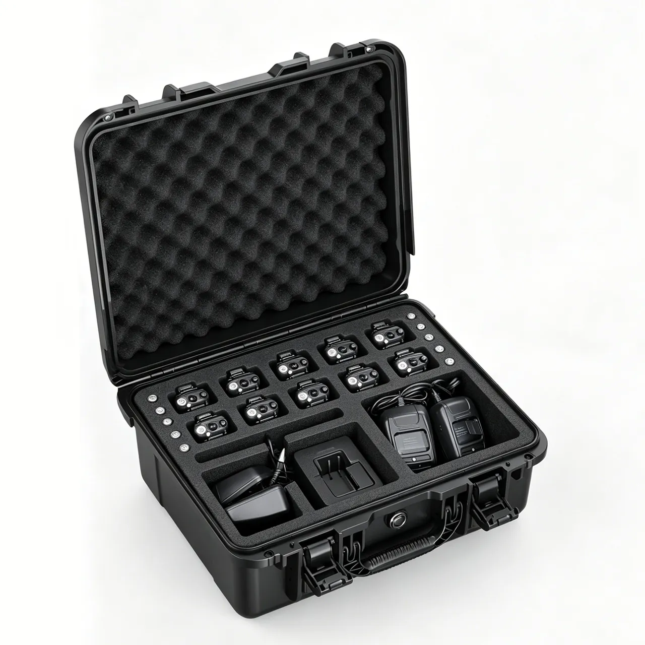
The liner in a heat-treatment equipment case is rarely a single material. It is a combination of a structural element, an elastic element and a separator. The table below compares the common materials as a basis for the material clause in a procurement agreement.
| Material | Typical density or hardness | Cushioning | Temperature orientation | Main applications | Cost orientation |
|---|---|---|---|---|---|
| --- | --- | --- | --- | --- | --- |
| EVA (ethylene-vinyl acetate) | 30D-70D | Moderate, good recovery | Ambient to moderate; keep below 60-70 C for long-term use | Instruments, regulators, small castings | Medium |
| PE cut foam (polyethylene) | 25-45 kg/m3 | Low, primarily locating | Ambient, good low-temperature behavior | Cells, long thin parts, thermocouples | Medium to high (CNC dependent) |
| PU foam (polyurethane) | 20-35 kg/m3 | High, good energy absorption | Ambient | SiC elements, optical and precision parts | Medium |
| EPP (expanded polypropylene) | 30-60 g/L | High, multi-impact recovery | Ambient, better temperature tolerance than EPS | Base of heavy parts, forklift pallets | Medium to high |
| Timber skid and plywood | Structural | No cushioning | Ambient | Load base, impact spreading | Low |
| Rubber pad (NBR or EPDM) | 60-80 Shore A | Local elasticity | Ambient to roughly 100 C | Contact faces with metal heavy parts | Low |
| Foil-laminate moisture film | Film | No cushioning | Ambient | Moisture barrier, outer wrap for fiber | Low |
Three combination principles summarize the practice. First, structure carries the weight, elasticity absorbs the impact, and the cut liner does the locating. Do not ask foam to carry load and locate at the same time. Second, use rubber or polyurethane wherever a heavy metal part touches down, so that metal cannot crush foam directly. Third, every surface touching electronics or fiber must be clean, dust-free and oil-free. For a quantitative comparison of cushioning behavior, see case foam material comparison.
10. Sealing, Pressure Equalization and IP Ratings: How to Use the Standards Correctly
The IP rating is the most misused line in procurement documents. IEC 60529 and GB/T 4208 define a enclosure's protection against solid foreign objects and water. They promise nothing about impact resistance, stacking strength or corrosion performance.
- IP65: dust-tight and protected against water jets. Suitable for road transport and covered storage, and the normal starting point for industrial equipment cases.
- IP67: dust-tight and protected against temporary immersion, typically tested at 1 m for 30 minutes. Suitable for sea freight, open transfer yards and washdown environments.
- IP68: protected against continuous immersion, with conditions agreed between manufacturer and user. The depth and duration must be written into the procurement document.
Pressure equalization is a necessary companion to a sealed case. A sealed case experiences temperature swings during transport, from sun exposure by day to cooling at night, and altitude changes on sea and air legs. The resulting pressure differential repeatedly compresses the gasket, which over time can cause permanent set or seal failure. Fitting a watertight breather valve preserves the IP rating while removing the differential. For valve selection and placement, see protective case pressure equalization valve design.
Temperature matching for seals. Ambient temperature in a heat-treatment shop runs high, and if the case is stored near a furnace, the service temperature of the gasket must be confirmed separately. Among common seal materials, nitrile rubber covers ambient to roughly 100 C, and silicone rubber reaches higher temperatures but wears faster. Write the maximum long-term storage temperature into the procurement agreement, not just the IP rating.
11. Environmental and Transport Testing: The Boundaries of MIL-STD-810H and ISTA
Transport protection should not rest on a feeling that the packaging is good enough. It needs a citable test framework. Four groups of standards are commonly combined.
First, the ISTA series. ISTA Series 1 covers basic performance tests, Series 2 covers partial simulation, Series 3 covers general simulation, and Series 6 addresses thermally controlled transport packaging. For heat-treatment spare-parts cases, 2A for individual packages up to 68 kg and 3E for unitized loads over 68 kg moving as LTL freight are the most frequently cited. For test sequences and selection logic, see the ISTA transport testing procedure.
Second, the GB/T 4857 series. This series specifies basic test methods for transport packages, including drop, stacking, vibration, impact and water spray. For domestic contracts, citing this series is often easier for third-party laboratories to execute than citing a foreign standard. See GB/T 4857 transport packaging in practice.
Third, ASTM D4169. This standard is organized around a distribution cycle and combines test sequences through a DC number; DC 13 is commonly used for a single-package air and ground combination. Its advantage is that test severity can be tailored to the actual logistics chain. See ASTM D4169 distribution cycle testing.
Fourth, MIL-STD-810H. This standard provides environmental test methods for vibration, shock, temperature and humidity, and low pressure. It should be stated clearly that citing this standard means only that its test methods are used as the basis for environmental verification. It does not constitute military certification or a military qualification. Procurement documents should say "with reference to the relevant MIL-STD-810H test methods" to avoid ambiguity.
For heat-treatment spare-parts cases, a sensible test combination is vibration for long road and rail legs, drop or shock for handling, stacking for warehouse and container loading, and temperature-humidity cycling for sea freight and cross-climate routes. Thermocouples and instruments deserve a separate loaded vibration test, because their failure mode is cumulative and a whole-case test will not localize it.
12. Material Compliance and Package Marking: UL94, Timber and Handling Symbols
First, flame retardancy of foam and plastic parts. Liners, dividers and molded case parts should meet the relevant UL94 classification such as HB or V-0. In a heat-treatment shop where high-temperature sources are present, the flame retardancy class of liner material belongs in the technical agreement, especially where electrical parts share a case.
Second, phytosanitary requirements for timber packaging. Export pallets and wooden crates must comply with ISPM 15, be heat treated (HT) or fumigated (MB), and carry the IPPC mark. Plywood, which is pressed at high temperature, is normally exempt, but confirm the destination country requirements with the carrier anyway.
Third, handling symbols. Mark packages under GB/T 191 with fragile, this way up, keep dry, do not roll and stacking limit symbols. For thermocouples and SiC elements, both the fragile symbol and the do-not-roll symbol are mandatory.
Fourth, reference for rust prevention. For carbon steel and tool steel parts, the approach in GB/T 4879 rust-preventive packaging can be used to select the material grade, combining VCI film, rust-preventive oil and desiccant, with the protection period stated in the contract, for example 12 months.
Fifth, the dangerous goods boundary. If a case contains chemicals such as quench oil or cleaning agents, their outer marking and documentation follow the applicable dangerous goods rules. The protective case itself is not used as dangerous goods packaging.
13. Acceptance, AQL Sampling and OEM/ODM Collaboration
To turn the requirements above into executable procurement actions, work through the following checklist.
Design confirmation stage:
- Confirm the parts list, unit weights, maximum envelope dimensions and center of gravity.
- Confirm the number and positions of support points; long parts need a support spacing calculation or a documented working basis.
- Confirm how the liner contacts each part surface, with area contact preferred.
- Confirm the wet and dry zoning and the replaceability of absorbent pads.
- Confirm whether a pressure equalization valve is fitted, and its position and orientation.
Sample verification stage:
- Check the assembly tolerances and the feel of seals, hinges and latches.
- Verify sealing performance at the specified IP rating, using a third-party report where available.
- Run the agreed loaded vibration, drop and stacking sequence.
- Verify that thermocouple and instrument type designators match the packing list.
Volume delivery stage:
- Build the AQL plan following the sampling logic of GB/T 2828.1, classifying appearance, structural and marking defects separately. See custom case acceptance and AQL sampling.
- Randomly open cases each batch to check liner fit and fastener torque.
- Verify handling symbols, IPPC marks and accompanying documents.
OEM/ODM collaboration models. For furnace builders and spare-parts distributors, the usual requirement is a liner cut for a specific equipment model, markings under the customer's own brand, and staged delivery against an annual framework. JUNZHJIA (Kexin New Materials (Guangdong) Co., Ltd.) provides CNC-cut liners to part drawings, matched seals and latches by model, and inspection documents covering IP rating and whole-case testing, and it accepts OEM/ODM and wholesale agency business. For the full factory assessment and sampling workflow, see how to choose a protective case OEM factory.
Frequently Asked Questions
Q: Does a heat-treatment equipment case have to reach IP67, or is IP65 enough?
A: It depends on the logistics route and environment, not on a preference for higher numbers. IP65 means dust-tight and protected against water jets, which suits road transport, covered storage and in-plant transfer, and it is the sensible starting point for most heat-treatment spare-parts cases. IP67 adds temporary immersion, typically tested at 1 m for 30 minutes, and suits sea freight with transshipment, open storage yards, rainy-season loading and cases that need washdown cleaning. Three questions settle the choice: is there any risk of open storage or short-term standing water; does the route include sea freight with its humidity and condensation cycles; and will the case be washed after arrival? One caution matters more than the rating itself. An IP rating describes only protection against solids and water, and says nothing about impact resistance, stacking strength or corrosion performance. Even at IP67, buffer thickness, support structure and liner material still have to be specified separately. If the case will also be stored in a hot area, state the maximum long-term storage temperature in the agreement, because the service temperature of the gasket limits the validity of the IP rating. For moisture-sensitive ceramic fiber modules, add a separate barrier bag and a humidity indicator card on top of the IP rating.
Q: What is the biggest transport risk for thermocouples and compensating cables, and how should they be packed?
A: The biggest risk is not visible impact damage but invisible drift in measurement performance. Noble-metal thermocouples of types S, R and B commonly use wire 0.3 mm to 0.5 mm in diameter, and bending, tension or rubbing against a hard object can damage the internal grain structure, leaving a unit that looks perfect but reads with a systematic offset. A sheathed thermocouple can be bent, but too tight a radius creates voids between the magnesium oxide insulation and the sheath. A compensating cable coiled to a small radius or crushed under a heavy part suffers local stretching of its alloy conductors. Pack in four steps. First, give each thermocouple its own rigid tube case with the wires touching nothing else. Second, keep the minimum bend radius of a sheathed thermocouple above five times the outer diameter and avoid repeated bending at one point. Third, wind compensating cables onto a spool at least 200 mm in diameter, cap both ends and never tie a hard knot. Fourth, mark the type designator and length, for example type K, 3 m, on the outside of each bag so the field team cannot mix them. Under the IEC 60584 and GB/T 16839 reference tables, type K must pair with type K cable; a mismatch introduces a significant systematic error. Require a calibration certificate copy in the case and re-verification on arrival.
Q: Can ceramic fiber lining modules travel by sea inside a sealed case, and what needs attention?
A: Yes, but only after the moisture and compression problems have been solved, because a sealed case can otherwise hide a developing problem rather than prevent it. Ceramic fiber is porous with a very high specific surface area, and after bare shipping or long storage in humid conditions its moisture content rises. Thermal conductivity then increases so the on-site heating curve departs from design, while the bond strength between fibers falls so the lining sags and spalls after installation. The correct approach is a separate moisture-barrier bag for each module, desiccant inside the bag, confirmation that modules are dry before packing, and relative humidity inside the package held below 60 percent. On compression, recovery is limited: when stacking holds compression above roughly 10 percent for several weeks, permanent collapse occurs. Modules must stand upright in divided shallow trays, must not be used as gap filler, and must never carry the weight of other heavy items. Between modules, add non-woven or PE separators so that rubbing does not generate dust that contaminates thermocouples, instruments and machined faces in the same case. Finally, place a humidity indicator card in every module case and mark the outer box keep dry and this way up. Reading the indicator card first on arrival turns the moisture question into a verifiable fact rather than a dispute.
Q: How should long heavy parts such as furnace rollers and radiant tubes be supported so they do not bend?
A: The core principle is to support along the full length so that no span is left unsupported. Furnace rollers are usually centrifugally cast heat-resistant steel, 60 mm to 300 mm in diameter, 1.5 m to 4 m long and 50 kg to 800 kg each, with straightness typically called out in the 1 mm/m to 2 mm/m range, subject to the equipment drawing. Permanent bending almost always comes from fixing only the two ends: the middle span oscillates with the road, stress concentrates near the supports, and a plastic bend forms. Use at least three support points, with the end points near the journals and the middle point at mid-span, and increase to four or more for parts longer than 2 m. A working upper limit for support spacing is 15 to 20 times the tube outer diameter. Choose timber or polyurethane cradles so contact is by area rather than by line, which prevents local indentation. Protect journals and bearing seats with sleeves that guard against both impact and corrosion. Radiant tubes also need flange sealing faces covered, and must never be lifted with a wire rope sling wrapped around the body. Anchor straps to reinforced areas such as skid bottom rails or steel corner fittings rather than to the case wall, so that restraint force does not distort the panel. For rollers above 300 kg, use a steel-timber composite frame instead of an all-timber base and run a loaded lifting trial before dispatch.
Q: Do thermocouples and temperature controllers need re-verification after transport, and under which standard?
A: Re-verification is advisable, and the action should be written into the acceptance procedure rather than left to on-site judgment. The basis is the pyrometry management logic expressed in AMS 2750 and CQI-9: thermocouples have grades and tolerances, instruments have accuracy types, and the whole measurement chain is confirmed through system accuracy tests and temperature uniformity surveys. Those standards govern temperature measurement in production heat treatment, and transport falls outside their scope, so the practical engineering approach is to use the same management logic to constrain transport protection in reverse. Three steps follow. First, require a factory calibration certificate copy in the case, stating type designator, grade, calibration date and calibration points. Second, any thermocouple or instrument that has been through long-distance transport, a suspected drop or damaged packaging should receive a comparison check or recalibration before being placed in service. Third, inspect sheathed thermocouples for abnormal bending and loose terminal heads, and inspect noble-metal thermocouples specifically for kink marks on the wires. The point is not that transport necessarily causes drift; it is that the integrity of a measurement chain deserves a traceable confirmation step. Writing that step into the procedure turns a possible dispute about uneven temperature after delivery into a documented process node, which benefits both buyer and supplier.
Q: What drives the cost of a custom liner, and is small-batch production realistic?
A: Four cost elements dominate. The first is tooling and programming: a CNC-cut liner needs toolpath design from a 3D part model, and the more complex the part shape and the more cells required, the longer the programming and setup time; volume exists to spread this fixed cost. The second is material: EVA, PE, PU and EPP differ notably in unit price and density, and switching a single case from 45D EVA to 30 kg/m3 PE can change material cost by tens of percent, while heavy parts also need skids, rubber pads and steel base rails. The third is machining time: cut depth, profiled channels, stepped cavities and multi-layer structures differ widely in cycle time. The fourth is verification: if the buyer requires loaded vibration, drop and stacking tests on the whole case, or a third-party IP rating report, that cost must be counted separately. Small batches are entirely workable. The usual route is a single sample to confirm fit tolerances and the feel of insertion and removal, followed by staged production against an annual framework. For customers running many models on one line, a combination of a common support base plus model-specific shallow trays concentrates the customization cost in a replaceable tray layer and lowers changeover expense. JUNZHJIA provides liner samples and fit verification from part drawings, with matched seals and latches by model.
Q: Do export pallets need fumigation, and what other packaging requirements apply?
A: It depends on the pallet type. Solid timber pallets and timber crates are regulated wood packaging and should comply with ISPM 15, using heat treatment (HT) or methyl bromide fumigation (MB), with the IPPC mark applied in a visible position. Pallets made from plywood, particleboard or other engineered panels are normally exempt, but confirm with the carrier and the destination country anyway, because some markets impose additional rules on engineered wood. Beyond timber, three points apply to export packaging. First, handling symbols under GB/T 191: fragile, this way up, keep dry, do not roll and stacking limit. Cases containing thermocouples, silicon carbide elements or ceramic fiber modules must carry both the fragile and the do-not-roll symbols. Second, rust prevention: for carbon steel and tool steel parts, use the approach in GB/T 4879 to select the material grade, combining VCI film, rust-preventive oil and desiccant, and state the protection period in the contract, for example 12 months. Third, the dangerous goods boundary: if a case contains quench oil or cleaning agents, their outer marking and documentation follow the applicable dangerous goods rules, and the protective case itself is not used as dangerous goods packaging. Put all four items, IPPC mark, handling symbols, rust protection period and dangerous goods responsibility, into the export contract separately.
Q: How should a batch of heat-treatment equipment cases be accepted, and how should AQL sampling be set up?
A: Accept in three stages and set decision rules following the sampling logic of GB/T 2828.1. Stage one is arrival inspection and document check: verify handling symbols, IPPC marks, packing list and type designator labels against each other; inspect for through-cracks, distortion and detached gaskets; open cases to look for dusting, contamination and crushed liner. Stage two is functional checking: spot-check that pressure equalization valves breathe freely; sample hinge and latch operating force and end stops; check fastener torque on skid and base rail joints for heavy cases. Stage three is test verification: run the agreed loaded vibration, drop or shock and stacking sequence, and give thermocouples and instruments their own loaded vibration test because their failure mode is cumulative. For the AQL plan, classify defects into three groups. Critical defects such as seal failure, structural cracking of the case and fracture of a support member should be set at AQL 0. Severe defects such as partial gasket separation, out-of-tolerance liner cell dimensions and latch failure generally fall between AQL 0.65 and 1.5. Minor defects such as cosmetic scratches, print misregistration and slightly unclear marking generally fall between AQL 2.5 and 4.0. Determine sample size from the lot size, normally at general inspection level II. Keep opening photographs and test records from each batch as the basis for later traceability.
Conclusion & Related Reading
The design logic of a heat-treatment equipment case compresses into one sentence: identify what each part fears, then decide what the case must do. Shells and doors fear stacking and impact; ceramic fiber modules fear moisture and compression; heating elements fear unsupported spans and stacking; thermocouples and instruments fear tension and condensation; rollers and baskets fear mid-span sag and local crushing. Match each risk to rigid support, moisture-barrier packaging, individual cells, a defined desiccant ratio and wet-dry zoning, then add citable IP ratings and a transport test framework, and transport damage turns from an uncontrollable variable into a manageable process.
For buyers, the most valuable action is not a thicker shell but three clauses in the technical agreement: the number and location of support points, the contact method at the liner interface, and the verification and sampling rules that apply on arrival. For furnace builders and spare-parts distributors, standardizing liners by model and platforming seals and latches is the most direct way to lower the cost of global spare-parts allocation. JUNZHJIA supports liners cut to drawings, seals matched by model, and inspection documents covering IP rating and whole-case testing, and it accepts OEM/ODM and wholesale agency collaboration. Bring your parts list and logistics route and we can work through the specification together.
Related Reading