


Ladles and furnace-front equipment are where three difficult attributes meet: high temperature, heavy load and precision. Ladle trunnions, tilting mechanisms, pouring spouts and refractory linings, along with burner nozzles, refractory shapes and valve assemblies, all work under radiant heat close to the melting point of the metal, yet many of them are precision-fitted machine parts. The conclusion up front: a foundry ladle and furnace-front case is not an ordinary toolbox. It is a combined protection system covering pre-packing heat treatment, heavy-load support, moisture and impact protection and traceability. Ladle bodies and tilting mechanisms need heavy-duty cradles and profile location to prevent distortion and impact damage. Burners and valve assemblies need separate compartments, moisture control and dust control. The shell should be rated at least IP65, with IP67 recommended for ocean-freight export or open-yard storage. Above all, every component that still carries residual heat or residue must be cooled, cleaned and safety-cleared before it goes anywhere near a case.
The lessons in the field tend to be heavier than expected. Many foundries invest heavily in refractories and safety, yet still pack spares the old way, with a timber pallet, waste cotton and stretch film. A modestly priced trunnion picks up a burr in transit and has to be dressed on site before it will fit. A burner assembly absorbs moisture, its refractory shape cracks, and the burner flashes back on first light-up. Or worse, a ladle component still carrying residue and warmth sits in a closed case for several days, and on opening there is both condensation corrosion and a risk of gas accumulating from the residue.
This article works backwards from failure modes to packaging design, and gives pre-packing heat treatment, heavy-load support, moisture and impact protection, safety boundaries and an inspection checklist for equipment engineering, furnace-front management, spare-part procurement and HSE teams in foundries.
Table of Contents
- 1. Why Foundry Ladles and Furnace-Front Equipment Need Dedicated Cases
- 2. Where Ladle Bodies Fail: Linings, Spouts, Trunnions and Tilting Mechanisms
- 3. Burners and Combustion System Components: Nozzles, Refractory Shapes and Valve Assemblies
- 4. Pre-Packing Treatment of Hot Components: Cooling, Cleaning and the Temperature Release Line
- 5. Moisture and Impact Protection for Refractories: Linings and Precast Shapes
- 6. Case Shell Selection: IP Rating, Material and Load Capacity
- 7. Insert Design: Profile Location, Compartments and Contact Surface Control
- 8. Moisture Control and Job Safety: Desiccants, Combustible Gas Awareness and Boundaries
- 9. Vibration and Shock: ISTA, ASTM D4169 and GB/T 4857
- 10. Heavy Lifting and Transport Securing: Trunnions, Rigging and Centre of Gravity
- 11. Incoming Inspection, Traceability and AQL Sampling
- 12. Custom Workflow and OEM/ODM Delivery
- 13. Selection Decision Tables and Common Misconceptions
- Frequently Asked Questions
- Conclusion & Related Reading
1. Why Foundry Ladles and Furnace-Front Equipment Need Dedicated Cases
Foundry production is a classic example of furnace and machine running as one system. Melting furnace, holding furnace, pouring machine, ladle and casting line interlock closely, so a quality shortfall in any one stage propagates straight into takt time and casting quality. Ladle and furnace-front spares have three traits in common: the change window is short, the cost of stopping is high, and the spare itself often needs on-site fitting before it will go in.
From a protection engineering standpoint, three characteristics rule out generic packaging.
- Structurally heavy and precise at the same time. Ladle trunnions, tilting mechanisms and spout adjustment mechanisms carry heavy loads, but their mating surfaces, including bearing seats, gear flanks, cylinder pivot points and seal seats, are held to meaningful tolerances. Transport damage to heavy parts is usually not fracture but crushing, scoring and micro-distortion of those mating surfaces.
- Materials that are hard and brittle. Refractory materials such as castables, precast shapes and lining bricks are hard, brittle and low in tensile strength, and they fear concentrated load and impact above all. Metal parts are mostly castings or forgings, which develop indentations or microcracks under point loading.
- A hot and dirty service environment. Ladles contact molten metal and slag continuously, so components often carry residue, scale and thermal fatigue cracks on their surfaces. If that residue is not cleaned before packing, it will score mating faces and may generate gases or corrosive substances inside a closed case.
The value of a dedicated case is therefore that it controls mechanical, humidity and contaminant loads during transport and storage at the same time, and eliminates the foundry-specific hazard of hot residue up front. This follows the sensitivity-tiered approach in the instrument case selection guide, with the difference that foundry spares concentrate their sensitivity in heavy-load mating faces and brittle refractory parts.
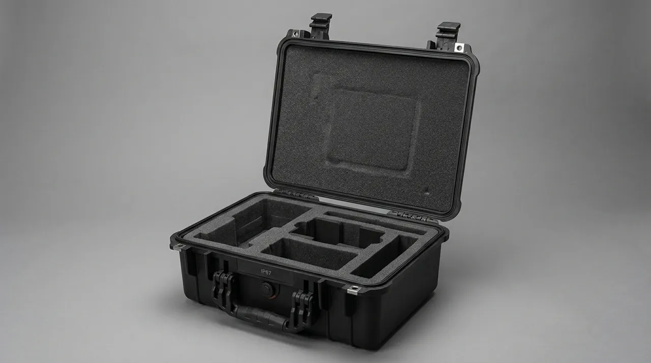
One misconception needs correcting: a sturdy case is not adequate protection. Shell strength solves the problem of the outer box being crushed. Whether a trunnion gets crushed or a refractory shape cracks depends on cradle support position, contact area and cushioning design. The shell is the enclosure. The cradle and insert are the protection.
2. Where Ladle Bodies Fail: Linings, Spouts, Trunnions and Tilting Mechanisms
Ladle structures differ substantially, covering steel ladles, iron ladles, aluminium ladles and tundishes, but the distribution of transport damage follows consistent patterns.
| Location | Structure / material | Typical transport failure | Protection countermeasure |
|---|---|---|---|
| --- | --- | --- | --- |
| Lining / working layer | Castable or refractory brick, brittle | Cracking, spalling, chipped corners | Fully soft support, no point loading, individual wrapping |
| Spout / launder | Thin edge, geometry critical | Chipped edge, distortion, internal damage | Cover or profile block, edge never carries load |
| Trunnion | Critical load-bearing part with precision fits | Crushed journal, scoring, damaged threads | Individual journal sleeve, never a support or lifting point |
| Tilting mechanism (gear ring, worm drive) | Precision gear flanks, sensitive to point load | Gear flank indentation, tooth breakage, bearing seat damage | Gear flank relief plus separate compartment, never with hard parts |
| Cylinder and pivot points | Hydraulic mating surfaces, seal sensitive | Scored piston rod, crushed pivot bore, aged seals | Piston rod sleeve, bore caps, seal storage control |
| Shell and reinforcement rings | Welded structure, good stiffness | Distortion, chipped welds | Non-mating surfaces may carry load, avoid edge loading |
| Seals and gaskets | Rubber or FKM, sensitive to oil, heat and light | Ageing, deformation, tacky surface | Individual sealed bag, away from light and heat, track shelf life |
The critical rule: heavy ladle parts must be supported on non-mating surfaces, with mating surfaces cleared and brittle parts isolated. The most reliable field approach is as follows.
- Shell and reinforcement rings carry the main support. These regions are stiff and non-mating, and are the correct cradle contact zone.
- Trunnions, cylinder pivot points and tilting gear flanks must be fully cleared. They must never be support points and must never touch hard parts.
- Linings and refractory shapes need their own compartments with fully soft wrapping, and must never share a compartment with heavy metal parts.
For the structured design method behind cushioning and support, the cushion liner design guide covers multi-point support and energy dissipation paths, while the case foam material comparison gives the mechanical curves and compression set data needed for a selection review.
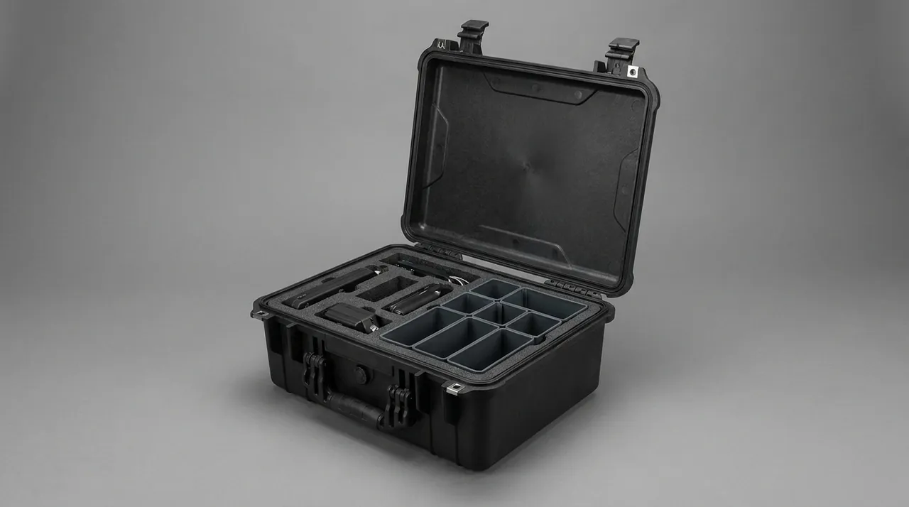
3. Burners and Combustion System Components: Nozzles, Refractory Shapes and Valve Assemblies
Burners and furnace-front combustion components are the most common items mixed into a furnace-front case, and their protection requirements are the ones most often confused.
- Burner bodies and nozzles. The nozzle orifice is small and its geometry is critical, because it sets flame shape and combustion efficiency. Once the orifice deforms or fouls, the flame skews, causing local overheating and potentially flashback. Priorities are a separate compartment, an orifice plug, and a protective sleeve over the outer surface.
- Refractory shapes (burner blocks, castable precast shapes). Brittle, low in tensile strength, and highly vulnerable to concentrated load and impact. They need their own compartments with fully soft wrapping, and must never share a compartment with metal parts.
- Valve assemblies and gas piping components. Fluid control parts with precision mating and sealing faces, and extremely demanding requirements for cleanliness and dryness. Moisture causes stem corrosion and sluggish action. Particulate contamination destroys valve seat sealing. Priorities are individual sealed bags, desiccant and port caps.
- Ignition electrodes, flame detectors and instruments. Brittle, precise, and in some cases static sensitive. They need their own compartments. Where static-sensitive components are present, the zoning and grounding advice in ESD shield case design applies.
- Hoses, metal bellows and expansion joints. Vulnerable to kinking, crushing and sharp-edge scoring. Coil them with a defined minimum bending radius, and never share a compartment with hard heavy parts.
- Refractory fibre products. Sensitive to moisture and compression, and prone to shedding. Refractory fibre that has absorbed moisture generates steam pressure when first heated, which damages the structure, so humidity must be controlled with desiccant and sealing.
For elastomer compatibility and storage limits on valve O-rings and gaskets, seal material and case compatibility collects the practical boundaries between common materials, media and temperatures, and can be used directly in a selection review. The typical foundry problem is exactly this: a valve assembly sits in its case on the furnace platform for months, radiant heat and humidity alternate, the seals age early, and internal leakage appears shortly after commissioning.
4. Pre-Packing Treatment of Hot Components: Cooling, Cleaning and the Temperature Release Line
This is the most fundamental difference between foundry packaging and general industrial packaging: the heat and the dirt on a component before packing are themselves hazards that must be handled.
Hazard one: residual heat degrades the insert and causes condensation. EVA foam softens under sustained heat and takes a compression set. PE foam has a lower softening point still, and PU foam can collapse. Worse, residual heat plus residual moisture inside a sealed cavity produce condensation, which directly triggers corrosion and oxidation of mating faces.
Hazard two: residue brings corrosion and gas risk. Ladles, launders and burners often carry slag, scale, oil or residual metal on their surfaces. That residue may contain sulphur or chlorine, which will corrode mating faces continuously inside a closed case. If the residue contains organic matter or reacts with moisture, it may also generate combustible or corrosive gas, creating a safety hazard.
Hazard three: thermal fatigue cracks propagate in transit. Long-service ladle components often carry thermal fatigue microcracks, and transport vibration and shock can extend them. A visual and crack inspection before packing is therefore a necessary process step, not an optional one. Finding and isolating a cracked component before packing is far cheaper than claiming afterwards.
The practical answer is a four-step pre-packing process: cool, clean, inspect, release.
| Component condition | Treatment | Check before packing | Risk if skipped |
|---|---|---|---|
| --- | --- | --- | --- |
| Just off the line, still warm | Natural cooling, avoid stacking | Surface temperature no more than ambient plus 15 C | Softened insert, condensation, corrosion |
| Carrying slag or scale | Mechanical cleaning plus compressed air | No loose residue on the surface | Scored mating faces, corrosion, gas risk |
| Carrying oil or hydraulic fluid | Drain, wash, dry | No visible oil, no pooled liquid | Contaminated insert, corrosion, aged seals |
| Castable or precast shape, new | Keep the dry packaging intact | No sign of moisture uptake, no cracks | Refractory cracking, spalling on first heat |
| Returned part, disassembled | Wash, crack inspection, record | No propagating cracks, dimensions within tolerance | Crack propagation in transit, failure after fitting |
Temperature sign-off must be recorded. Write onto the packing route card: measurement locations, for example the ladle shell outer wall and the trunnion root, the instrument such as an infrared or contact thermometer, the release threshold such as ambient plus 15 C, and the person recording it. One release line on a card with a signature works far better than repeating "wait until it cools" ten times at the shift briefing.
If the component genuinely cannot be fully cooled, switch to a heat-tolerant insert such as certain XPE cross-linked foams, EPP, or a ceramic fibre insulating layer, or use a composite structure with a thermal barrier that keeps heat away from the insert, and increase desiccant quantity accordingly. The design approach is covered in the extreme temperature case design discussion.
5. Moisture and Impact Protection for Refractories: Linings and Precast Shapes
Refractories are the spare-part class that most needs dedicated packaging and is most often simply stacked. Their protection logic is entirely different from metal parts.
Impact protection: concentrated load is the primary enemy.
- Refractory compressive strength is far higher than its tensile strength, so it does not fear compression nearly as much as tension and bending. Point support generates tensile stress inside the material, which cracks it directly.
- The correct approach is area support: use a soft material to support the whole underside or a large face so the load distributes evenly.
- Corners and edges are the weakest features and need corner protection or profile wrapping.
- Never put refractory parts in the same compartment as bolts, tools or metal spacer blocks.
Moisture protection: water is the hidden killer of refractories.
- New castables and precast shapes normally need drying or a controlled bake before use. Moisture absorbed during transport or storage reduces strength and generates steam pressure on first heat-up, causing spalling or cracking.
- Use a combination of a foil or PE bag seal, desiccant and a humidity indicator card, and treat the indicator card as acceptance evidence on opening.
- A common rule of thumb is 1 to 2 kg of high-efficiency desiccant per cubic metre of free volume. For refractory parts, hold relative humidity at opening below 50 percent.
- Choose a shell rating of at least IP65. For ocean-freight export, prefer IP67 and fit a pressure equalization valve to handle pressure differentials.
Layering and isolation: different materials must be separated.
- Basic refractories and acidic refractories should be stored and transported separately to avoid cross-contamination.
- Metal parts and refractory parts must be compartmented, with a separator wherever they could touch.
- Shedding refractory fibre products belong in individual sealed bags, so fibres cannot contaminate the mating faces of other components.
Procurement note: state in the technical requirement that refractory packaging must hold relative humidity at opening below 50 percent and must include a humidity indicator card in the case. This turns a vague moisture requirement into a measurable acceptance metric.
6. Case Shell Selection: IP Rating, Material and Load Capacity
The shell underpins everything else. Selection must lock down protection rating, material, load-bearing structure, lifting interfaces and hardware configuration, not just dimensions.
Ingress protection follows IEC 60529, the international standard for degrees of protection provided by enclosures, and its Chinese equivalent GB/T 4208. The commonly used ratings are shown below.
| Rating | Dust | Water | Typical scenario | Recommendation |
|---|---|---|---|---|
| --- | --- | --- | --- | --- |
| IP54 | Limited dust protection | Splash resistant | In-plant shuttling, dry covered warehouse | Not recommended for inter-regional freight |
| IP65 | Dust tight | Water jet resistant | Normal road and rail freight, indoor storage | Minimum threshold for ladle and furnace-front cases |
| IP67 | Dust tight | Temporary immersion (1 m / 30 min) | Ocean freight, open yards, wet regions | Recommended for export and coastal plants |
| IP68 | Dust tight | Continuous immersion by agreement | Special conditions | Usually over-specified |
Note: an IP rating covers solids and water. It does not guarantee the contents are safe. IP67 keeps water out but does not stop an impact from reaching the part after a drop. Impact resistance comes from cradle and structural design, and should be verified as a combined sealing and shock structure where relevant.
Four material families dominate.
- One-piece injection-moulded PP or PE cases. Good sealing, chemical resistance and low weight. Suited to valve assemblies, instruments and small burners and precision accessories. Tooling cost is higher and very large sizes are limited.
- Copolymer polypropylene panel with aluminium frame. Flexible dimensions, high strength and available extra-long. Suited to launders, long parts and shell sections. Sealing relies on a gasket compressed by latches.
- Rotomoulded LLDPE cases. Best impact resistance, large sizes available, and a metal internal skeleton can be added. Suited to heavy ladle components, with the trade-off of weight and volumetric cost.
- Steel load-bearing base frame with protective cover. The usual solution for very heavy components. The frame carries cradles, lifting points and forklift pockets, while the cover provides sealing and dust and water protection. Sealing depends on the gasket between cover and frame, so overlap length and compression force need particular attention. Steel structures also need corrosion protection, and must not touch refractory parts directly.
For flame behaviour, since furnace-front areas carry explicit fire-risk requirements, require the case material to meet a UL94 vertical burn rating such as UL94 V-0 and obtain the material certificate. This is not a claim that the case is explosion-proof or fireproof; it only reduces the material's own flammability risk.
Structure and hardware are the weak links in service life. Selection and fatigue testing guidance for hinges, latches and gaskets is in toolbox hinge, latch and seal. For heavy and heat-exposed cases, JUNZHJIA uses metal corner guards, reinforcing ribs and replaceable gaskets, fatigue-tests hinges and latches against open-close cycles, and can supply material and test documentation for incoming acceptance.
7. Insert Design: Profile Location, Compartments and Contact Surface Control
The insert is the last deceleration zone in the protection system. The workflow for ladle and furnace-front cases is as follows.
- Build the component list. Record each component, weight, envelope dimensions, centre of gravity, sensitive faces (trunnion journals, pivot bores, gear flanks, nozzle orifices, valve sealing faces) and permitted contact areas.
- Fix the shipping attitude. Heavy parts load through non-mating surfaces. Long parts lie horizontally on multiple supports. Refractory parts sit on a large face with no point support. Piston rods and cylinders follow the maker's requirement, avoiding long cantilevers.
- Divide the insert into compartments. One part per compartment, heavy never on light, hard never on soft, and metal never in the same compartment as refractory. Leave 1 to 2 mm assembly clearance per compartment.
- Design location and restraint features. Use steps, bosses, profile pockets, clamping bars and straps to restrain the part in all three axes, so it does not fall out if inverted and does not move when shaken.
- Control contact surfaces. Line every contact point against a mating face with lint-free cloth, PE film or felt. Separate stainless from carbon steel to avoid galvanic corrosion.
- Leave ergonomic allowance. Add handle slots or tipping chamfers to heavy parts so nobody levers them out with a crowbar.
Insert and cushioning materials are compared below.
| Material | Density range | Cushioning | Formability | Heat tolerance | Typical parts |
|---|---|---|---|---|---|
| --- | --- | --- | --- | --- | --- |
| EVA foam | 60 to 120 kg/m3 | Excellent | CNC cut, bondable | Medium | Valve assemblies, burners, precision accessories |
| PE foam | 25 to 45 kg/m3 | Good | Easy to cut | Low to medium | Large pads, void fill |
| PU foam | 30 to 80 kg/m3 | Excellent | One-shot moulded | Medium | Complex shapes, full wrap |
| XPE cross-linked foam | 30 to 60 kg/m3 | Good | Thermoformable | Medium to high | Thin-wall parts, thermal barrier layer |
| EPP foam | 30 to 60 kg/m3 | Excellent | Moulded | High | Warm parts, repeated shuttling |
| Plywood / composite core | Not applicable | Poor | Machined | Low | Heavy-duty load-bearing cradles |
| Ceramic fibre / insulating felt | Not applicable | Fair | Cuttable | Very high | Thermal barrier between hot part and insert |
JUNZHJIA custom inserts typically combine a structural core, CNC-cut foam and localized thermal insulation. Heavy ladle components are carried by a plywood or composite cradle with high-density EVA at mating contact zones to control contact stress. Refractory shapes sit on a full-area foam support with corner protection. Components that arrive warm get a ceramic fibre insulating layer between the part and the foam. The process path from drawing to finished insert is described in the custom foam inserts guide and EVA foam insert custom process.
8. Moisture Control and Job Safety: Desiccants, Combustible Gas Awareness and Boundaries
Moisture control. Corrosion of foundry spares and moisture uptake by refractories are particularly problematic during the wet season and on ocean freight. Humidity control has two main threads: reduce the initial moisture inside the case, and block external moisture from entering.
- Desiccant selection and quantity. Montmorillonite, silica gel and molecular sieve desiccants are common. Size the quantity from free volume, transit duration and target humidity. A common rule of thumb is 1 to 2 kg of high-efficiency desiccant per cubic metre of free volume, doubled for long ocean voyages.
- Humidity indicator cards. Place a card where it can be read easily on opening, as acceptance evidence. A target of 60 percent or below suits metal mating faces, 50 percent or below suits refractories and precision valve assemblies.
- The boundary for vapour phase corrosion inhibitors. VCI works well on carbon and alloy steel, but compatibility with aluminium, copper and components containing aluminium or copper alloys, such as some valve bodies and conductive parts, must be confirmed separately.
- Sealing and pressure differential management. The gasket keeps the case airtight, but pressure differences across climate zones or on air freight make the case breathe. Fit a pressure equalization valve; selection guidance is in pressure equalization valve configuration.
Job safety boundaries. This section needs to be explicit so the field does not misapply it.
- A protective case is an outer packaging container, not explosion-proof equipment. Packing ladle components in an IP67 case grants no explosion protection certification whatsoever, and the fact that the components serve a furnace-front area does not imply that the packaging needs such certification.
- Components with residue must be drained, washed and dried first. If a component has contacted oil, solvent, or sulphur or chlorine-bearing substances, complete the cleaning required by the plant HSE rules before packing, handle it under the relevant dangerous goods requirements where applicable, and keep the treatment record.
- Never store uncleaned residue in a closed case for long periods. Some residues react slowly in a closed volume and generate gas, which is a hazard on opening. Fit a slow-venting pressure equalization valve, and follow plant procedure for ventilation and gas detection before opening.
- Case marking must be explicit. Show the content description, whether residue is present, precautions and opening requirements, with the exact wording set by the plant HSE rules.
- On-site opening should take place in a designated clean, ventilated area, not on the furnace platform.
Safety note: if the contents are returned parts holding residual liquid, residue or cleaning solvent, handle them under the relevant dangerous goods packaging requirements. For that scenario, ADR/IMDG dangerous goods transport packaging covers the general requirements for packaging, marking and documentation, with final confirmation by the plant HSE department.
9. Vibration and Shock: ISTA, ASTM D4169 and GB/T 4857
Transport vibration energy comes mainly from road excitation and handling drops. The first is long-duration, low-amplitude vibration, a fatigue-type load. The second is short-duration, high-amplitude shock, a strength-type load. Foundry spare packaging adds two further considerations: inertial loads on heavy parts are greater, and brittle refractory parts tolerate shock very poorly.
Three test families are commonly combined.
- ISTA series. ISTA 1 series, non-simulation integrity tests, works as a pass-fail check before dispatch. ISTA 3 series, general simulation performance tests, includes temperature and humidity conditioning, random vibration, drop and shock, and comes closer to the real distribution environment. Method selection is detailed in ISTA transport testing procedure.
- ASTM D4169. This standard uses the distribution cycle as its framework and selects a test sequence and assurance level per transport mode. See ASTM D4169 distribution cycle testing.
- GB/T 4857 series. The basic test methods for transport packages in China, covering stacking, vibration, shock and drop. It is the most frequently cited basis in Chinese tender documents. Key points are collected in GB/T 4857 transport packaging.
MIL-STD-810H is often cited as a source of environmental test methods, for example Method 514 vibration, Method 516 shock and Method 507 humidity. It must be stated clearly that citing MIL-STD-810H methods only standardizes test conditions and levels. It does not mean the product holds any military certification, and it does not mean all test items were passed. Wording boundaries are covered in MIL-STD-810H compliance notes.
For ladle and furnace-front cases, the recommended verification package is as follows.
- Random vibration to ISTA 3 or GB/T 4857.23, watching for insert displacement, any contact between part and case wall, and cracking of refractory components.
- Drop and impact testing with corner, edge and face each dropped once before opening. For very heavy items, substitute a combination of horizontal impact and edge drop, and state in the documentation exactly which test conditions were actually run.
- Stacking and compression using a static load estimated from warehouse stack height and duration, confirming the case does not collapse and the insert does not take a set.
- Humidity and temperature cycling to simulate an ocean container, followed by vibration and impact. For refractories this step matters particularly, because it directly reproduces the real failure mode of moisture uptake followed by spalling on first heat.
- Post-test inspection: visual and dimensional checks on mating faces, visual and tap checks on refractories per plant procedure, and functional and sealing spot checks on valve assemblies.
Rule of thumb: for refractory parts, no visible cracking or spalling should appear after testing. For ladle metal parts, mating faces should show no indentation deeper than 0.02 mm. Permanent insert deformation should stay within 10 percent of original thickness.
10. Heavy Lifting and Transport Securing: Trunnions, Rigging and Centre of Gravity
One peculiarity of ladle components is that they often carry trunnions, but those trunnions were not designed for lifting a package.
- A trunnion is the ladle's load-bearing structure on the crane, not a case lifting point. Inside the case, the trunnion's role is location, not load bearing. Case lifting points must be specified by the case structural design and verified by load testing.
- Rigging selection. Prefer dedicated lifting fixtures or wide soft webbing slings. Never let steel wire rope touch trunnion journals, piston rods or mating faces.
- Centre-of-gravity marking. Mark the centre of gravity and lifting points on the outside of the case with a durable label, so the load does not swing after take-up. Ladle components usually have a pronounced offset, so every case must be marked individually.
- Swing control. Use tag lines during lift and landing to prevent contact with equipment, racking or other workpieces.
- No single-point lifting. Regardless of whether the component has trunnions, a packaging case must never be lifted from a single point.
Transport securing points:
| Securing stage | Requirement | Common error |
|---|---|---|
| --- | --- | --- |
| In-case restraint | Component must not roll, shift or lift inside the cradle | Relying on self-weight alone with no axial location |
| Axial and radial location | End stops or retaining plates at both ends, with thermal expansion allowance | Hard metal bearing directly on a mating face |
| Case securing | Case lashed to the vehicle deck through straps and corner fittings | A single strap around the middle of the case |
| Anti-slip | Anti-slip pad or timber under the case | Case placed directly on a smooth metal deck |
| Weather protection | Tarpaulin for open transport, with ventilation against condensation | Fully sealed tarpaulin that traps condensation inside |
| Marking | Centre of gravity, no-tipping and lifting point labels | Labels in inconspicuous or easily worn positions |
| Supervision | Check securing before departure and re-check during the journey | No further checks after loading |
Safety note: the liftability of a packaging case must be guaranteed by structural design and verified by load testing. It cannot be assumed because the case looks sturdy. For very heavy cases, write the rated load at each lifting point and the verification method into the procurement technical requirement. For cases that shuttle frequently in-plant, a heavy-duty base frame with castors can be fitted, but the rated load of the wheels must match the total weight and floor conditions. The structural form is described in case wheels and trolley handle configuration.
11. Incoming Inspection, Traceability and AQL Sampling
The value of a packaging scheme is proven at incoming inspection. Three items should be written into the purchase contract.
- Arrival visual check. No case damage, no water ingress traces, gasket intact, humidity indicator card showing normal, seal numbers consecutive, lashing and securing intact.
- Opening and sampling. Determine the sampling plan under GB/T 2828.1, the counting sampling inspection procedure, and judge the lot against an AQL value. The method and typical values are covered in custom case acceptance and AQL sampling.
- Component condition confirmation. Check mating faces, trunnions, gear flanks, nozzle orifices and refractory parts item by item, recording deviations against the dispatch record.
A suggested sampling checklist:
| Check item | Method | Acceptance basis | Action on failure |
|---|---|---|---|
| --- | --- | --- | --- |
| Case appearance and seal | Visual plus seal number check | No damage, no water ingress | Isolate the whole case, open and inspect contents |
| Internal humidity | Humidity indicator card | Metal parts 60 percent or below, refractories and valves 50 percent or below | Replace desiccant and recheck |
| Insert and thermal barrier | Visual and hand check | No powdering, no collapse, no displacement | Replace insert |
| Refractory parts | Visual plus tap test per plant procedure | No cracks, no spalling, no moisture uptake | Scrap and claim |
| Trunnions and journals | Visual plus gauges | No indentation, no scoring, dimensions within tolerance | Recheck and assess usability |
| Tilting mechanism gear flanks | Visual plus tooth pitch gauge | No indentation, no broken teeth | Return and trigger analysis |
| Nozzle orifices and valve sealing faces | Visual plus bore gauge plus sealing spot check | No deformation, no scoring, sealing satisfactory | Recheck or return |
| Piston rods and pivot points | Visual plus gauges | No scoring, no rust marks, no crushing | Recheck and assess usability |
| Residue and cleanliness | Visual plus wipe test | No visible oil, no loose residue | Clean on site and recheck |
| Labels and documents | Cross-check part number, batch, quality certificate | Information consistent and traceable | Reissue documents |
Component numbering and service history management matters particularly in a foundry. Ladles and their components carry explicit service history requirements, covering usage cycles, relining cycles and inspection records, and the case markings should link to that history. Use a weather-resistant tag on every case showing the component name and part number, the ladle number or furnace-front equipment tag it belongs to, quantity, manufacture or repair date, packing date, a unique case number and a QR code. For a foundry, the value of spares that can be found, matched and traced usually pays for itself during a single unplanned furnace stoppage.
12. Custom Workflow and OEM/ODM Delivery
For foundries, ladle manufacturers and furnace-front equipment suppliers that need long-term, repeat supply, the packaging scheme should be managed inside the supplier system rather than bought ad hoc per order. JUNZHJIA, manufactured by Kexin New Material (Guangdong) Co., Ltd., serves wholesale, distribution and OEM/ODM customers worldwide and provides end-to-end support from shell selection and cradle and insert customization to document delivery. The typical workflow is as follows.
- Requirement capture. The customer supplies component drawings or samples, a packing list, transport modes (sea, air, rail, road), target-market regulatory requirements, annual volume and batch rhythm, plus the maximum packing temperature and residue characteristics of the components.
- Concept design. Output shell specification, material, protection rating, load-bearing structure, thermal insulation scheme, cradle layout drawing, insert layering drawing and a 3D assembly view.
- Sample approval. Build the first case and insert so the customer can load the components and verify handling convenience, restraint performance and lifting feasibility.
- Test verification. Run vibration, impact, stacking and humidity-temperature cycling as agreed, and issue test records.
- Production and quality control. Sample by batch and retain the first article plus process records.
- Document delivery. Provide material certificates, protection rating statements, load capacity statements, test records, packing drawings and label templates.
- Continuous improvement. Adjust inserts and insulation schemes based on field feedback, with version-controlled drawings.
When choosing a supplier, the evaluation dimensions in how to choose a protective case OEM factory are useful. Focus on three things: the ability to build non-standard sizes and high-load structures, the ability to provide verifiable test records and load calculations, and relevant industry delivery experience. For tooling and structural part amortization, minimum order quantity and lead-time structure, see custom case mould cost analysis. Users should also manage packaging assets over their service life; use protective case service life management to build a periodic inspection schedule, typically a full assessment at 3 to 5 years or after 200 or more open-close cycles, with routine cleaning covered in how to clean a protective case.

13. Selection Decision Tables and Common Misconceptions
For quick decision making, common scenarios are summarized below.
| Scenario | Part characteristics | Recommended shell | Recommended insert / cradle | Key verification |
|---|---|---|---|---|
| --- | --- | --- | --- | --- |
| Ladle shell and reinforcement rings | Welded structure, heavy | Steel base frame with cover, or rotomoulded case, IP65 | Cradle on non-mating surfaces plus soft contact layer | Impact test plus contact stress calculation |
| Trunnions and tilting mechanisms | Precision mating faces, sensitive to point load | Panel and aluminium frame case, IP65 | Journal sleeves plus gear flank relief compartments | Vibration plus mating face recheck |
| Cylinders and piston rods | Hydraulic mating surfaces, seal sensitive | Panel case, IP65 | Piston rod sleeves plus pivot bore caps | Vibration plus surface recheck |
| Burner bodies and nozzles | Precision orifices, easily deformed | Injection-moulded case, IP65 | Separate compartments plus orifice plugs | Drop test plus orifice recheck |
| Burner blocks and castable precast shapes | Brittle, moisture and point-load sensitive | Injection-moulded or panel case, IP67 | Full-area soft support plus corner protection plus desiccant | Humidity-temperature cycling plus visual check |
| Valve assemblies and gas valves | Precision sealing faces, moisture and particle sensitive | Injection-moulded case, IP67 | Individual sealed bags plus compartmented insert plus port caps | Humidity plus sealing spot check |
| Ignition electrodes and instruments | Brittle, some static sensitive | Injection-moulded case, IP65 | Separate compartments plus ESD zoning | Drop test plus ESD check |
| Launders and long parts | Slender, easily distorted | Panel and aluminium frame long case, IP65 | Multi-point support plus end covers | Vibration plus straightness recheck |
| Returned parts with residual liquid | Contaminated, corrosive | Washable case, IP65 | Corrosion-resistant replaceable insert | Sealing, cleanliness and HSE sign-off |
Common misconceptions:
- Misconception 1: heavy parts cannot be damaged by a drop. Heavy parts generate greater inertial load, impact energy scales with mass, and ladle mating faces are themselves heavily loaded precision surfaces, so they need more careful support, not less.
- Misconception 2: a harder case is better. A rigid case with a poor cradle concentrates impact on mating faces. Split the roles: the shell resists compression, the cradle absorbs energy and spreads contact stress.
- Misconception 3: the trunnion can serve as a lifting point. The trunnion is the ladle's load-bearing structure on the crane, not a case lifting point. Case lifting points must be designed and verified separately.
- Misconception 4: refractories and metal parts can share a case. Refractory parts are brittle, and sharing a compartment with metal parts will almost certainly crack or chip them. Compartment them and wrap them fully in soft material.
- Misconception 5: pack a warm component straight away. Softened insert, lost location and condensation inside a sealed cavity are three overlapping risks.
- Misconception 6: pack a component with residue straight away. Residue corrodes mating faces, and some residues may generate gas in a closed volume. Drain, wash and dry first.
- Misconception 7: IP67 solves everything. IP covers only dust and water, not shock, vibration, static, temperature or humidity cycling.
- Misconception 8: treating MIL-STD-810H as a certification. It is a source of test methods, not a certificate, and the wording must be precise.
Frequently Asked Questions
Q: Why do foundry ladle and furnace-front cases need IP65 or IP67? Would a wooden crate with cotton waste not do?
A: A wooden crate with cotton waste is not automatically unusable in dry conditions, over short distances and with covered storage, but the real circulation pattern for foundry spares is far more demanding. Cross-plant transfers, outsourced relining, ocean-freight export and open transhipment all expose packaging to conditions that wood cannot reliably handle in terms of sealing, weather resistance and compression consistency. Ingress protection is defined by IEC 60529 and GB/T 4208. IP65 means dust tight and resistant to water jets, while IP67 adds temporary immersion. Choosing IP65 or above solves three practical problems: mating face corrosion from monsoon rain and container condensation, high-pressure washdown or standing water during transhipment, and seal reliability after repeated opening and closing. For foundry spares there is a fourth and more critical reason. Refractory parts are extremely sensitive to moisture uptake. A castable or precast shape that has absorbed water generates steam pressure on first heat-up, causing spalling or cracking. Only a sealable case with desiccant and a humidity indicator card turns internal humidity into a verifiable acceptance metric. Cotton waste cannot control humidity, and it also traps particles and oil, becoming a contamination source itself.
Q: What is the most common mistake when packing ladle components?
A: The most common and most serious mistake is packing a component that still carries residual heat and residue. Residual heat has two consequences. The insert material softens and takes a compression set, so location control is lost. And heat plus residual moisture inside a sealed cavity form condensation, directly triggering corrosion and oxidation on mating faces. Residue carries even greater risk. Slag, scale and oil may contain sulphur or chlorine, which corrode mating faces continuously inside a closed case. If the residue contains organic matter or can react with moisture, it may also generate gas in a closed volume, which is a hazard on opening. The correct approach is a four-step pre-packing process of cooling, cleaning, inspection and release, with a recorded temperature release line such as a surface temperature no more than 15 C above ambient instead of a judgement call. The second most common mistake is treating the trunnion as a support or lifting point. The trunnion is the ladle's load-bearing structure on the crane, not an in-case support, and once crushed it must be reworked on site.
Q: What are the special packaging requirements for refractories such as castables, precast shapes and lining bricks?
A: Refractory protection logic is completely different from metal parts, and it comes down to two things: impact protection and moisture protection. On impact, refractory compressive strength is far higher than tensile strength, so it does not fear compression nearly as much as tension and bending. Point support therefore generates tensile stress inside the material and cracks it directly. The correct approach is area support, using soft material to support the whole underside or a large face so load distributes evenly. Protect the corners and edges with corner guards or profile wrapping, and never put refractory parts in the same compartment as bolts, tools or metal spacer blocks. On moisture, absorption reduces strength and generates steam pressure on first heat-up, causing spalling or cracking. Use a foil or PE bag seal with desiccant and a humidity indicator card, and hold relative humidity at opening below 50 percent. Basic and acidic refractories should also be stored and transported separately, and shedding refractory fibre products belong in individual sealed bags so fibres cannot contaminate the mating faces of other components.
Q: How long must a warm or residue-bearing component wait before it can be packed?
A: Use a measurable indicator rather than time, and treat cleaning as a mandatory step alongside cooling. For temperature, define a release line such as a surface temperature no more than 15 C above ambient, and write it onto the packing route card together with measurement locations such as the ladle shell outer wall and the trunnion root, the instrument such as an infrared or contact thermometer, the threshold and the person signing off. Time-based rules depend heavily on ambient temperature, ventilation, component mass and structure and cannot deliver consistency. For cleaning, complete draining, washing and drying, and confirm no visible oil, no loose residue and no pooled liquid. For components that have contacted oil, solvent, or sulphur or chlorine-bearing substances, follow the plant HSE rules and keep the treatment record. If the production rhythm does not allow full cooling, switch to a heat-tolerant insert such as certain XPE cross-linked foams or EPP, or add a ceramic fibre insulating layer between the foam and the component so heat does not reach the insert, and increase desiccant quantity accordingly.
Q: Can the trunnion on a ladle component be used to lift the packaging case?
A: Absolutely not. This is one of the most commonly confused points in a foundry. A trunnion is the ladle's load-bearing structure on the crane, designed to take static load and the dynamic load of the pouring cycle while the ladle is suspended. Lifting a package is a completely different load case with different load directions, impact factors and safety factor requirements. More importantly, the trunnion journal is a mating surface with tight tolerances, so any load or friction during lifting produces indentation and scoring, and after refitting the ladle axis may tilt. The correct approach is that case lifting points must be specified by the case structural design, participate in the load calculation as part of the structure, and be verified by load testing. Mark the case to distinguish lifting points from carrying points and label the rated load at each. Prefer dedicated fixtures or wide soft webbing slings, and never let steel wire rope touch trunnion journals or mating faces. Use tag lines to control swing during lift and landing. For very heavy cases, write the rated load at each lifting point and the verification method into the procurement technical requirement.
Q: Does the case need explosion-proof certification, and how should gas risk from residue be handled?
A: A protective case is an outer packaging container, not equipment for explosive atmospheres, so it neither needs nor should be required to hold explosion-proof certification. Packing ladle components in an IP67 case creates no explosion protection certification effect, and the fact that the components serve a furnace-front area does not imply that the packaging needs such certification. Gas risk from residue must however be managed separately, on three principles. First, source control: every component that has contacted oil, solvent, or sulphur or chlorine-bearing substances must be drained, washed and dried under the plant HSE rules before packing, with the treatment recorded. Second, process control: never store uncleaned residue in a closed case for long periods, and fit a slow-venting pressure equalization valve so pressure and gas cannot accumulate. Third, job control: open the case in a designated clean, ventilated area, and follow plant procedure for ventilation and gas detection before opening. Case marking should show the content description, whether residue is present, precautions and opening requirements, with the exact wording confirmed by the plant HSE department.
Q: How do I choose insert material, and what is different for components that arrive warm?
A: In normal conditions, EVA is a closed-cell, CNC-machinable foam with a wide density range, commonly 60 to 120 kg/m3. Its stiffness is tunable, weather resistance is good and it sheds little, making it the first choice for locating compartments and load-bearing restraint for valve assemblies and burners. PU foam's rebound behaviour favours absorbing higher-frequency vibration energy, which suits wrapping complex shapes. PE foam is low density and low cost, suitable for large pads and void filling but not for load-bearing location. Components that arrive warm bring two extra considerations. The first is heat tolerance. EVA softens under sustained heat and takes a compression set, and PE has a lower softening point, so switch to XPE cross-linked foam or EPP, or add a ceramic fibre insulating felt between the foam and the component so heat does not reach the insert. The second is compression set. Foam that has been heated does not fully recover its original thickness even after cooling, leaving clearance that lets the component move, so insulation should be the primary measure and heat-tolerant material the secondary one. In every case confirm the material contains no sulphur, no chlorine and no recycled content.
Q: Which standards should packaging validation cite, and what is special about foundry spares?
A: Organize the answer along three lines: transport performance, environment and materials. For transport performance, the ISTA series, such as the ISTA 3A general simulation performance test, and ASTM D4169 with its distribution cycle sequences are common, while Chinese tenders usually cite GB/T 4857, where GB/T 4857.23 corresponds to random vibration testing. For environmental conditions, cite MIL-STD-810H method numbers and levels such as vibration, shock and humidity, but state that this is only a source of test methods and does not represent military certification or full item pass. At material level, since furnace-front areas carry fire-risk requirements, UL94 covers case flame ratings, ISO 9227 covers metal hardware corrosion performance, and IEC 60529 with GB/T 4208 covers ingress protection. Foundry spares add two special considerations. Humidity-temperature cycling matters particularly for refractories, because it directly reproduces the real failure mode of moisture uptake followed by spalling on first heat. And drop testing of heavy packages is often limited by equipment capacity and by the scope of the standards, so substitute a combination of horizontal impact and edge drop, and state in the documentation exactly which conditions were actually run.
Q: What information should the traceability label on these cases carry?
A: Foundries already manage service history for ladles and furnace-front equipment, so label information should link to that history rather than simply naming the model. Fit every case with a weather-resistant tag showing at least the component name and part number, the ladle number or furnace-front equipment tag it belongs to, quantity, manufacture or repair date, packing date, a unique case number and a QR code. For ladle components, consider adding a reference to the usage or relining cycle count so the shop can judge the component's life stage. Fix the tag where it will not wear, and avoid the gasket or the opening seam. Place a packing list in a moisture-barrier bag inside the case plus a copy of the quality certificate, and keep the case number visible outside so records can be cross-checked without opening. Combined with an AQL sampling system, inspection records can be bound to the case number, forming a complete chain from component to case to batch to inspection record, which makes it possible to pin down the problem batch and the responsible stage after an unplanned furnace stoppage.
Conclusion & Related Reading
The essence of a foundry ladle and furnace-front case is translating three characteristics, namely precision mating faces on heavy parts, brittle and moisture-sensitive refractories, and components that often carry residual heat and residue, into executable structure and process language. Use load bearing on non-mating surfaces with relief at mating faces to handle impact damage. Use area support and fully soft wrapping to handle refractory cracking. Use a recorded temperature release line and a drain-and-wash process to handle heat and residue risk. Use desiccant, sealing and humidity indicator cards to handle moisture and corrosion. Use lifting point marking and job briefings to handle the safety of heavy handling. Do these and the three high-frequency losses, namely trunnion crushing, refractory cracking and mating face corrosion, fall systematically.
Write the protection rating, cradle form, thermal insulation scheme, test basis and acceptance method into the procurement technical requirement, and require the supplier to provide material certificates, load calculations and test records. JUNZHJIA, manufactured by Kexin New Material (Guangdong) Co., Ltd., serves wholesale, distribution and OEM/ODM customers worldwide and supports non-standard heavy-duty and heat-exposed case design, cradle and insert customization and volume delivery, with inspection and packing documents per project, so that foundries can bring packaging into the spare-part quality and safety management system instead of leaving it as evidence for a post-incident investigation.
Related Reading