

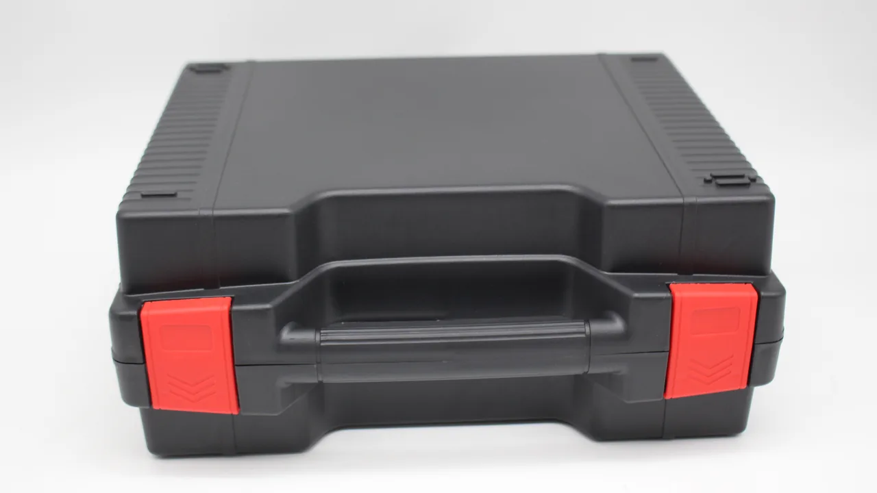
A stranding machine is one of the fastest and most balance-critical machines in cable manufacture. The bow — the curved arm that carries the wire around the cradle — spins at over a thousand revolutions per minute, is corrected on a balancing machine before dispatch, and normally leaves the works with residual imbalance measured in gram-millimetres. Let a bow pick up a slight bend or a local knock in transit, and vibration is amplified many times over once it runs: lay length becomes less consistent, and bearings and gearbox internals wear faster. The capstan carries the entire pulling force, and the profile accuracy of its grooves decides whether the cable tracks correctly or gets crushed. Gearbox shaft ends and couplings demand high coaxiality, and any shock shortens the life of the coupling's elastic elements. Transport packaging for these parts has to solve three problems at once — prevent slender curved parts from deforming, protect high-precision rotating fits, and deliver the balance data still valid on arrival.
JUNZHIJIA builds its protection principle for stranding machine components on three commitments: treat the bow as a quasi-metrological part, using shaped multi-point cradles to remove self-weight bow, soft overlays to remove local contact stress, and numbering plus test-run records to lock in the balance state; treat capstans and gearboxes as heavy precision parts, spreading load at structural nodes and protecting mating surfaces with cone sleeves and end caps. Three numbers decide whether the scheme worked: the free span of the bow, the feeler reading on capstan groove profile, and the deviation of the re-measured residual imbalance from the dispatch value. This article covers bows, capstans, gearboxes and cleanliness, with structural parameters, verification methods and arrival acceptance criteria.
Table of Contents
- Bow Dynamic Balance: How Residual Imbalance Creeps In During Transport
- Anti-Bow Support and Strap Positions for Long Curved Bow Arms
- Wire-Guide Groove Wear and Profile Accuracy Protection
- Preserving Plating and Grooves on Capstans
- Coaxiality Protection for Gearbox Shaft Ends and Couplings
- Matched Storage for Bow Bearing Housings and Pivot Pins
- Protecting Dismantlable Cradle Frames and Reel Seats
- Stiffness Verification and Multi-Point Support for Anti-Distortion Cradles
- Preserving Balance Tags, Counterweights and Test-Run Records
- Cleanliness and Foreign-Object Control for High-Speed Rotating Parts
- Case Humidity Management Combined with VCI Protection
- Balance Re-Test Before Re-Assembly and Document Handover
- Frequently Asked Questions FAQ
- Conclusion and Related Reading
Bow Dynamic Balance: How Residual Imbalance Creeps In During Transport
The bow is the most sensitive part on a stranding machine. It consists of two curved arms joined through a central structure, is typically 400–1200 mm long, and is inherently uneven in mass distribution. At the factory it is corrected by removing material or adding counterweights until residual imbalance falls inside the allowance. Three routes destroy that balance in transit. First, an arm bends elastically and does not fully recover, shifting the geometric centre by a fraction of a millimetre. Second, an end connection hole or pivot pin takes a local plastic deformation under impact, moving the effective axis of rotation. Third, a counterweight loosens or shifts, which is the most direct failure and the easiest to overlook.
The effect of residual imbalance grows with speed: doubling the rotational speed multiplies the centrifugal force by four for the same imbalance, because the force depends on the square of angular velocity. A bow that feels perfectly normal during a low-speed trial can vibrate violently at rated speed. Transport protection therefore cannot aim merely at "no visible damage"; the target is unchanged geometry, undisplaced counterweights and an unmoved axis of rotation.
In practice, the bow must be supported on the cylindrical section of its arms or on a reinforcement rib. Support points must never sit on a thin-walled arm section, on an end connection hole or on a counterweight mounting position, because all three deform easily and all three feed directly into balance. Contact material should be 25–35 Shore 00 IXPE or EVA, with a contact length of 1.0–1.5 times the arm diameter so unit pressure stays low. Before packing, re-check the tightening torque on every counterweight and mark each one with its number and mass, so that any movement can be detected on arrival.
| Source of imbalance | Trigger | Consequence | Measure |
|---|---|---|---|
| --- | --- | --- | --- |
| Elastic arm bend | Single-point support, mid-span strapping | Geometric centre shift | Shaped multi-point cradles, straps over supports |
| Plastic deformation at end holes | Lifting, dropping, stacking load | Axis of rotation displaced | End guards, never load-bearing |
| Counterweight shift or loss | Vibration, unchecked torque | Sudden imbalance increase | Torque re-check plus number marking |
| Surface knocks | Contact with hard objects | Local mass loss | Full-circumference soft wrap |
| Corrosion | Uncontrolled humidity | Mass change at balancing faces | VCI plus desiccant |
Anti-Bow Support and Strap Positions for Long Curved Bow Arms
The bow arm is a long, curved, thin-walled member: low bending stiffness, long span, and the damage it suffers in transit is usually not a dent but an overall change of curvature. Such a change may be only 0.3–1.0 mm, invisible to the eye, and yet enough to push the balance re-test outside the dispatch value. Preventing it means limiting the free span rather than adding straps.
Three rules govern support layout. First, keep the free span within 15–20 times the equivalent section diameter of the arm; where the arm carries a mid-length rib, the upper reference bound can be taken as twice the rib spacing. Second, support points must land on constant-section lengths or on ribs, never on a section transition, a weld joint or an end fillet, because all three are stress raisers. Third, the height difference between adjacent cradle faces must stay within 0.5 mm, or the packing itself applies a pre-bending load.
Strap position matters more than strap count. A strap belongs directly over a support point, pressing the arm into its cradle rather than pulling it into a curve. If a strap crosses mid-span, its tension applies a local bending moment and can leave a permanent set in the arm. Use 25–40 mm webbing with soft pads where it meets the part, and judge tension by pressing the webbing: 3–5 mm of sink is right. Bows longer than 800 mm need at least two straps, symmetrically placed. On a twin-arm bow, support each arm independently; never run one strap across both arms, because it draws them towards each other and changes the opening dimension of the bow.
Wire-Guide Groove Wear and Profile Accuracy Protection
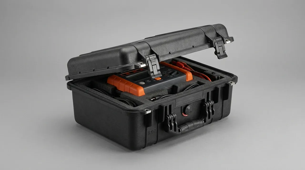
Wire guides are densely distributed around a stranding machine, typically 60–200 mm in diameter with V-shaped or U-shaped rope grooves through which the cable runs at high speed. The groove profile sets the contact pressure distribution and the tracking position: once a groove carries a burr or a local depression, the cable is scored or jumps out of the groove, and in the worst case the line stops with a break. The usual transport injuries are guides knocking against each other and groove edges rolled by contact with heavy metal parts.
Store guides on the principle of one size per pocket, no rim contact. Cut a half-round pocket to each guide diameter so each unit sits in its own place with no rim touching a neighbour. Where many guides share one case, use layers separated by rigid dividers, with pockets offset between layers so no upper guide sits directly on the groove of the one below. Grooves themselves can be temporarily covered with a soft guard ring or a low-tack protection film; keep the guard bore slightly larger than the groove root so the guard never becomes a load point.
Bearings inside the guides need protection too. Most are small deep-groove ball bearings, and at high speed they are very sensitive to raceway condition. Fit soft plugs at both ends of the bore to keep dust out, and fit caps over grease nipples or seal covers so a nipple cannot snap off in an impact. Carry a guide by its body, never by its groove; finger pressure on a groove edge is enough to leave a mark that shows up later as cable scuffing.
Preserving Plating and Grooves on Capstans
The capstan is the end of the drive chain on a stranding machine: typically 300–800 mm in diameter, with a hard-chromed or hard-faced surface turned with several parallel pulling grooves. Damage to that surface cuts both ways. Groove wear changes the pulling-force distribution and lets the cable slip, while a break in the plating spreads corrosion outward from the break in a humid environment. Transport protection has to solve "no knocks to the surface" and "no squeezing of the grooves" at the same time.
Structurally, the capstan should bear on its hub or an end face, with the rim and groove area carrying nothing. Laid horizontally, clamp the hub between two full-face boards or support it on a soft saddle matched to the hub diameter. Stood vertically, which large capstans often require, it needs a continuous base rather than two contact points on the rim. Never stack capstans directly on one another; always interpose a divider and soft padding, and where stacking is unavoidable, the upper capstan must be carried by the divider, not resting on the rim of the one below.
Temporary groove protection works well as non-woven wrap plus a PE film overwrap, wound circumferentially along the groove direction so no non-woven edge lodges in a groove and forms a hard point. On hard-chromed surfaces, chloride-bearing solvents, wire brushes and abrasive paper are all prohibited; light rust is best removed with a dedicated stainless cleaner and a soft cloth. Capstans are heavy, so sling them with protected webbing around the hub, never with a hook on the rim or in a groove. Supporting and lifting principles for large rotating bodies transfer directly, as set out in Hydro Turbine Component Cases: Transport Protection for Runners and Guide Vanes.
Coaxiality Protection for Gearbox Shaft Ends and Couplings
The gearbox on a stranding machine connects to the capstan and to the bow spindle through couplings. Its output shaft end is usually a taper or a keyed cylinder, and the coupling may be elastic or of the gear type. This group of fits sets the coaxiality and the vibration level of the whole drive train: once coaxiality is disturbed, the coupling's elastic elements see extra alternating load and fatigue early, while vibration passes into the gearbox and accelerates gear and bearing wear.
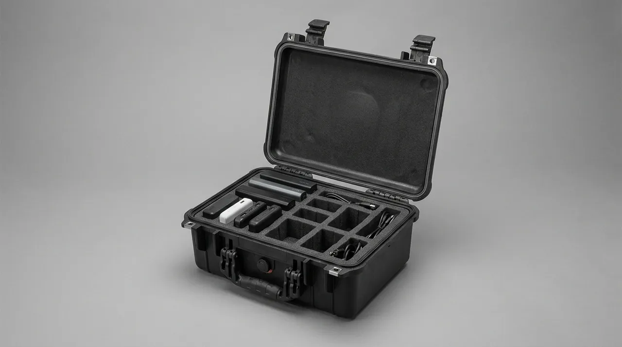
The core rules are that the shaft end carries no load, the keyway carries no pressure, and the taper touches nothing. The shaft end must never serve as a support point or a lifting point, so the packing must give the gearbox housing its own feet and a surrounding location frame. A keyed shaft should be wrapped in non-woven before it enters its locating block, and that block must not locate on the keyway. The taper needs a soft cone sleeve with clearance to any hard structure. If the coupling can be removed, pack it separately and mark both phase and fit references on the shaft.
Treat the gearbox itself as a precision item rather than a box. Fit soft caps to both input and output ends, support the feet on soft pads, and add location blocks on all four sides to stop movement. Check that the oil sight glass is tight, and if necessary drain or reduce the oil charge before shipping so surge does not push past the seals or churn into heat. If the gearbox breathes through a vent, plug it temporarily or convert it to manual relief so rain and dust cannot enter. Taper and bearing fit protection follows the same logic as CNC Spindle Cases: Transport Protection for Spindle Tapers and Bearings.
Matched Storage for Bow Bearing Housings and Pivot Pins
Bow bearing housings and pivot pins are small, expensive parts: housing bores are held to tight tolerance, mounting positions are precise, and the clearance between pin and bore governs how accurately the bow rotates. The biggest risk in transit is not impact but loss of the pairing relationship. Once parts from several machines are mixed, the fitters must measure each combination on site, which costs time and invites wrong assembly.
Use one set per pocket, one pocket per drawing. Put each bearing housing together with its pivot pin, shims and fasteners in a single pocket and print the machine position number beside it. Paste a layout drawing inside the lid listing position number, part name and quantity. Wrap the fit section of each pivot pin in non-woven before inserting it into its locating hole, and let neither pin head nor pin tail carry any load. Plug housing bores with soft bungs to exclude dust, apply a PE film to mounting faces, and list the film removal step.
If parts ship in batches, deliver the pairing marks and layout drawing with the first batch, so the second batch is not left without labels. For export projects, print position numbers in both Chinese and English and add material and heat-treatment columns to the packing list for customs and incoming inspection. Selection and failure logic for comparable small mechanisms is covered in High-Strength Case Hinges: Structure, Load Capacity and Failure Diagnosis.
Protecting Dismantlable Cradle Frames and Reel Seats
Cradle frames and reel seats on a stranding machine are large welded or bolted structures with an uneven stiffness distribution, usually carrying removable hinges, pins and limit blocks. The characteristic failure in transit is angular distortion with an excessive diagonal length difference. Once the frame twists, reel-seat levelness and the coaxial relationship between the two ends are both lost, and the reel surges axially during stranding, which degrades lay-length consistency directly.
Three principles apply: support at nodes, close the load path, and prefer dismantling. Supporting at nodes means that every cradle or block is set under a structural node rather than at the middle of a member. Closing the load path means bracing the frame to the case with adjustable struts or timber blocks so the load path runs case–strut–frame, rather than relying on strap tension to hold the shape. Preferring dismantling means packing column, beam, reel seat and tension arm separately with assembly numbers and phase marks preserved.
For a one-piece cradle frame that cannot be dismantled, weigh horizontal against vertical packing. Horizontal packing needs a continuous load-bearing base under the frame, and the long axis of the frame should follow the long axis of the case so emergency braking does not create a tipping moment. Vertical packing needs side bracing and a continuous base as well. Either way, measure both diagonals before dispatch and repeat the measurement on arrival in the same support condition; a difference above 3 mm counts as an anomaly.
Stiffness Verification and Multi-Point Support for Anti-Distortion Cradles
The anti-distortion cradle is the key structural element in bow and cradle-frame packaging, and if the cradle itself lacks stiffness every downstream measure fails. Cut cradles from high-density EVA at 60–90 kg/m³. Where the span exceeds 600 mm, embed an aluminium profile or plywood skeleton and hold the cradle's own deflection within 1/500 of its span.
Verify in sequence: establish part mass and centre of gravity; set the number and spacing of support points; calculate cradle loading under the worst case, normally 1.5 g vertical and 1.0 g lateral; then check the compression and overall deflection of the cradle material under that load. Compression should stay within 2 mm; more than that means the material density is too low or the contact area too small. Across a set of load-bearing cradles, keep the load variation within ±15 %, because otherwise the most heavily loaded cradle crushes first.
More support points are not automatically better. Too many increase assembly time and make height control difficult, introducing new error; too few leave the free span unconstrained. Practical guidance is to set the minimum number of supports from the rule that free span must not exceed 15–20 times the equivalent diameter, then add supports according to part shape and centre of gravity. Trial-fit every cradle before it goes into the case, confirming the part drops in without force. Cradle material choice is itself a weight-versus-stiffness trade-off, discussed in Case Weight and Strength Balance: Wall Thickness, Material and Structure Trade-offs.
Preserving Balance Tags, Counterweights and Test-Run Records
The balance state of a bow is its most valuable intangible asset, and the information most easily lost in transit. The factory normally records initial imbalance, the correction method — material removal or weight addition — residual imbalance and test speed. That data must travel with the part and be fixed inside the case in a waterproof document pouch, protected from humidity and handling.
Three physical measures matter. First, re-check counterweight tightening torque and apply a locking method such as thread adhesive or a lock washer, then mark each weight with its number and mass so movement or loss can be detected item by item on arrival. Second, apply corrosion protection to the balancing faces — the drilled or milled areas where material was removed — and cover them with a protection film, because exposed substrate at those spots corrodes first and corrosion changes local mass distribution. Third, preserve the phase mark from the balancing run, usually struck on the shaft end or hub, with an oil-resistant marker or an engraved line; adhesive tape labels fall off.
On the paperwork side, ship a balance record and a counterweight list with the case, and add a separate line to the packing list confirming that the balance documents are enclosed. On arrival, read the documents first and then check the physical parts against the counterweight numbers. If a weight has moved or a balancing face has corroded, photograph it with the packaging still intact and re-test balance before deciding whether to install.
Cleanliness and Foreign-Object Control for High-Speed Rotating Parts
Rotational speed sets the cleanliness requirement. A bow turning at over a thousand revolutions per minute throws off anything adhering to it: at best the cable surface is contaminated, at worst wire guides and guards are struck. Three classes of foreign object enter during packing — liner debris from low-density foam, fibre from packaging materials such as board and non-woven, and dropped tools including screws, tie tails and blade fragments.
Control spans materials, working practice and closing. For materials, liners must be closed-cell — IXPE, EVA or high-density PU — and bare expanded polystyrene and loose foam beads are banned. Paper filling should be avoided; where it is essential, wrap it completely in PE film first. For working practice, isolate the packing area from other assembly work, issue and collect tools against a counted list, and inspect grooves, flights and internal cavities with a torch and borescope before the lid goes on. For closing, all tape and labels stay outside the case; nothing loose may remain inside.
Parts that have already run need their oil film and cable debris removed before packing. Oil traps dust into clumps that settle at groove roots and are hard to remove on arrival. Wipe with a neutral cleaner and a soft cloth, never with a pressure washer, which drives water into bearings and gearboxes, then dry and apply a thin volatile corrosion inhibitor.
Case Humidity Management Combined with VCI Protection
Stranding machine parts are mostly alloy steel, some with hard chrome or a nitrided layer, and all are sensitive to humidity and chloride. Sea freight, rainy-season road transport and open port storage all drive humidity inside a case upward quickly, and once relative humidity passes 60 %RH a water film forms on steel and the corrosion threshold is crossed. Controlling case humidity is the first and cheapest anti-rust measure.
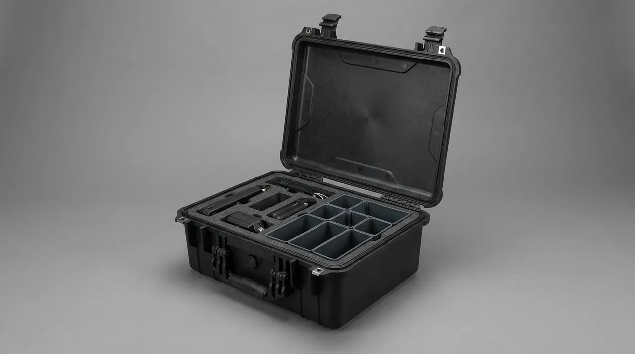
Match the desiccant mass to the air space left inside the case — roughly two to three grams of silica gel for every litre of free volume, or a lower mass if a molecular sieve is chosen instead. For reusable cases, prefer silica gel that can be regenerated in an oven and replace it after every return leg. Suspend or fix the desiccant to the inside of the lid so it never touches the parts, and fit a reversible humidity indicator card with a 40 %RH threshold. Design the enclosure to IP65, and where sea freight or open storage is involved, raise it to IP67 with a pressure-equalisation valve using a waterproof breathable membrane.
VCI and desiccant work best together: the desiccant holds ambient humidity down while the inhibitor forms a molecular adsorption film on the metal, so a brief humidity excursion still does not start corrosion. Two cautions apply. Surfaces must be clean and dry before treatment, because oil blocks adsorption. And the compatibility of the inhibitor with copper and zinc must be confirmed; cases holding copper cable components need a multi-metal VCI formulation. For sea freight and long storage, log both temperature and humidity inside the case at ten-minute intervals; that record then serves as objective evidence during acceptance and any subsequent claim.
Balance Re-Test Before Re-Assembly and Document Handover
On arrival, the most important step is not immediate installation but a balance re-test and document check. Work through it in order. Inspect the case exterior, seals and humidity indicator card to confirm that no obvious moisture ingress or impact occurred. Open in pocket order and tick the packing list item by item, focusing on whether counterweight numbers match the list and whether anything has moved or fallen off. Then carry out a geometric check: bow curvature in the free state, roundness of the end connection holes, capstan groove profile, and the diagonal length difference of the frame. Finally, before installation, re-test balance and compare residual imbalance with the dispatch value.
Suggested acceptance limits: residual imbalance must not exceed 120 % of the dispatch value. Between 120 % and 150 %, correct it on site by trimming or adding counterweight and log the correction. Above 150 %, stop installation and ask the supplier to investigate. In parallel, re-measure bow curvature in the free state, using a surface plate with a feeler gauge or a laser, and check capstan groove profile with a template or feeler; these two measurements help explain where the imbalance came from.
For document handover, archive the balance record and re-test result, the packing list and layout drawing, the humidity indicator card reading and logger data, unpacking photographs, and any anomaly report. That file is decisive in later warranty and claim discussions.
Frequently Asked Questions FAQ
Q: The bow looks completely normal after transport. Do we still need to re-test the balance?
A: Yes, and the reason is that a bow typically bends by only 0.3–1.0 mm, which neither the eye nor the hand can reliably detect, while the effect of residual imbalance on vibration rises with the square of rotational speed. A bow that behaves perfectly during a low-speed trial can shake violently at rated speed, and by then the bearings are already taking the load. Re-test before installation and compare the residual imbalance with the dispatch value using three bands: within 120 % of dispatch is normal; between 120 % and 150 % can be corrected on site by trimming or adding counterweight, with the correction logged; above 150 % means stop and ask the supplier to analyse. While the bow is off the machine, also measure free-state curvature and the roundness of the end connection holes, because both point to where the imbalance came from and both support a later claim. Log the re-test result next to the dispatch figure on the same record sheet, so that a trend becomes visible if the same bow ships more than once.
Q: How should the bow be supported, and can a strap cross the middle?
A: Support layout follows three rules. Keep the maximum free span within 15–20 times the equivalent section diameter of the arm. Place supports on constant-section lengths or on ribs, never on a section transition, a weld joint or an end fillet. And keep the height difference between adjacent cradle faces within 0.5 mm. A strap must never cross mid-span: tension at that position applies a local bending moment and can leave a permanent set in the arm, which then shows up as imbalance. Place every strap directly over a support point so it presses the arm into its cradle. On a twin-arm bow, support the arms independently and never run one strap across both, because that draws them together and changes the opening dimension. Judge strap tension by pressing the webbing; 3–5 mm of sink is about right. Check that the cradle faces are free of butt joints as well, because a joint edge under a strap prints a line into the arm, and re-check strap tension after the first few hundred kilometres of travel, since webbing relaxes once it has settled into its load.
Q: A wire-guide groove has picked up a burr. Can we dress it with a file on site?
A: Dressing it with an ordinary file is not advisable, because hand filing rarely restores the arc of the groove and tends to create a local flat that concentrates cable contact pressure instead of relieving it. If the burr is tiny and sits on a groove edge outside the contact zone, the original manufacturer can dress it with a fine oilstone worked in one direction along the groove, then verify the profile with a template or feeler and measure runout at that point. If the burr sits at the groove root or on a contact flank, replace the guide, because any profile deviation is amplified at high line speed into cable vibration and scuffing. To prevent it, store each guide in its own half-round pocket with no rim-to-rim contact, cover grooves temporarily with a soft guard or low-tack film, and carry guides by the body rather than by the groove. Guides that have already seen service should be examined for existing wear before packing, so that wear present beforehand is not attributed to transport afterwards.
Q: Should a capstan groove surface be protected with oil or with film?
A: Use film rather than oil. A capstan groove is the direct contact surface for the cable, and any grease left on it transfers to the cable and causes poor adhesion in later operations such as printing or jacket extrusion. The correct method is to wrap non-woven circumferentially and overwrap with PE film, winding along the groove direction so no non-woven edge lodges in a groove and forms a hard point. If corrosion is a concern, spray a very thin volatile corrosion inhibitor before wrapping, targeting a 1–3 μm film, rather than brushing on anti-rust grease. On hard-chromed surfaces, chloride-bearing solvents and wire brushes are prohibited; light rust is best treated with a dedicated stainless cleaner and a soft cloth, after which the protective film is renewed. Where a capstan is stood vertically, check the base for flatness first, because a wavy floor transfers a bending moment into the rim. If the plating already has a break, mark it, photograph it and record its location, since corrosion spreads from such a break during a humid voyage and the mark makes it possible to show that the break predates dispatch.
Q: How should the gearbox shaft end be protected, and should the coupling come off?
A: The output taper or keyed cylinder must carry no load, the keyway must take no pressure, and the taper must touch nothing. Give the gearbox housing its own feet and a surrounding location frame inside the case so the shaft end never becomes a support or a lifting point. Wrap a keyed shaft in non-woven before it enters its locating block, and make sure the block does not locate on the keyway. Cover the taper with a soft cone sleeve that has clearance to all hard structures. If the coupling can be removed, take it off and pack it separately, marking both phase and fit references on the shaft; that keeps shock away from the coupling and simplifies re-assembly. Also cap both gearbox ends, check the sight glass for tightness, and drain or reduce the oil charge if surge through the seals is a risk. Where the gearbox carries a cooling fan or a belt pulley, remove it and pack it separately, because an overhung mass multiplies shock loading on the shaft bearing during transport.
Q: How do we tell whether a cradle frame has distorted, and where should supports go?
A: The most direct criterion is the diagonal length difference. Measure both diagonals before dispatch and repeat on arrival at the same temperature and on the same supports; a difference above 3 mm indicates angular distortion. Also check reel-seat levelness and the parallelism of the two columns, since a twisted frame shows up in both. A cradle or block should always sit under a structural node — the foot of a column or the point where a beam meets a column — and never at the middle of a span, since a central prop simply lets the member sag between its two contact points. Restraint is then completed by tying the frame back to the case through struts or timber, creating a case-to-strut-to-frame load path; strap tension alone must not be trusted to preserve geometry. Straps only limit horizontal movement and prevent tipping; they are not torsional members. If the frame must ship as one piece, fit temporary diagonal braces across the frame opening, because a diagonal brace carries shear far more effectively than webbing and costs little to add. Record the brace positions on the layout drawing so they are removed in the correct order at the destination.
Q: Why is cleanliness more critical for high-speed parts than for general machinery?
A: Because centrifugal force turns any adhering object into a projectile. A bow turning at over a thousand revolutions per minute throws off whatever is stuck to it; at best the cable surface is contaminated, and at worst wire guides and guards are struck. Debris lodged in a groove also acts as an abrasive, scoring the cable continuously at line speed. Packing therefore has to control three classes of foreign object: liner debris, packaging fibre and dropped tools. Use closed-cell liners and ban bare expanded polystyrene and loose foam beads; isolate the packing area from assembly work; issue and collect tools against a counted list; inspect grooves, flights and cavities with a torch and borescope before closing; and keep every tape and label outside the case. Parts that have already run should be degreased and cleared of cable debris first. Debris already thrown inside the machine is harder to find than debris left in the case, so a final inspection with the guards removed is worth the time on any strander that will run above a thousand revolutions per minute.
Q: What should be checked before re-assembly after delivery?
A: Work in four steps: appearance, list, geometry, balance. First inspect the case exterior, seals and moisture traces, and read the humidity indicator card and logger data. Second, open in pocket order and tick the packing list item by item, concentrating on whether counterweight numbers match the list and whether any weight has moved or fallen off. Third, perform the geometric checks: bow curvature in the free state, roundness of the end connection holes, capstan groove profile and the diagonal length difference of the frame. Fourth, re-test balance before installation, treating a residual imbalance within 120 % of the dispatch value as normal, correcting and logging anything between 120 % and 150 %, and stopping installation above 150 %.
Conclusion and Related Reading
Bow balance, groove profile and shaft coaxiality decide whether a strander restarts on schedule. JUNZHIJIA supplies shaped multi-point cradles, node supports, sub-40 %RH packing and OEM/ODM tooling for stranding machine builders.
Related Reading