

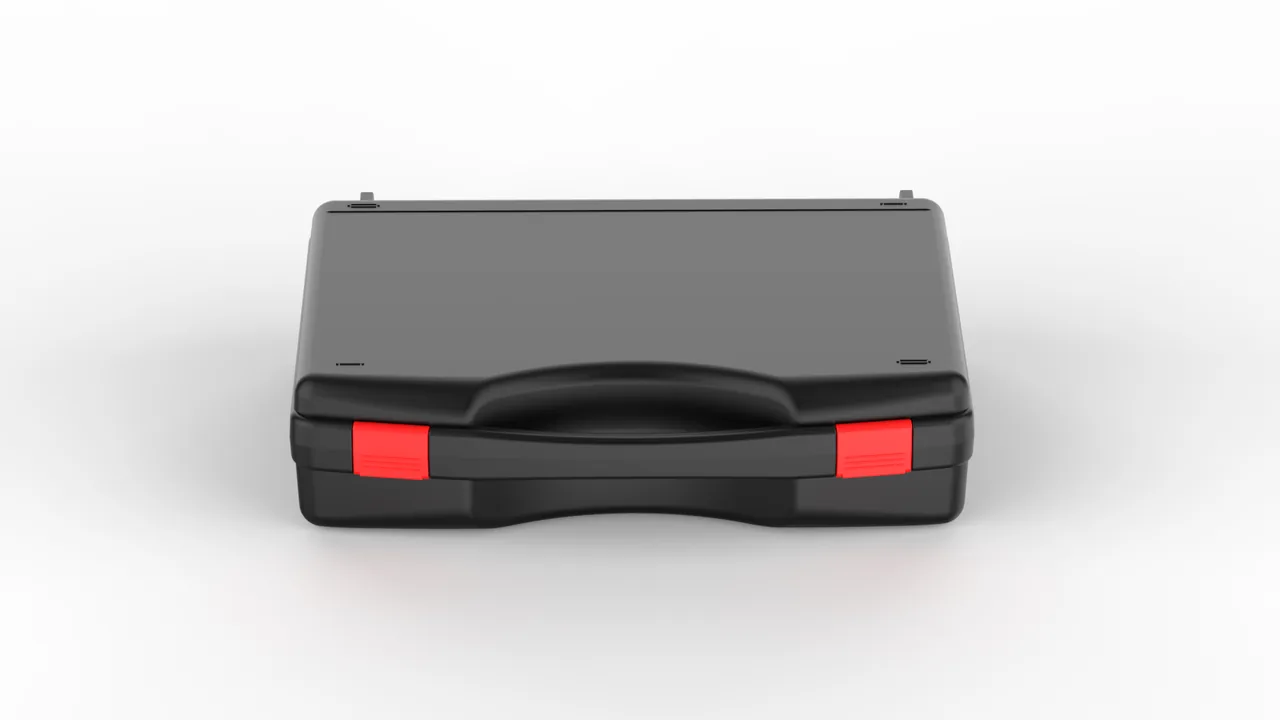
On sludge dewatering, mineral concentration, chemical slurry separation and oil sludge treatment lines, an overhaul of a decanter centrifuge rarely means shipping the whole machine. Instead the drum, the bow screen, the bearing housings and the screw conveyor are removed and shipped in separate batches. The drum is a long conical shell weighing anywhere from several dozen to several hundred kilograms, with the decanter shaft passing through bearings at both ends and the flight strip welded inside. The bearing housing is the opposite proposition: a short, massive cast iron or forged steel body whose bore carries a matched set of thrust bearings and oil thrower rings. Packaged together in a single case, the failure mode is rarely a dent or a broken corner. It is that the balance is destroyed somewhere between the loading bay and the commissioning floor, and the retest on site fails.
JUNZHIJIA treats these parts as what they actually are, a precision rotating element and a heavy structural element at the same time. The drum must sit on a balance bracket dimensioned from measured centres of gravity, with loading direction constrained by hardware. Bearing housings get their own sealed compartment where corrosion protection outranks impact protection. The bow screen never shares a case with heavy castings; it is packed separately against blockage and deformation. The whole principle reduces to one sentence: a parts case does not merely enclose the component, it preserves the component's rotational precision right through to the moment of the final retest.
Table of Contents
- Balance Grades for the Drum and the Consequences of Residual Imbalance
- Diagnosing Bow Screen Blockage and Packing It for Cleaning
- How Screw Outer Diameter Clearance Wear Destroys Separation
- Bearing Housing Concentricity Errors and the Temperature Rise They Cause
- Main Bearing Clearance and the Grease Recharge Window
- Cone Shell Welds and Transport Stress in Long Conical Sections
- Cleaning Timing for Dried Slurry Residue and Packing Timing
- Balance Bracket Assembly and Load Restraint for the Drum
- What Vibration Levels Demand from Case Structure and Fasteners
- Compartment Layout: Fitting Drum, Screen and Housings into One Case
- Humid Heat Cycling, Salt Spray and Long-Term Storage
- Site Acceptance: Rebalancing and Clearance Re-Verification
- Custom Process and Packing Documentation
- Frequently Asked Questions FAQ
- Conclusion and Related Reading
Balance Grades for the Drum and the Consequences of Residual Imbalance
The single most valuable attribute a stripped drum still carries is its residual unbalance. Under ISO 21940, mirrored in China by GB/T 9239, a high-speed rigid rotor such as a decanter drum is normally specified to G6.3 through G2.5, and the common workshop acceptance method is two-plane balancing on two supports, expressed as a permissible residual unbalance converted to equivalent eccentricity. The exact figure depends on rotor mass and speed. The transport obligation is direct: if the mounting arrangement inside the case lets the drum deform plastically, lets the calibration weights relax, or transfers the mass that was previously balanced away into the friction pads and seal strips, the site retest has nothing left to verify.
Imbalance damage is a chain, not an event. Once rotational speed crosses into a range where drum excitation frequency approaches a structural resonance of the bearings or the case, amplitude builds within seconds. Dynamic bearing load grows with the cube of that amplitude under the L10 life model, so a thrust bearing set specified for several thousand hours can show raceway spalling within a few shifts. Vibration travels along the cone shell, cyclic stress rises at the welds, and the roots of the wedge-shaped screen bars become the most likely crack initiations. Worse still, concentricity between housing and main shaft is progressively destroyed by early bearing failure, so the eventual repair costs far more than the transport damage did.
JUNZHIJIA therefore treats three items as non-negotiable in any drum case. First, three or four support points, positioned close to the balancing planes rather than wherever the shell happens to be convenient. Second, marked loading direction plus a mechanical restraint so the drum can never be lifted or set down on a side face or left cantilevered at the nose. Third, a record made before sealing of every support pad number and weight position, carried in the documentation pack so the site team can verify rather than assume.
| Disturbance case | What the site sees | Root cause | Packaging response |
|---|---|---|---|
| --- | --- | --- | --- |
| Support pad crushes shell | Retest unbalance high, arc-shaped impression | Foam too soft, no rigid spreader | Rigid locating pad plus replaceable wear pad |
| Balance weight migrates | Single-plane residual unbalance jumps | No mechanical lock | Clamp plate and lock bolt, position scribed |
| Case resonates | Noise in transit, fasteners loosen | Stiffness and frequency not separated | Raise compartment stiffness, retune damping layer |
| Thrower ring strikes journal | Bright patches, grease film worn through | Unrestrained axial travel | End stops with retained axial clearance |
Diagnosing Bow Screen Blockage and Packing It for Cleaning
The bow screen is the part most often destroyed in transport, and the mechanism is stiffness rather than strength. The screen is an arc-shaped plate assembled from wedge wire bars set at a precise slot pitch and welded together. Slot widths commonly fall between 0.2 and 0.5 mm, and their function is to retain solids against the outer face while liquid passes through. Freed from the restraint of the cone shell, that arc plate is fundamentally a thin shell, and any concentrated load distorts it, turning an array of precisely parallel slots into a pattern of crushed fish-eyes.
Blockage has three distinct causes, and each demands a different response. The first is filtered-residue blockage: cake, mineral crystals and polymer gel form a hard crust inside and across the slots and dry into something with the consistency of glue. These must be cleaned with a soft brush and low-pressure water pushed from the smooth back face outward, never probed with a steel wire, because debris driven into the wedge root deforms the bar. The second is dried slurry residue, where soluble salts and oil sludge precipitate after shutdown; these respond to warm water with a neutral detergent, then low-pressure rinsing. The third is embedded foreign matter such as tangled fibre, strap fragments and seal debris, which must be picked out one piece at a time, followed by a full slot inspection for root cracks.
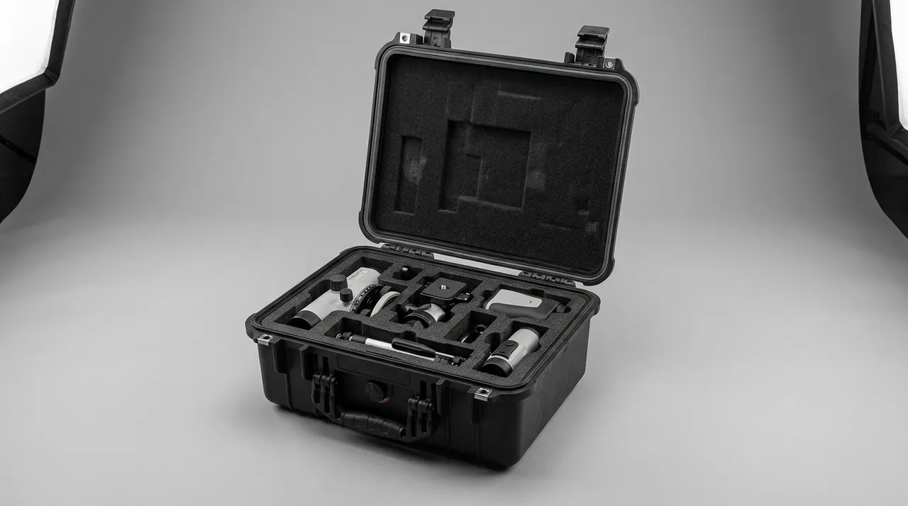
Packing responds with a separate compartment and a separate liner. The arc plate stands on edge rather than lying flat, because flat placement lets its own weight close the slots at mid-span first. Thin, uniform perforated foam is applied to both faces so contact pressure spreads across the whole plate instead of concentrating at a few points. Finger-loop extraction tapes are left at the perimeter so the plate can be removed at site without inverting the case. The compartment principle follows the same logic used in Vibrating Screen Cases: Vibrator & Deck Frame Component Protection, but the decanter screen has a far smaller permissible deflection. Keeping the screen out of the heavy-parts case also prevents a weighty casting from bearing down on it, and prevents desiccant dust from settling on the filtering face.
How Screw Outer Diameter Clearance Wear Destroys Separation
Separation efficiency in a decanter depends heavily on the clearance between the screw flight outside diameter and the cone shell inner wall. The design arranges for tight clearance at the discharge end and wider clearance in the thickening zone, creating a progressive concentration zone where solids are thrown outward and conveyed forward. After service, hardfacing on the flight outer edge develops hollows while the shell wall is gouged into grooves by solid particles. Combined, the practical clearance ends up several times the design value, and the machine keeps turning and keeps discharging mud while separation has quietly stopped working.
Three diagnostic paths confirm the condition. First, torque: a clear rise in screw drive motor current means the resistance to advancing solids has grown, which normally means the flight is contacting or approaching the shell. Second, cake solids concentration falls and the overflow runs thinner, because solids are no longer being concentrated but are leaving with the liquid. Third, a regular helical wear band appears on the shell wall with a step you can feel by hand.
Packaging cannot prevent wear, but it can prevent the worn state from being damaged a second time and can keep the data honest. Both ends of a dried screw must be fitted with rigid end covers so that axial shock in transit cannot drive the flight edge into the shell again. Where screw and shell travel together, a reliable separator must sit between them rather than allowing contact. JUNZHIJIA records the measured flight diameter and shell pairing number, and ships a clearance record card inside the package so the site retest can reference the same pairing, separating wear accrued in service from damage added in transit. The same discipline of recording, isolating and re-verifying a wear clearance appears in Pump, Valve & Fitting Cases: Impeller, Body & Flange Protection, where impeller-to-casing clearance is treated as a controlled parameter rather than an incidental dimension.
| Clearance condition | Measured flight diameter | Operating behaviour | Recommended action |
|---|---|---|---|
| --- | --- | --- | --- |
| New design condition | 100% of design clearance | Cake solids on target | Baseline reference |
| Light wear | Increased 10–20% | Slight solids escape | Record baseline, keep monitoring |
| Moderate wear | Increased 30–60% | Solids down clearly, torque up | Hardface repair or replace screw |
| Severe wear | More than doubled | Separation failed, cone blockage | Assess the drum as a whole |
Bearing Housing Concentricity Errors and the Temperature Rise They Cause
The main bearing housing is the most sensitive component on the machine. Its bore has to form line or surface contact with the main shaft journal, achieved through a set of precision cylindrical or spherical rollers working against a thrust bearing, and the preload and clearance of that whole set depend on the concentricity of the housing bore and the flatness of its axial locating face. The classic transport damage pattern is a housing seated on foam inside a compartment, where the foam creeps under prolonged vibration and the loaded case distorts the bore, changing a dimension that was fully acceptable at the factory.
The relationship between that error and temperature is predictable. Radial non-concentricity redistributes roller loading around the circumference, raising local raceway contact stress, accelerating roller spin and pushing bearing temperature beyond the grease drop point within two hours of commissioning. A locating-face flatness error magnifies axial wander instead, so the oil thrower and seal lip rub repeatedly, the grease film thins, and dark oily sludge appears at the seal. Field reports describe a housing running 20–30 °C hotter than its peers, black sludge at the seal, and slight creep on the bearing outer ring, and the true cause is often a transport event three months earlier.
The response is therefore specific: an independent compartment per housing, cavity dimensions opened to the measured part plus a defined clearance, with foam never used as the locating surface. Support comes from a rigid locating platform with replaceable wear pads, while foam serves only on non-load-bearing faces for buffering and moisture isolation. Corrosion encapsulation is applied as detailed later in this article, lifting eyes and vertical-lift markings are provided, and bore roundness plus locating-face flatness are measured with an indicator before sealing, with those values entering the documentation pack. The precision-fit and grease protection methods used in Bearing & Gearbox Cases: Precision Fit Surface & Grease Protection apply here, but a decanter housing adds two risks those do not cover, namely cone shell load transfer and thrower ring interference.
Main Bearing Clearance and the Grease Recharge Window
Clearance in a decanter main bearing is not a quantity where more is better. Too little and load shock arrives directly at the rolling elements, producing early pitting and plastic deformation. Too much and the shock is absorbed, but film stability degrades, soap-base grease is flung out at speed, and the resulting grease loss becomes self-reinforcing. Normal practice is to select one manufactured clearance class from speed and load, then sort by measured value during reassembly and retest once more after a running-in period.
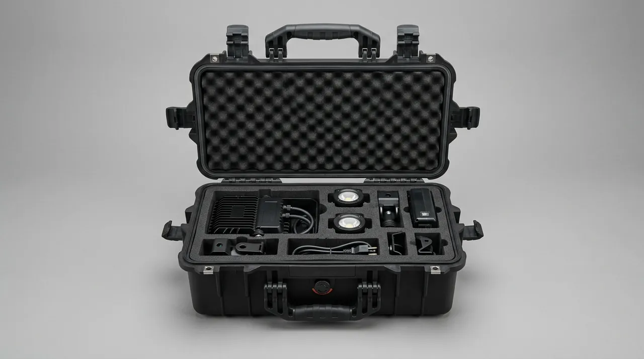
Packaging design has to accept a practical reality: the bearings are usually assembled and greased before shipping, already protected by corrosion film or a seal, so a site that lifts the set straight from the packaging into the housing has defeated the packaging entirely. Two configurations therefore need different treatment. Where the bearing set is already fitted in the housing, the case must protect the assembly relationship and keep the locating face out of any load path, so the press-fitted bearing is never shoved or rocked. Where bearing and housing ship separately, each needs independent corrosion encapsulation and axial restraint, and the documentation must state plainly that site assembly requires clearance to be measured again and grease to be charged again rather than trusting the pre-transport record.
Grease charge limits belong in the documentation as well. Quantity follows from bearing bore and speed, and both the grease inlet and the drain path must be identified before sealing, because many decanter housings drain through the housing floor where transport debris can lodge. Mixed and spent grease must be purged through a clean access window rather than topped up indiscriminately. These items look trivial on paper, yet they are the most frequent root causes behind temperature complaints in the first months of operation.
| Check item | Method | Acceptance criterion | Consequence if out of spec |
|---|---|---|---|
| --- | --- | --- | --- |
| Radial clearance | Indicator pushing the outer ring | Matches selected target within assembly tolerance | Early spalling or excess temperature |
| Axial clearance / wander | End screw displacement | Within permitted wander, no binding | Thrower wear, seal leakage |
| Grease charge | Metered gun or mass difference | Within 5% of calculated value | Dry pitting on low charge, heat and purge on overcharge |
| Drain path | Full-length rod check | No dried residue in the passage | Grease pressure trapped in the cavity |
Cone Shell Welds and Transport Stress in Long Conical Sections
A decanter drum shell is welded from multiple cylindrical and conical sections, which makes the weld line not merely a structural detail but a carrier for both residual stress and balance. Uneven heat input creates local stress concentration in the cone transition, and when vibration stresses from transport superimpose on that, microcracks can initiate near the fusion boundary. Once a weld shows geometric deviation, the rotor's balance has effectively been redefined, and an unbalance figure that passed before loading no longer holds.
Long conical sections carry a specific transport risk in addition: rattle response. As a vehicle crosses seams, speed humps or uneven pavement, the drum makes small jumps inside the case and its contact points switch repeatedly, so shock stops being broadband and random and concentrates at a few defined locations. Without restraint, the drum can migrate along the case axis until it strikes the end cushion, and that repeated impact is a credible route to weld fatigue cracking. The response is a replaceable restrained stop at the case end, designed with 10–20 mm of clearance, so the case wall and the stop together limit longitudinal travel while three-point supports continue to define lateral position precisely.
Case design for long parts follows from this. Lateral bending stiffness must exceed longitudinal stiffness, because cornering side acceleration is the dominant load in transit. Support pads must land on reinforced sections such as flange rings and bolt seat rings, never on thin wall. And external ribs must align with the support pad positions, so the panel cannot deform before the part does.
Cleaning Timing for Dried Slurry Residue and Packing Timing
Slurry fed to a decanter may be high-solids sludge, mineral pulp, chemical slurry, oily sludge or polymer-flocculated sludge, and any residue shipped inside the case causes two distinct problems. First, it absorbs moisture, dries and expands, which can push the bow screen out of its arc and form a hard shell bonded to the case interior. Second, acidic or alkaline carryover keeps attacking the cone shell, the screen and the bearing housings even during a few weeks of storage.
Cleaning timing has to sit between two fixed points. The first wash must be completed at the strip-down site; no part may be packed with product still in it. And packing must happen before the residue has a chance to re-dry into a hard crust. Field practice is hot water or a low-pressure lance with neutral detergent, concentrated on the mating faces between flight edge and shell wall, both faces of every screen slot, and the housing bore. Where washing will not reach, leave a disassembly mark rather than forcing a tool, and record the part as delivered with product so the customer understands the limitation is not something the case can solve. The insistence on clean, strippable residue mirrors the cake-release requirements described in Filter Press Cases: Plate & Hydraulic Closing Protection, where residue hardening in transit turns a routine unpacking job into a stripping job. The packaging-readiness test itself is simple and can be checked by the site team: no free-flowing residue, no crust, no tack on finger contact, and no sour or rancid odour. All four pass, and rust protection plus sealing may begin. For parts that will sit outdoors or on site for weeks, add one drying stage before sealing, using low-temperature forced air or natural ventilation until fully dry. Sealing a damp part traps the moisture instead of protecting against it.
Balance Bracket Assembly and Load Restraint for the Drum
The balance bracket is the one element in the case that has to be built per part. It is not a generic tray but a support point system matched to the drum as it actually exists: pad locations must clear the bow screen, the weld heat-affected zones, and the weight blocks and their tapped holes. Pad hardness has to be chosen between not denting the cone shell and not printing an indentation into it, which normally means a replaceable engineering polymer pad or an elastomer pad over a stainless core. Support span works the other way: a wide span reduces cone shell flexure in transit, while a narrow span complicates pad count and weight verification. Every one of those trade-offs is resolved from measurement, not from a drawing assumption.
Two actions follow assembly and both are mandatory. The first is marked loading direction plus mechanical restraint, using arrow labels and end stops to define which end the cone nose faces. Arbitrary rotation during lifting is prohibited, because inverting the drum changes the position of the weights relative to gravity, and any improvised "tighten it after you flip it" step is an invitation to move a weight. The second prohibition is lateral loading: the case flanks must not accept sling or fork horizontal thrust, so lifting runs through the base pallet or dedicated lifting points.

| Bracket assembly step | Common practice | Recommended practice | Risk if ignored |
|---|---|---|---|
| --- | --- | --- | --- |
| Pad hardness | Hard plastic contacting the shell directly | Replaceable elastomer pad over a rigid spreader | Dent or indentation, unbalance out of tolerance |
| Clamping | Screw bearing straight on the cone | Clamp plate with soft facing, traceable torque | Local stress, shell distortion |
| Direction marking | Verbal handover on site | Arrow label plus end stop plus documentation | Inverted assembly, weight state changed |
| Lateral restraint | None | 5–10 mm clearance retained, located by end stops | Side loading, weld fatigue |
What Vibration Levels Demand from Case Structure and Fasteners
The transport environment for decanter components is continuous broadband random vibration with intermittent shock superimposed, not a static load that simply needs to sit still. Two consequences are routinely overlooked. First, fasteners relax after tens of hours of vibration and suffer fretting wear, so every screw holding a lid compression strip, a support pad clamp plate or a restraint block needs a locking form such as a spring washer, a second nut, or thread-locking compound. Second, foam cushioning accumulates permanent compression under high-frequency cycling, and foam packed tight before dispatch may have collapsed into a thin sheet by arrival, cushioning nothing.
Design has to separate shock resistance from vibration resistance. Shock is absorbed by large-deformation foam and honeycomb board, addressing drop and stack impacts. Vibration is addressed by the mass distribution and damping of the case and its supports. For a heavy part such as a drum, a rigid platform combined with local soft pads beats an overall soft wrap, because an all-soft package lets the drum rattle inside the case while the rigid platform limits the amplitude and the foam does nothing except shave peak acceleration. Shell load capacity itself is checked against the same principles applied to Heavy Duty Cases: High-Load Shell Structure & Handling for large castings and rigged handling.
Verification should include a post-packing shake test and a fastener re-torque check, with a witness line drawn across each screw head and nut before dispatch so that any misalignment after transit proves movement occurred.
Compartment Layout: Fitting Drum, Screen and Housings into One Case
Shared packing turns on weight distribution and support face matching. The drum is the only heavy component and takes the main central compartment, its support pads landing directly on reinforced case floor structure. Bearing housings are small but high in value and sensitive to orientation, so each gets its own compartment with a precisely opened cavity and a rigid locating platform carrying the part. The bow screen and screw conveyor are large and light, so they sit in an upper or side compartment with a structural shelf between them and the heavy castings, so that the screen is never left spanning two heavy parts.
Compartment count and cavity dimensions are derived by working backwards from measured part dimensions plus defined clearance. Three measurements drive the layout: drum maximum outside diameter and overall length, which fix the main cavity and support points; housing bore and outer envelope, which fix the locating platform and locating-face restraint; and screen chord length and rise, which fix the curved liner in the screen cavity. Any locating method relying on packing more foam achieves nothing on arrival, because the first manual move at site destroys it.
Compartments also have to respect the opening sequence. The site normally takes the screen and screw out first, then lifts the drum, and handles the housings last, so the housing compartments should open last and should be reachable without disturbing anything already removed. JUNZHIJIA marks an opening sequence of one, two, three on the compartment drawing, together with the lifting method for each cavity. Preserving curved surfaces and geometric relationships during transport follows the same class of care applied in Paper Mill Parts Cases: Transport Protection for Rollers & Spare Parts, where surface finish and datum integrity drive the packaging design.
Humid Heat Cycling, Salt Spray and Long-Term Storage
Coastal chemical lines, mine sites and sludge treatment plants all combine humid heat with salt spray. A case that protects against impact but ignores the environment will arrive with two distinct problems: corrosion on the outer panels and fasteners, which does not affect the part but makes a poor impression, and chronically high internal humidity that rusts the housing bore, the bearing outer rings and the shell wall.
Corrosion encapsulation has to be graded. The housing bore is the highest requirement, since the bore and locating face are precision fits; these are cleaned and dried, coated or soaked with corrosion medium, then closed with a sealing film containing desiccant and an opening-by date. The drum shell cavity and the bow screen are medium requirement, cleaned, dried and covered with corrosion film, deliberately isolated from foam so that moisture absorbed by the foam cannot create condensation against the metal. Case structural parts are basic requirement, coated or anodised externally, with stainless or plated fasteners. Validation may follow GB/T 10125 for salt spray, with the applicable standards for damp heat cycling and stacking, and transport testing to the relevant ISTA or ASTM D4169 and GB/T 4857 programmes. Protection life varies widely with packaging type and environment, so the documentation should state how long after opening assembly must be completed rather than claiming long-term protection without qualification.
Site Acceptance: Rebalancing and Clearance Re-Verification
Opening the case is not the end of the packaging job, it is the start of acceptance. JUNZHIJIA supplies a fixed order and fixed criteria in the documentation pack so the customer does not commission the parts on intuition. Photograph the opened condition and the pad positions as the first step, establishing the evidence base for any later responsibility discussion. Restore weight positions to their scribed marks according to the recorded numbers and re-torque the clamp plates. Re-run the drum on the balancing machine and judge the result against the grade recorded at the factory, usually G6.3 or the contract value. Measure housing bore roundness and locating-face flatness and compare against factory values. Measure the flight-to-shell clearance against the clearance record card. Finally, confirm that every screen slot is open and that no crushed fish-eye deformation is present.
If any single item fails, do not install and observe. Determine responsibility first, re-measure second, and only then decide between repair and adjustment. Rebalancing must be done on a balancing machine; a handheld vibration meter can only indicate a trend and is not an acceptance instrument.
| Acceptance item | Instrument | Criterion | Action if out of spec |
|---|---|---|---|
| --- | --- | --- | --- |
| Residual unbalance | Balancing machine | Not above the factory grade value | Re-balance, never install as-is |
| Weight positions | Visual against scribe marks | Matches record, locking hardware unmoved | Reset to marks and re-torque |
| Housing bore and face | Inside micrometer plus indicator | Within permitted deviation of factory values | Repair or replace |
| Screw to shell clearance | Feeler gauge plus record card | Not worse than factory measurement | Hardface or replace |
| Screen slots | Visual with pass wire | Fully open, no deformation | Correct or replace |
Custom Process and Packing Documentation
A custom case starts from measured data, not from a drawing conclusion. The JUNZHIJIA sequence runs: first a parts list with measurements, covering the overall envelope, weight, centre of gravity, support requirements, orientation requirements, whether product remains inside, and the environmental class. Then a compartment and support scheme, deciding which part occupies the main cavity, which parts become independent compartments, and where support pads land on reinforced sections. Then tooling and liner design, covering locating platforms, foam curvature, dividers and the path for corrosion encapsulation. Then a sample build and packing test, including whole-case shaking, emergency braking simulation and stacking. Finally, volume production and documentation. Moisture protection level, corrosion class, stacking layer count and marking method are all fixed at that last design stage rather than improvised later.
The documentation pack normally contains a packing list cross-referenced to part numbers, scribed weight position records for every drum, measured clearance and bore values for every housing, the clearance record card pairing each screw with its shell, a compartment drawing showing opening sequence, protection class and validity notes, load rating and stacking layer markings, transport and lifting direction markings, and a written procedure for handling non-conformity and retesting. For projects where customers already have an internal standard, the case can be reverse-engineered from that standard; where they have only part data, the design runs forward from measurement. Both directions are supported, together with OEM and ODM marking options, documentation templates and batch delivery scheduling. Manufacturing support for these programs is provided by Kexin New Materials (Guangdong) Co., Ltd., which handles reverse tooling from existing customer standards, forward design from measured part data, and supply of inspection records and unbalance certification data with the batch.
Frequently Asked Questions FAQ
Q: Can the drum and the bearing housing share one case?
A: They can share a case, but not the same compartment, and that distinction matters. A decanter drum often weighs several hundred kilograms while the bearing housing is small and light, and their load-sensitive points are completely different: the drum fears support-point indentation, axial creep and counterweight shift, while the housing fears loaded locating faces, bore distortion and flange flatness change. If both are forced into one cavity, a drum support pad that misses the case-floor reinforcement lets transit deflection push the housing out of true, and at site re-verification it is hard to say whether the part was always out of spec or was crushed by the case. The correct layout puts the drum in the main cavity on a custom balance cradle, the housing in its own separate compartment on a rigid locating platform with foam only as non-load-bearing cushioning, and the screen and screw as further separate cavities above or to the side. Weight stays centralised, the structure is clear, and the opening sequence is simple: take the screen and screw first, lift the drum, then handle the housing, so on-site balancing is never disturbed by loose neighbours. Related compartment logic for rotating assemblies is in Bearing and Gearbox Cases.
Q: How is the drum balance grade set, and what governs post-transport re-measurement?
A: The balance grade follows the contract ISO 21940 (GB/T 9239) value, typically G6.3 to G2.5 for a decanter drum, with two-plane or multi-plane correction and a reading of residual unbalance as centre-of-gravity offset. Post-transport re-measurement must use the same grade criterion; it cannot be replaced by "looks like it spins" or a handheld vibration meter, because only a balancing machine locates the direction and magnitude of unbalance precisely enough to re-correct. One easily missed pre-step comes before the machine: reset the counterweights to their scribe marks and re-torque the clamp plates to spec, and return every support pad to its numbered position. Skip those and the reading is the combined result of transit disturbance, not the true packing effect. It also helps to record each counterweight position and fastener torque at intake and hand that record with the case, so if re-measurement fails the responsibility boundary is clear. The acceptance table for residual unbalance, weight positions, housing bore and screw clearance is set against the factory values, never against a guess. The same measurement discipline used for gearbox shafts appears in Bearing and Gearbox Cases.
Q: After the screen blocks, should you use high-pressure water or a poking tool?
A: Avoid both. High-pressure water drives cake debris into the root gaps of the wedge bars, and a poking tool, a steel pin or screwdriver, leaves a flattened fish-eye deformation in the slot, so neither leaves the screen slots uniform afterwards. The correct sequence has three steps. First, brush with soft bristles and low-pressure water from the back, smooth face of the screen towards the front, so blockage is pushed out rather than driven in. Second, for soluble salt and oily sludge, soak in hot water with neutral detergent to soften, then rinse, and if needed place in an ultrasonic tank but control the time so prolonged immersion does not loosen welds. Third, for fibres and fragments, pick each one out by hand, then run a pass wire across every slot and mark any that will not pass rather than forcing them. Only after cleaning and inspection does the screen enter its case, standing upright with a thin even open-cell foam layer on each face to spread clamping force, and finger pull tapes at the edges. One more on-site clearance re-check is not optional. Comparable slot-protection logic for vibrating decks is in Vibrating Screen Cases.
Q: How much rust protection does the bearing housing need in transit?
A: Treat it as a precision bore part, not as ordinary cast iron. The housing bore mates with the main shaft neck and the flange carries axial restraint, so once rust forms on the flange or locating face, the machine shows bearing heat, abnormal creep and seal leakage, and nobody links it to transport at first. The standard is: encapsulate the bore and flange for corrosion, clean and dry them, coat or dip in a corrosion inhibitor, then seal with a film that holds desiccant and is marked with an opening date; give the non-locating outer surface a basic rust treatment; and let the cavity carry no sideways load in any direction, with foam only on non-load-bearing faces as cushioning and moisture barrier. In hot-humid or coastal salt-spray environments also consider what electrolyte does to the protective film, raising the encapsulation grade and shortening the safe storage window where needed. After opening, assemble at once rather than leaving the film open, and top up the specified grease from the record. The same bore-and-face encapsulation approach is used for pump bodies in Pump and Valve Parts Cases.
Q: The screw OD clearance is already worn; what can packing still do?
A: Packing cannot stop wear, but it can stop secondary damage to the worn state and confusion in the data. Hauling an already-worn screw hard against the conical shell in a dry state means handling knocks keep eating material off the wear step, and a few hundred kilometres can widen the gap enough to turn a screw that was still buildable by hardfacing into scrap. So the screw ends get rigid end caps or stops that limit axial creep, and when paired with the shell for transport a reliable gap is held between them rather than letting them touch. A data chain also matters: measure the screw OD and shell ID pair at intake, record the numbers against the serial, attach a clearance record card inside the packing, and re-measure on site by the same serial so you can tell running wear from transit-added wear. Whether repair is needed comes from three clues together: a clear rise in screw drive motor current, falling cake solids with slurry loss, and visible helical wear steps on the shell wall. The hardfacing-versus-scrap call is then made on evidence, not guesswork. Comparable wear-data tracing for rotating parts is in Bearing and Gearbox Cases.
Q: What material should the drum support pads inside the case be made from?
A: It depends on drum mass, span and transport mode, but the rule is no indentation, no bruising, and replaceable. The usual build lands the support point on a hard pad strip that carries the full load, then adds a replaceable elastic or engineering-plastic layer between that strip and the cone shell; the elastic layer spreads contact stress so no hard point presses a dent. The support point must sit on a reinforced section of the cone, the flange ring, bolt-seat ring or stiffener circle, never over the screen zone, weld heat-affected zone or counterweight block, or no pad material will yield an acceptable unbalance. Span choice trades off: a large span lowers transit cone deflection but complicates counterweight checks as support points multiply; a small span demands more from the case-floor reinforcement. One point often missed is replaceability: the pad must be a standard part changeable on site with ordinary tools, because once it is crushed flat the whole case otherwise returns for rebuild. The reinforced-section rule is the same one applied to heavy fabricated parts in Heavy Duty Cases.
Q: If on-site opening finds the balance unacceptable, is it packing or usage?
A: Judge by the packing use conditions, against four checks. One, did the drum sit on its support pads the whole way with no pad crushed flat. Two, were the counterweights on their scribe marks with locking hardware unmoved. Three, did the case suffer a drop, impact or overload stacking. Four, is the unbalance beyond the contract grade itself. If all four hold and re-measurement still fails, the cause is usually packing structure: weak support stiffness, foam creep, or case resonance. If the supports or counterweights were moved on site, or the case shows clear impact marks, packing cannot be blamed directly. That is why the case must be photographed after closing, recording pad position, counterweight scribe marks and case exterior, with the factory record kept in the packing documents; that is the only valid traceability. The advice is not to strip and re-torque without recording first, because once it is touched the traceability is gone and only re-balancing remains. The same four-check attribution method is used for mill stands in Paper Mill Parts Cases.
Q: What seal level does the case need, and is three months outdoors acceptable?
A: There is no universal seal grade; it follows the rust sensitivity of the parts and the storage environment. Precision mating faces such as the housing bore and flange take corrosion inhibitor plus sealed film with desiccant and an opening deadline. The drum cone interior and screen take a mid grade, clean and dry under a rust film, with the key point being no direct contact with moisture-absorbing foam so condensate cannot sit on the mating face. Three months outdoors is only acceptable if the case has rain and dust shielding, intact seals, a clamped lid not left open, and managed day-night condensation, because condensation causes more rust than rain and any interior dew must be dealt with at once. The practical rule is to shorten the open period: store indoors where possible, and state in the packing document how soon after opening assembly must be completed. Salt-spray, temperature-humidity and stacking tests follow GB/T 10125, ISTA or ASTM D4169 and GB/T 4857 as applicable.
Conclusion and Related Reading
A decanter drum and its bearing housing need protection of counterweight position, support geometry and mating-face accuracy, not just outer shape; JUNZHIJIA delivers the re-measurement criteria and packing data with the case so protection reaches the first run on site.
Related Reading