

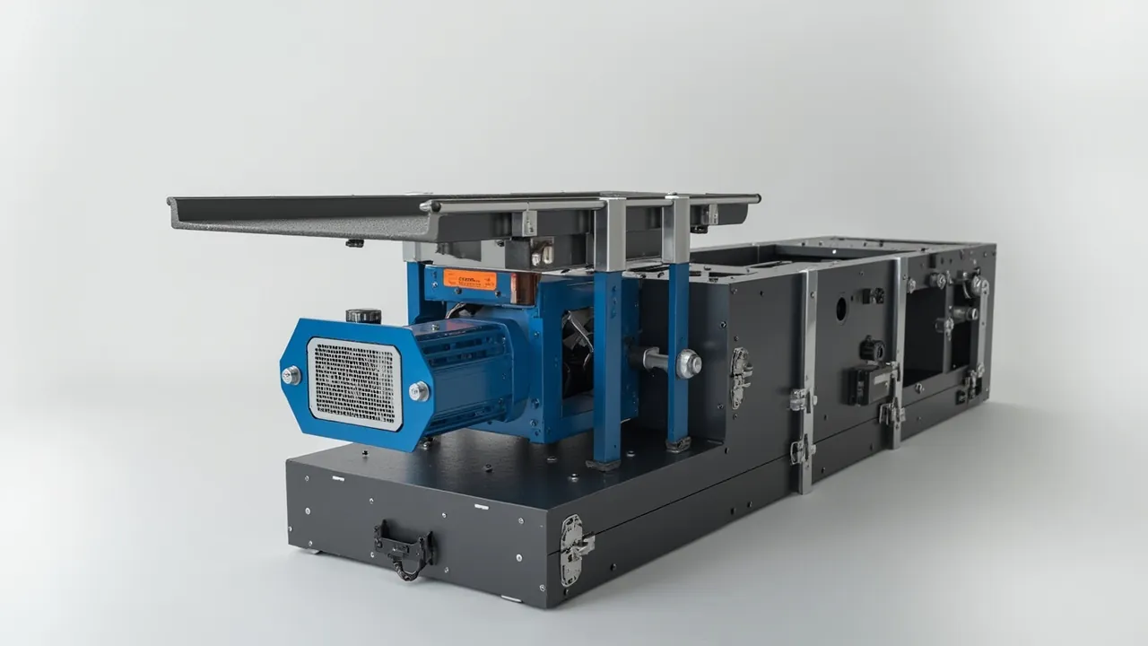
A significant share of vibrating screen downtime is not caused by worn screen media but by exciters and deck frames that were already out of tolerance before installation. An exciter is a high-speed rotating eccentric mass running on bearings with clearances measured in microns, so excessive shock in transit can shift eccentric phase or bearing preload. A deck frame or cross beam is a long slender member, often spanning 3 to 6 m, and any improper stacking load leaves a bend that is invisible to the eye yet shows up on the assembled machine as uneven amplitude and resonance noise. The job of a vibrating screen parts case is therefore not to fit the components in, but to deliver them with dynamic balance and straightness intact.
The two component families demand opposite packaging directions: exciters fear shock, deck frames fear distortion. Treating them alike produces a case that is neither sufficiently isolated nor sufficiently stiff against bending. This article works along three lines, exciters, deck frames and tensioning hardware, and sets out restraint methods, isolation design, case stiffness requirements and acceptance references for screen manufacturers, mine spare parts buyers and packaging engineers.
Table of Contents
- Exciters and Deck Frames: Two Entirely Different Packaging Logics
- Exciter Construction and Its Transit Vulnerabilities
- Restraining Eccentric Blocks, Gears and Bearings
- Deck Frames and Cross Beams: Distortion Control for Slender Parts
- Managing Screen Tensioning Hardware as a Kit
- Isolation and Damping: Two Routes to Vibration Protection
- Case Stiffness and Resonance Avoidance
- Protecting Balanced Assemblies and Tolerance Surfaces
- Moisture, Dust and Electrical Component Handling
- Handling Interfaces and Site Installation Fit
- Test Verification: Test Set and Acceptance Criteria
- Custom Delivery and Batch Consistency Control
- Frequently Asked Questions
- Conclusion and Further Reading
Exciters and Deck Frames: Two Entirely Different Packaging Logics
Putting an exciter and a deck frame in the same case is the most common cost-saving shortcut in vibrating screen spare parts packaging, and it is also the one most likely to cause problems. The reason is that the two component families tolerate restraint in opposite ways: an exciter needs compliant restraint to isolate high-frequency shock, while a deck frame needs rigid restraint to resist bending.
An exciter body typically weighs 200 to 1500 kg and contains eccentric blocks, a gear pair, bearings and a lubricant cavity. It is very stiff externally, but its internal fits are precise. Once external shock acceleration exceeds a certain level, eccentric blocks can shift angularly on their shafts, gears can be knocked slightly out of mesh, and bearing races can be brinelled. Damage of this kind is very hard to see by eye at site, yet it appears in service as abnormal vibration, elevated temperature or unusual noise.
Deck frames and cross beams carry a different class of load. A 4 m cross beam already deflects under its own weight, and if other spares are stacked on top in transit, the deflection superimposes and can exceed the elastic limit, so the beam does not fully recover after unloading. On assembly this appears as an uneven screen surface, gaskets that will not compress properly, and a non-uniform amplitude distribution.
| Component | Critical precision metric | Main failure mode | Packaging strategy |
|---|---|---|---|
| --- | --- | --- | --- |
| Exciter body | Bearing clearance, eccentric phase | Shock damage, misalignment | Compliant isolation plus located restraint |
| Eccentric block assembly | Phase angle, tightening torque | Angular shift, loosening | Separately secured plus locked |
| Gear pair and bearings | Mesh clearance, preload | Brinelling, micro misalignment | Low acceleration design |
| Deck frame | Straightness, flatness | Bending, twisting | Rigid support, no stacking load |
| Cross beam | Straightness | Bending | Support at ends plus centre restraint |
| Tensioning hardware | Dimensional fit | Deformation, loss | Compartments plus kit control |
The table points to one conclusion. An exciter should be allowed to move a little, but only a little. A deck frame must not move at all. One case rarely achieves both, so the first recommendation here is to ship them in separate cases, or at minimum to create a genuine physical partition inside a shared case.
Exciter Construction and Its Transit Vulnerabilities
Exciters divide into gear-synchronised box types, single-shaft eccentric block types and twin-shaft types, and the transit vulnerabilities differ across the three.
Gear-synchronised exciters contain a gear pair coupling two eccentric shafts, with mesh clearance typically in the tens of microns. If a metal-to-metal impact occurs in transit, the shock wave travels along the shaft system into the gear mesh and leaves marks on the tooth flanks. Packaging for this type must eliminate rigid contact entirely, with an elastic material transition at every support face.
Single-shaft eccentric block exciters are structurally simpler, and the main risks are holding eccentric block position and preventing fastener loosening. Eccentric blocks are normally fixed to the shaft by a key or a locking assembly, and transit vibration can decay the preload.
Twin-shaft and multi-shaft types add a further requirement to preserve relative shaft position, so the case must prevent any torsional movement of the exciter as a whole.
Lubricant cavities and oil seals are another overlooked point. Exciters usually ship with oil or grease already charged, and elevated temperatures in transit raise internal pressure, which can force leakage past an inadequate seal. For summer long-haul transport, manage the temperature inside the case and avoid prolonged direct sun. Because oil level differs between vertical and horizontal attitudes, the packing attitude should match the transport attitude so that oil does not flood areas that should stay dry.
Surface protection requirements: mating faces, mounting flange faces and seal lips are critical surfaces. They need face protection and must not come into contact with any foreign object. Flange flatness directly determines seating and sealing after installation, and a scratch in transit means re-lapping on site.
Restraining Eccentric Blocks, Gears and Bearings
The core of restraint design is to treat the component and its internals as two separate layers. External restraint prevents gross movement; internal restraint, completed by the manufacturer before shipment, prevents relative movement of parts. Packaging mainly controls the former.
Restrain in at least three horizontal directions. Horizontal movement of the exciter inside the case should stay within 5 mm. Achieve this with a recessed base plus side stops, not with straps alone. Between stops and exciter body, provide a 10 to 15 mm elastic transition layer so contact is never rigid.
Apply vertical compression. Set the top compression layer at 20 to 30 percent of material thickness so that closure produces continuous clamping force. Too little clamping allows vertical bounce; too much transmits the internal load back into the exciter housing.
Prevent rotation. Eccentric shafts usually protrude, and they must not carry bending moment in transit. Where a shaft end extends significantly, fit a dedicated support bracket that transfers the shaft end weight into the case structure instead of leaving the shaft unsupported.
Never load bearing zones directly. The bearing housing area of an exciter is a thin-wall transition and should not be a primary support point. Place supports on thickened body sections or dedicated support feet.
Locking of fasteners must be confirmed before packing. Eccentric block bolts should be torqued and locked to the in-house specification using thread locking compound or locking washers. The packaging step only needs to prevent further loosening from external vibration, which can be verified on arrival by paint marks on critical fasteners.
Deck Frames and Cross Beams: Distortion Control for Slender Parts
A deck frame is the skeleton of a vibrating screen, usually fabricated from side plates, cross beams, ribs and connection flanges. The span can reach 3 to 6 m while wall thickness is often only 8 to 16 mm. Such a long-span thin-wall structure already deflects noticeably under its own weight, and stacking load becomes the last straw for straightness.
Follow the two-ends-plus-centre support rule. Three-point support is the basic practice for slender members: one support at about 1/8 of the span from each end and one at mid-span keeps maximum deflection within a reasonable range. For longer members, add a support every 1.5 m.
Never stack load at mid-span. If other spares must share the case, their weight should pass through the case structure rather than onto the deck frame. The practical method is to fit support columns taller than the top of the deck frame so that upper cargo lands on the columns.
Protect side plate flatness. Side plates normally carry the bearing housings and exciters, so their flatness and hole position directly determine machine assembly quality. Store side plates vertically or on edge rather than flat, where their own weight can bow them.
Control cross beam torsion. Beam sections are usually tubular or channel shaped, strong in bending but weak in torsion. Fit restraints that prevent rotation about the longitudinal axis, normally a profile channel matching the section.
Ribs and welds are stress raisers and should not be direct support points. Supports belong on the beam body or on process bosses.
Managing Screen Tensioning Hardware as a Kit
Screen tensioning hardware comprises tension plates, wedges, tension bolts, rubber cushion strips and clamping bars. These are matched sets with the deck frame, and a single missing item can block machine assembly.
Pack by screen deck. Vibrating screens frequently have one, two or three decks, each with different tensioning hardware. Compartmentalise by deck, secure the contents with ties and mark the deck number, so hardware cannot be mixed up on site.
Protect tension plate edges. Tension plates are usually folded thin sheet, and the folded edge can crack at the weld under load. Fit soft corner protectors at the folds and keep them from direct contact with other metal parts.
Store rubber cushion strips without compression. Rubber strips lose elasticity under compression, which degrades sealing and vibration damping. Coil them or lay them flat in a dedicated compartment with nothing stacked above, and avoid heat since prolonged exposure above 60 degrees Celsius accelerates ageing.
Kit list plus installation drawing. For multi-deck machines, include a deck-by-deck installation sketch identifying the hardware kit number for each deck. This drawing-plus-parts approach substantially reduces mis-assembly, following the same logic as the segment-by-segment kits described in the conveyor roller component case reference.
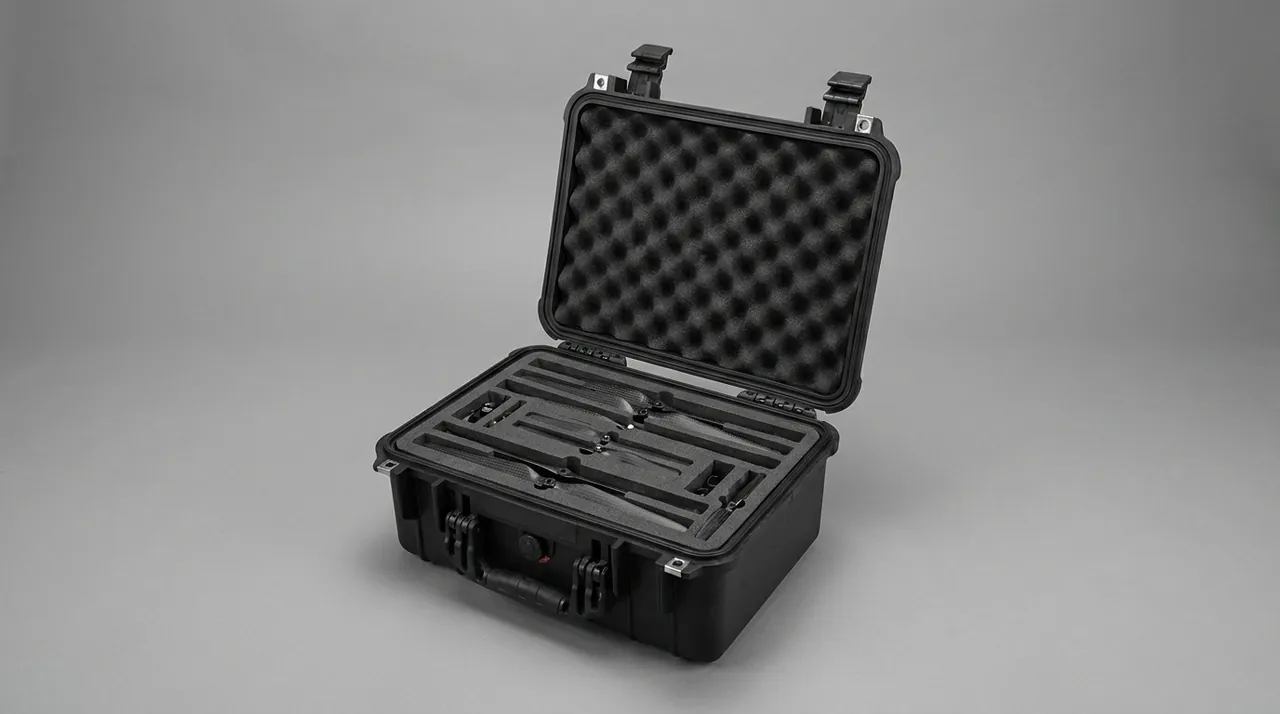
Isolation and Damping: Two Routes to Vibration Protection
There are two technical routes to vibration protection, isolation and damping. The physics differs and so do the applications, and mixing them up produces a system that is neither soft enough nor stable enough.
Isolation works by cutting the transmission path. Fit a low-stiffness elastic element between component and case so the system natural frequency sits well below the input excitation frequency, which reduces transmissibility. As a practical target, keep the support system natural frequency below 5 to 10 Hz, which gives useful attenuation across the main road transport band of 5 to 20 Hz. Isolation elements can be low-density foam, rubber isolation pads or spring structures. Springs are efficient but need calculation, while foam is simple but performance depends entirely on compression design.
Damping works by dissipating vibratory energy. Introducing high-damping materials or layered composite structures converts vibration energy into heat. Damping is especially effective at suppressing response in the resonance region, where isolation alone would amplify amplitude.
The practical combination uses isolation elements for the main attenuation and high-damping materials to handle resonance peaks. In practice, lay isolation pads at the base, add a damping layer between the component and the side stops, and compress the top with a compressible material.
The governing parameter is acceleration, not displacement. For precision components such as exciters, the acceptance metric is the peak acceleration transmitted to the component, not whether the case survived intact. Measure it with accelerometers fitted to the actual component, or derive an equivalent design from existing test data for similar products. Shock isolation design thinking is covered in the cushion liner and shock isolation reference.
Case Stiffness and Resonance Avoidance
Vibration protection has an easily forgotten precondition: the case itself must be stiff enough, otherwise its own low-frequency modes couple with transport excitation and amplify the problem.
Keep the first bending mode away from the excitation band. For a long case, as used for deck frames, the first bending frequency can land between 10 and 30 Hz, which overlaps the high-energy band of road transport. Countermeasures include increasing section height, adding stiffening ribs, bracing inside the case, or moving to a steel-timber composite structure.
Avoid coupling between case and component. If the component also has a low-frequency mode, close frequencies amplify each other. Design the component support system natural frequency to sit below the case mode frequency, with a factor of two or more as a working margin.
Panel diaphragm effect. Large thin panels vibrate as diaphragms under acoustic and aerodynamic excitation, creating secondary internal excitation. Suppress this with greater panel thickness or stiffening ribs.
Connection loosening control. Long-term vibration progressively loosens bolted connections. Use locking washers or thread locking compound on critical case connections and inspect tightness after a defined number of use cycles.
For overall transport test methods and intensity level selection, see the ISTA transport testing procedure reference.
Protecting Balanced Assemblies and Tolerance Surfaces
Exciters are dynamically balanced before shipment, with balance quality expressed as residual unbalance, commonly in gram-millimetres per kilogram. Transit does not change mass distribution, but it can destroy the balanced state in two ways: angular shift of eccentric blocks, and bending of the shaft system.
Preventing angular shift requires that eccentric blocks see no torque about the shaft in transit. Beyond fastener locking, add angular stops in the case so the block cannot rotate when it contacts the internal restraint.
Preventing shaft bending requires that any protruding shaft end be supported. The bracket should conform to the shaft journal outside diameter with a soft pad at the contact face, and the bracket position should be adjustable to accommodate machining tolerance.
The tolerance surface protection list should include at least the mounting flange face, bearing housing fits, seal lips, gear mesh surfaces where exposed, and shaft journals and coupling fits. Film these before packing, and make sure the film contains no plasticiser that can migrate.
Quantified arrival inspection criteria should be written into the contract: eccentric phase marks matching the factory record, mounting flange free of scratches, shaft run-out within tolerance, and bearings that rotate freely without binding or noise. Quantified criteria are what make acceptance objective.
Moisture, Dust and Electrical Component Handling
Vibrating screen spares often include vibration motors, sensors, terminal boxes and control elements, whose packaging requirements differ from mechanical parts.
Vibration motors need both moisture and shock protection. Motor windings are moisture sensitive, and prolonged high humidity reduces insulation resistance. The packaging answer is barrier film plus desiccant, with a humidity indicator card inside the case. Motors are also shock sensitive and need elastic support.
Acceleration and displacement sensors are precision devices with a specified allowable shock level, commonly a few hundred g for short duration. These must be packed separately with multi-layer cushioning and marked as precision instruments with a do-not-drop symbol on the outer case.
Terminal boxes and cables need protection from compression and moisture. Cable coiling radius should be at least three times the minimum bend radius so conductors are not damaged internally.
Dust protection matters greatly in mineral processing and cement settings. Fine powder entering a terminal cavity reduces insulation and causes poor contact. Use a sealed structure, or fit dust caps at openings.
Sealing and pressure differential: for spares held in long-term storage, a sealed case develops internal pressure differential from temperature swings. Design practice is covered in pressure equalisation valve for protective cases, while case sealing and latch strength matching is discussed in toolbox hinge, latch and seal structure.
Handling Interfaces and Site Installation Fit
Site conditions for vibrating screen spares vary widely, from a fully equipped assembly plant to a mine site with a single wheel loader. Handling interfaces should be designed for the worst case.
Align lifting points with the component centre of gravity. Exciters usually have lifting lugs on top, and the case should provide a lifting path so the rigging can connect directly to the component lugs without unpacking first. This has a large effect on installation efficiency.
Fork pocket centres should match common forklift fork spacing, typically adjustable between 500 and 1200 mm. For long deck frame cases, put fork pockets near the two ends so a centre lift does not over-deflect the frame.
Design for roll-out after opening. For a heavy exciter, use a structure where the lid opens and the pallet rolls out, so the site can pull the pallet out with a forklift rather than levering the component inside the case.
Temporary storage state after unpacking also matters. If installation cannot start immediately, the component needs temporary storage. The liner pallet can be designed to double as a temporary stand, or a set of support feet can travel in the case so the component holds the correct attitude after unpacking.
Marking systems should cover centre of gravity, lifting points, opening sequence, temporary support positions and no-stack zones. For deck frame cases, mark the top clearly as no stacking.
Test Verification: Test Set and Acceptance Criteria
Test verification for vibrating screen spares operates at two levels: the packaging item test and the component function check.
Packaging item tests follow the GB/T 4857 series, typically covering stacking under GB/T 4857.3 or .4, sinusoidal vibration under GB/T 4857.7, random vibration under GB/T 4857.10 where applicable, and drop or incline impact under GB/T 4857.5 and .11. Export scenarios can add an ISTA 3E unitised load test or an ASTM D4169 distribution cycle.
Key vibration test parameters are frequency range, acceleration spectral density and duration. Road transport is usually run as a 5 to 200 Hz sweep or against a random vibration spectrum, with duration scaled to the equivalent transport distance.
Key shock test parameters are peak acceleration and pulse duration, commonly a half-sine pulse of 6 to 11 ms. For components such as exciters, acceptance should be based on the response measured on the actual component.
Acceptance has three tiers: no structural failure of the packaging, no displacement or loosening or cosmetic damage on the component, and critical precision metrics such as eccentric phase, straightness, flange flatness and rotational freedom within limits. The third tier matters most and is the one most often omitted.
Note that MIL-STD-810H is an environmental test method standard, cited as a basis for environmental testing where required. It is not a product certification.
Custom Delivery and Batch Consistency Control
Custom packaging for vibrating screen spares must handle both model variety and batch consistency. Screen models are numerous, and within one series the exciter and deck frame dimensions can differ widely, while the packaging logic remains reusable.
Modular design is the key to consistency. Split the case into a universal shell and a dedicated liner. Standardise the shell into a few load ratings and customise the liner per component model. This covers many models while reducing tooling cost per model.
Tolerance control concentrates in three places: liner pocket position tolerance, which sets restraint accuracy; support point height tolerance, which determines whether multi-point support is actually achieved; and lid closure gap, which determines whether clamping force is effective. Include all three in first-article inspection and batch sampling.
Delivery milestones run in this order: provide component drawings and samples, confirm centre of gravity and support points, receive case and liner proposal, prototype validation, test confirmation, pilot batch, then volume delivery with inspection records retained per batch.
Three common mistakes: underestimating the case stiffness needed for a long deck frame span, treating an exciter as ordinary heavy cargo and omitting isolation, and forgetting to leave a site lifting path. All three are caught by prototype validation.
JUNZHJIA supplies custom isolation liners, modular heavy-duty case structures and accompanying installation marking systems for vibrating screen and screening equipment manufacturing and maintenance, supporting custom and joint development projects with worldwide delivery. Where the screen is already covered by a proven packaging specification, equivalent replacement plus test verification can be carried out against it.
Frequently Asked Questions
Q: Can an exciter and a deck frame share one case?
A: Technically yes, but it requires a genuine physical partition and should not be the default. The partition requirement is that the exciter zone uses compliant isolation support with independent restraint, the deck frame zone uses rigid support with no load at mid-span, a rigid divider separates the two, and the base load paths run separately into the case main beams. The problem is that space and weight budgets rarely allow such an extravagant partition. The more realistic compromise is separate cases delivered in the same batch, and the added case cost is usually lower than dealing with a misaligned exciter or a bent cross beam on site. If a customer insists on a shared case, run a full-case vibration test at prototype stage with accelerometers on both the exciter and the deck frame, and let the measured response decide whether the arrangement is acceptable.
Q: How do I judge whether vibration protection is adequate?
A: Look at two levels. The first is the packaging level: after sinusoidal vibration per GB/T 4857.7 or random vibration per GB/T 4857.10, the case shows no structural failure and components show no displacement. The second is the component level: fit accelerometers to the actual component, measure the peak acceleration transmitted to it, and compare against the allowable value given by the manufacturer. This second level is often skipped but is essential for exciters, because the case can survive intact while the component is already damaged. Without measurement, derive an equivalent assessment from existing test data for similar components and similar packaging, and state that basis in the contract. Test duration should be scaled to the equivalent transport distance rather than substituting a few minutes of short-term testing for validation of a long journey. Where the customer has no accelerometer capability, request the allowable shock level from the component manufacturer and design the liner against that figure.
Q: How should support points be arranged for deck frames?
A: The basic approach is three-point support: two ends plus the centre. Place the end supports about 1/8 of the span from each end and one at mid-span, which keeps maximum deflection small. Above a 4 m span, add a support every 1.5 m, so a 4 m span gets four points and a 6 m span gets five. Supports must sit on the beam body or a process boss, never on a rib or a weld, because those are stress raisers that can initiate cracks under pressure. Place a rubber or EVA pad 8 to 15 mm thick between support and component, which both cushions and distributes pressure. Where site conditions allow, standing the frame on edge preserves straightness better than laying it flat, but this requires a continuous bottom channel and an angle of 75 to 85 degrees. Finally, check that the support layout does not create a hard point at a machining boss, where concentrated pressure can distort the bore.
Q: Can the eccentric phase shift in transit?
A: It can if the packaging is poorly designed. Phase retention depends on fastener preload and the locating feature on the shaft, whether a key or a locking assembly. Sustained transit vibration decays bolt preload, and once it has decayed enough, a shock event shifts the eccentric block angularly. Prevention has three parts: torque the fasteners to specification at the factory with thread locking compound or locking washers; fit angular stops in the packaging so the block cannot rotate about the shaft; and control the acceleration transmitted to the component through isolation design. On arrival, check the phase marks against the factory record and re-verify tightening torque. If the phase has changed, rebalance the assembly; do not install it as is. Keep the arrival report with the machine record, because a phase shift discovered later in service cannot be attributed to transit once the evidence has been filed away.
Q: What should be considered for sea freight of vibrating screen spares?
A: Sea freight brings long duration, large temperature and humidity swings, and continuous alternating loads from vessel motion, so three areas need reinforcement. First, moisture: increase desiccant quantity, fit a humidity indicator card, and use aluminium-laminate barrier film where necessary. Second, lashing: estimate strength at 0.4 g longitudinally and 0.5 g laterally, run crossed lashings and verify lashing point strength. Third, stacking: keep long deck frame cases to two high at most, and ensure no upper load reaches mid-span, normally by fitting support columns taller than the component. Wooden packaging must meet ISPM 15, and oil-bearing components require assessment against the applicable transport provisions. On arrival, check the humidity indicator card and tilt indicator immediately; if triggered, open and inspect at once and document the findings to support liability allocation. Finally, confirm that lashing hardware is not reused after a voyage in which it has been loaded close to its rated capacity.
Q: How do I choose liner material that isolates without losing restraint?
A: The key is to assign isolation and restraint to different zones rather than asking one material to do both. Use low-stiffness material for isolation, such as low-density PE foam at 25 to 35 kg per cubic metre or a rubber isolation pad, allowing larger compression travel to absorb energy. Use high-stiffness material for restraint, such as high-density EVA at 60 to 80 kg per cubic metre or rigid polyurethane, machined into pockets matching the component profile to hold movement within 5 mm. For components such as exciters, also fit a separate support bracket at the protruding shaft end with a soft pad at the contact face to avoid scoring the journal. If one material must serve both roles, split the zones within a single EVA block using different thicknesses and cut-outs for a soft-to-hard transition, but this approach costs more to design and validate and suits larger batch projects.
Q: Can the case itself resonate with transport vibration?
A: It can, and this is especially common with long cases. The first bending mode of a long deck frame case can fall between 10 and 30 Hz, overlapping the high-energy band of road transport. Once coupled, case deflection amplifies the internal component response and defeats even a good liner. There are four countermeasures: increase section height to raise bending stiffness; add stiffening ribs or diagonal bracing to the walls; move to a steel-timber composite structure; and design the component support natural frequency below the case mode frequency, ideally by a factor of two or more. For larger projects, run a modal analysis or a simple tap test to establish the measured first mode and confirm adequate separation from the transport excitation band before going into volume production. Where a full modal study is impractical, a simple tap test with an accelerometer taped to the case wall gives a usable first-mode estimate.
Q: What can packaging do if the spare cannot be installed immediately after unpacking?
A: It can serve as a temporary stand, and designing this in advance greatly improves the site experience. Three practical options: design the liner pallet to be independently load bearing, so the pallet and component can be lifted out together while holding the correct attitude; include a set of removable support feet so the component can be propped after unpacking rather than set on the ground; and design the lid to be usable inverted as a temporary raised platform. Also include a temporary storage instruction sheet covering maximum storage duration, allowable environmental conditions and inspection points. For oil-bearing components such as exciters, the storage attitude should match the transport attitude so oil distribution does not become abnormal, while rubber and electrical parts should be kept out of direct sunlight and high temperature. State in the storage instruction whether the liner pallet is rated for the full component weight or only for handling support, so the site does not overload it.
Conclusion and Further Reading
The difficulty in vibrating screen spare parts packaging is not moving a two tonne casting into a box, but satisfying two opposing technical requirements at once. The exciter must be compliantly isolated to keep acceleration low; the deck frame must be rigidly restrained to keep straightness stable. Separate the two and the design stays sound.
Proceed in four steps: decompose the packaging logic by component type, define isolation elements and support point layout, verify transmitted acceleration through full-case vibration testing, and write the quantified acceptance criteria into the contract. For deck frames spanning more than 4 m and for high-precision exciters, design dedicated packaging rather than reusing a general heavy-duty case.
JUNZHJIA serves vibrating screen and screening equipment manufacturers and maintenance teams with machine-specific isolation liners, modular heavy-duty case structures and accompanying installation marking systems, supporting OEM and ODM programmes and global supply, with material and test documentation available by contract.
Further Reading