

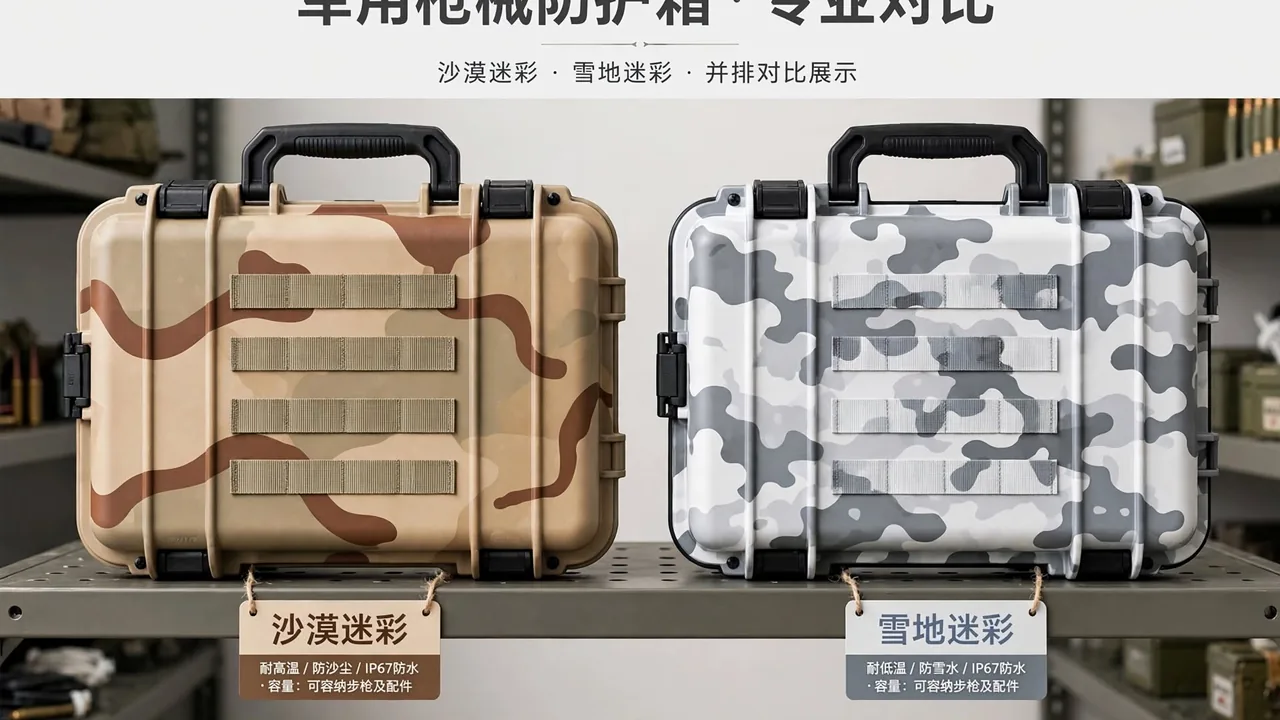
A communication equipment case is an easily underestimated product. Many buyers treat it as nothing more than a sturdier instrument box, a shell with foam inside where radios, handsets, and cables can be dropped. Anyone who has actually run a radio frequency program knows better. A Communication Equipment Case has to serve two physical requirements that pull against each other. It must let the electromagnetic energy radiated by an antenna pass through the enclosure, it must keep outside interference away from the equipment, and it must keep water and dust outside as well. Those three jobs correspond to RF transparency, electromagnetic interference shielding, and sealing. Miss any one of them and the specifications printed on the case become numbers on paper. This article covers container-side design tradeoffs only, and stays away from internal circuitry and communication protocols.
From a packaging engineering standpoint, the product can be defined as a protective container with a selective electromagnetic interface. Selective is the operative word. The shell treats electromagnetic energy differently depending on frequency: it should be as transparent as possible at the equipment's own operating band, and as opaque as possible to out-of-band interference. No single material delivers that behavior. It requires layered structure, with a load-bearing layer for mechanical strength and sealing, a conductive layer for shielding and equipotential bonding, a dielectric window for transmission, and a liner layer for positioning and static dissipation. Before starting such a container, a sensible manufacturer confirms three boundary conditions with the user: the operating band, the longest antenna that will travel inside the case, and whether the case will remain outdoors for extended periods. Those three answers frame every structural decision that follows.
Why a General-Purpose Protective Case Cannot Simply Be Adapted
A general protective case exists to separate its contents from the environment, so its default instinct is airtight and conductive wherever possible. Applied to radio equipment, that instinct fails immediately. A fully conductive closed shell, whether solid metal or entirely coated, forms a cavity that strongly attenuates signals whenever the equipment must remain on receive with its antenna inside. The radio ends up in a shielded cabinet. The opposite extreme fails just as badly: an entirely plastic case with no conductive treatment lets electrostatic discharge and strong external fields couple straight into the electronics. Neither extreme is correct, because the real question is not whether to shield but where to shield and where to stay transparent.
A second reason general cases do not transfer is the electromagnetic continuity of the opening interface. A general case only worries about sealing where lid meets body, and small gaps are tolerable. In a radio scenario, an untreated seam behaves like a slot antenna, and leakage rises sharply once the seam length approaches a fraction of the operating wavelength. The closure on a communication case therefore has to serve sealing and electromagnetic continuity at once, which usually means a gasket and a conductive pad sharing one groove or occupying two parallel grooves. A third reason is accessory management. Antennas, feed cables, chargers, and spare batteries have wildly different shapes, and a generic foam cavity cannot restrain a slim rod and a dense battery block with equal success. Dedicated retention features are required. General requirements for comparable enclosures appear in the communication electronics protective case overview.
RF-Transparent Windows: Dielectric Loss, Thickness, and Band
The RF-transparent window is the feature that distinguishes a communication case from every other protective enclosure. Its job is to create a region of the shell that is low-loss at a chosen band, so an antenna inside can still transmit and receive effectively. The usual implementation embeds a low-loss dielectric panel into the wall, typically an engineering plastic sheet, a glass-reinforced laminate, or a compound formulated for the band. The key parameters are permittivity and loss tangent. Lower permittivity reduces phase distortion as the wave crosses the panel, and a smaller loss tangent reduces attenuation. Thickness is a tradeoff between stiffness and electrical performance. More thickness raises rigidity but can increase loss and shift the window's effective electrical length.
Geometry matters as much as material. The window should face the antenna's primary radiation direction and avoid metal hardware, hinges, and latches. Where the antenna is removable, the window must align with the intended mount position, or users will aim the antenna at solid shell. In size, the clear aperture should exceed the antenna's projected footprint with a transition margin around it, because the window edge is where the field changes abruptly and a poor edge treatment creates a local hot spot. Multiband equipment complicates the picture further, since low and high bands respond differently to the same formulation. Where one panel cannot serve all bands, separate windows with different materials, or acceptance of some attenuation in a secondary band, may be the practical answer. Layered shielding and transmission strategies are described in the EMI shielded case reference.
Shielding Pads, Windows, and Seam Treatment
Shielding addresses the other half of the problem: keeping interference out. Three forms dominate practice. Conductive fabric gaskets compress well at moderate cost and suit long seams around a lid. Conductive silicone combines sealing with conductivity in one part, which suits interfaces needing both water resistance and shielding, though its filler can raise contact resistance after repeated compression. Metal finger stock delivers high effectiveness and long life but demands tight control of compression and mounting flatness, and a small misalignment costs contact. The selection sequence is to fix the shielding target and compression conditions first, then trade cost against service life, rather than starting from unit price.
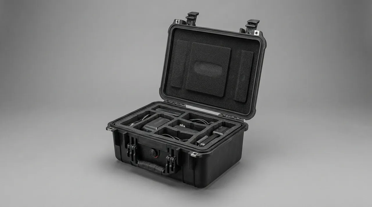
Seam treatment is where shielding design is genuinely difficult. Even with the best gasket available, a single uncompressed segment or one run interrupted by paint film lets the longest gap govern the whole perimeter. Three process controls matter. The gasket groove must be machined precisely enough to avoid locally insufficient compression. The shell surface in the contact zone must be conductive, which means masking or post-processing is required wherever an insulating topcoat is applied. Fastener spacing must be close enough to keep compression even within the lid stiffness available. Where a viewing window or display is needed, a conductive mesh or coated glass replaces the ordinary transparent part so the aperture joins the shielding system. If the equipment itself has demanding electromagnetic requirements, container shielding is only one element, and it should be coordinated with the equipment's own filtering and grounding design.
Grounding and Equipotential Bonding: One Low-Impedance Path
A shield that is not effectively grounded has nowhere to send the energy it collects, so its performance drops, and at some frequencies it can even amplify interference through resonance. Three rules govern grounding in a communication case: low impedance, a single preferred path, and dependable joints. Low impedance means short, wide connections with generous contact area, not a thin wire running to a distant point. A single preferred path means avoiding multiple ground points that form a loop, since a loop couples external magnetic fields into the system. Dependable joints mean the grounding stud and its bond to the shell survive corrosion treatment and repeated assembly.
In practice, grounding divides into three parts. Inside the case, a stud or busbar connects the equipment chassis to the conductive liner. Structurally, the lid, body, and hardware are bonded into one potential through conductive gaskets or jumper straps. Externally, a grounding interface lets a user tie the case to earth at a fixed site. The second part is the one most often overlooked. Although the lid and body are bonded through the seam gasket, a hinge on one side without an additional jumper forces the current along a long single-point path. A practical fix is a removable braided jumper diagonally opposite the hinge, with torque and replacement interval stated in the assembly document. Grounding looks minor on a drawing, yet it decides whether measured shielding performance survives real use.
Shell Materials and Metallization Routes
Three technical routes dominate. The first is a plastic shell with a conductive coating, commonly a conductive paint or electroless plating on interior surfaces. It offers low weight, design freedom, and controllable cost; the difficulty lies in coating uniformity at corners and deep cavities, and in wear resistance where parts rub during repeated assembly. The second is a metal shell, where aluminum provides inherent conductivity and stable shielding at the price of weight, cost, and galvanic corrosion management where metal meets the RF window. The third is a composite wall, layering structural, conductive, and dielectric materials. It is the most flexible and also the most complex, suited to programs with simultaneous weight and performance targets.
Three variables drive the choice: operating band, weight ceiling, and corrosion severity. At high frequencies, surface quality and seam continuity matter more than bulk material. Where weight is critical, plastic with coating has a clear advantage. For long outdoor or maritime service, galvanic corrosion at metal-to-metal contacts must be handled in advance, for example with insulating washers between aluminum and stainless steel or with compatible fasteners. Whatever the route, the drawing should state which surfaces must be conductive and which must stay insulating, and that information has to reach coating, assembly, and inspection. Without it, a single layer of clear lacquer over a critical contact zone can ruin shielding for the whole perimeter.
Liners and Retention: Antennas, Cables, Batteries, Handsets
Accessory shapes vary so widely that liner design has to treat each class separately. An antenna is a slim, fragile rod that fears lateral impact and bending, so it belongs in a dedicated channel or circular seat, lying vertically or horizontally with an elastic clip limiting axial movement. It should never share a layer with heavy items, because transport inertia will press directly onto it. A feed cable is flexible, and what must be controlled is its minimum bend radius; a winding post smaller than that radius gradually fatigues the inner conductor and shield until they break.
Batteries deserve the most attention because they carry the highest weight per unit volume. A battery bay belongs low in the case or near primary structure, with its own clamping mechanism, so a drop does not transmit shock into lighter neighbors. Handsets and chargers, being medium weight, suit molded foam positioning under a flexible pressure plate that balances location accuracy against access convenience. When the liner also performs static dissipation, material options narrow to volume-conductive or surface-coated dissipative types whose resistance stays within the target band over time. General methods for vibration restraint and resonance avoidance are covered in the transport resonance analysis.
Meeting Sealing and Shielding in One Interface
The hardest structure in a communication case is the interface that must seal and shield simultaneously. Water resistance depends on gasket compression and shielding depends on pad compression, and both require sustained pressure, yet their optimal compression ranges do not fully overlap. A sealing gasket usually needs substantial compression for a dependable water line, while a conductive pad gains contact resistance and loses life when over-compressed. Stacking both in one groove forces the designer into a narrow window and demands extreme machining precision.
Separating the two functions in space is the more robust approach. One option is parallel grooves: an outer groove for the sealing gasket and an inner groove for the conductive pad, with matching compression ridges on the lid, so each material works in its own optimal range without interfering. The other option is functional consolidation using conductive silicone that both seals and conducts, which simplifies structure but concentrates risk in a single material. The parallel-groove design costs a little height and machining but is worth it where shielding must hold up over years. Compression set also deserves attention, since insufficient recovery after many open-close cycles lowers contact pressure locally. The pad replacement interval and compression inspection should therefore appear in the maintenance manual.
Thermal Management Inside a Sealed Case
Radio equipment generates heat while working, and a communication case is usually sealed tightly enough that heat can only leave through the shell. That makes thermal management part of container design. The baseline path is conduction: a thermal pad or metal bracket links the main heat-generating surface to the shell, which then releases heat to the environment. Continuity of that path is critical, because an air gap in the middle raises thermal resistance sharply and internal temperature climbs.
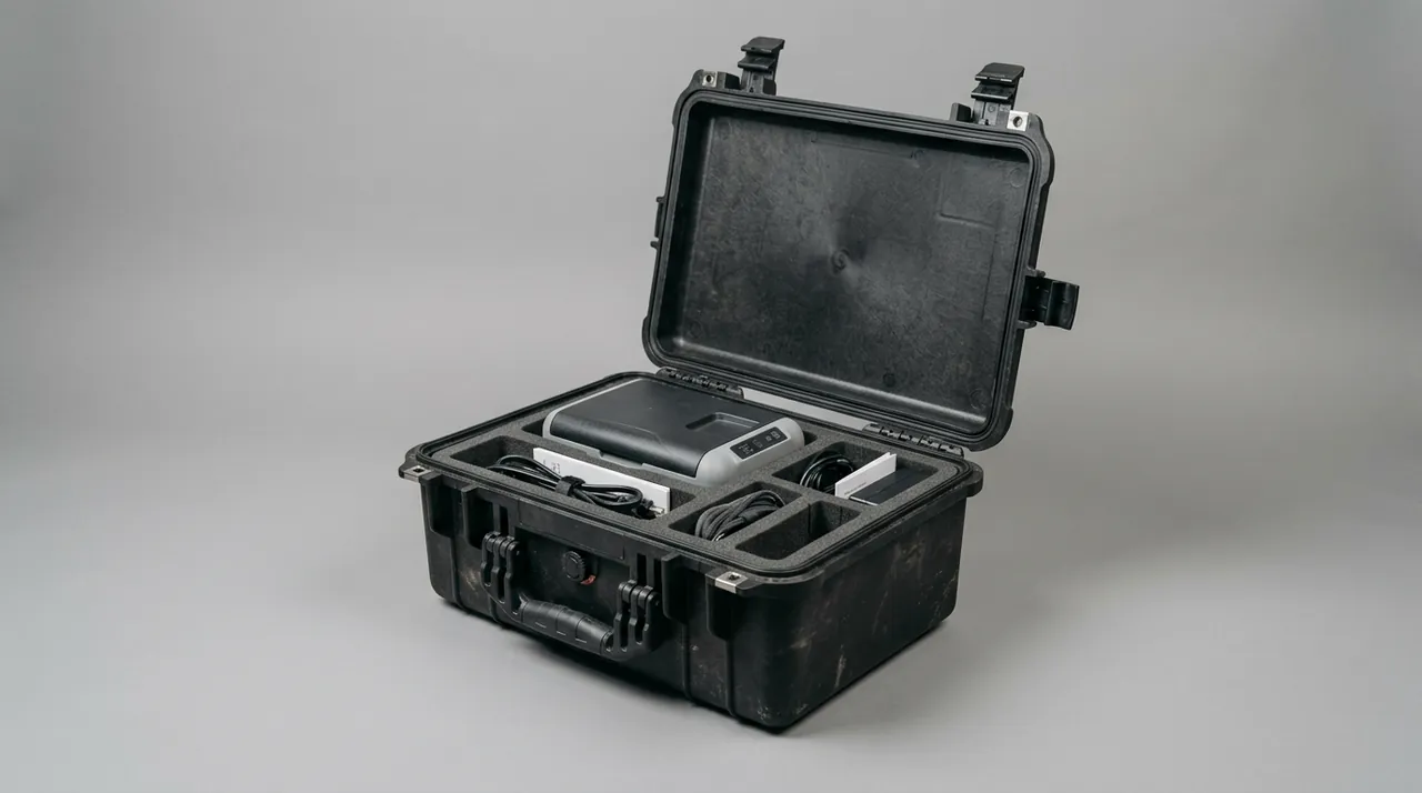
Where more cooling is needed, convection or forced air becomes attractive, but that conflicts with sealing and requires compromise. A common compromise exchanges heat without exchanging air: a metal heat exchanger block or heat pipe embedded in the wall moves heat out without an open vent. Another approach uses a filtered labyrinth vent that allows air movement while making it difficult for droplets and dust to enter. A third strategy reduces internal heat load by keeping equipment in low-power standby inside the case and scheduling high-power operation for when the case is open. Whichever route is chosen, temperature sensors should be placed at critical interior points, and qualification testing should confirm that the internal temperature stays below the equipment limit under the worst ambient condition. This item is more easily forgotten than the RF specifications, yet it governs long-term reliability.
Carry and Transport: Backpack Interfaces, Stacking, Pressure
Communication cases move between fixed sites and field operations, so carry and transport interfaces must cover both. For carry, larger cases often accept a backpack frame, which requires defined mounting points and reinforced load-bearing zones on the back face, with the center of gravity kept close to the wearer's back, or long carries become punishing. Smaller cases rely on handles and shoulder straps, and handle capacity should be verified at several times the loaded weight, because dynamic loads during transport far exceed static weight.
For transport, cases travel in groups by vehicle and aircraft. When stacked, upper weight must pass through corners and posts while the lid carries no stacking load, so the sealing face does not deform and the compression of shielding pads does not drift. Air transport adds pressure change. A well-sealed case becomes harder to open as altitude rises, and glazing or display windows take additional stress. A pressure-equalization valve solves the opening problem, but the valve type must block water and dust while allowing air, and the valve itself is an electromagnetic leak, a deliberate path through the wall that needs dedicated treatment on a shielded case. General outdoor protection requirements are described in the outdoor case electronics protection guide.
Inspection and Acceptance: Verifying Shielding and Windows
Acceptance for a communication case adds two dimensions to the ordinary checklist. The first is sealing, still verified by spray or immersion testing to the stated IP level, unchanged from general practice. The second is shielding effectiveness, typically tested by reference to methods in the IEC 61000 series and reported as a measured value under the cited test method, which does not represent any military certification. The report should state whether the tested band covers the equipment's operating and interference bands, whether the case was in final configuration including gaskets, coating, and hardware, and whether testing occurred on the assembled product rather than on components. The third dimension is window verification, normally by comparison: the same equipment is measured open and closed, and the insertion loss introduced by the window is judged against the user's tolerance.
Acceptance documents should also cover items that are easily skipped: grounding resistance method and limit, sampling of pad contact resistance, cross-hatch adhesion testing of the coating, and re-testing of shielding effectiveness after a latch life cycle. The last item matters most, because shielding rarely degrades suddenly; it declines with accumulated open-close cycles as pads take a compression set, coatings wear, and fasteners loosen. Including post-cycle re-testing exposes that gradual failure before deployment. Where the equipment supports a critical link, a recurring re-test interval in the contract treats shielding as a maintained performance parameter rather than a one-time factory figure. Requirements for base-station and network tester cases appear in the communication test case guide.
Common Failure Modes: Oxidation, Open Grounds, Cracking
Failure modes map directly onto the multi-function structure. The first is rising contact resistance in conductive pads, caused by oxidation of the conductive filler or surface contamination, which lowers shielding. Countermeasures include corrosion-resistant plated fillers, avoiding bare-hand contact with conductive surfaces during assembly, and periodic contact resistance checks. The second is an open ground path, where a hinge jumper fatigues and breaks or a grounding stud loosens through corrosion, interrupting the current path. Making jumpers replaceable and specifying an inspection interval addresses it.
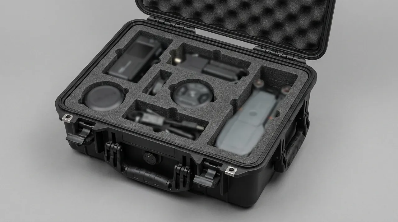
The third is cracking or delamination of the RF window, where the bond between panel and shell is stressed by thermal cycling and vibration until a crack or separation appears and transmission changes. Countermeasures include matching thermal expansion coefficients, using a compliant adhesive layer to absorb stress, and avoiding fastener-induced stress concentration around the aperture. The fourth is a cascade triggered by seal failure: water ingress corrodes electronics and also forms an electrolyte between pad and shell that accelerates galvanic corrosion. The fifth is hardware seizure, where latches and hinges corrode in salt fog until opening becomes difficult and a user pries the lid hard enough to distort it. Mapping these five modes to design inputs and the maintenance plan extends the useful service period substantially.
Procurement Pitfalls: Shielding Claims and Test Conditions
The most common procurement mistake is comparing shielding effectiveness as a standalone number. Shielding is a function of frequency, so a single figure without a stated band has almost no value. Test conditions also change results dramatically, and assembled-product figures cannot be compared with component-level ones, nor loaded with unloaded, nor final configuration with partial build. The practical requirement is a measured curve across a stated band, plus a description of the case configuration and the test method used.
The second pitfall is ignoring the cost of the window. Some proposals enlarge the RF aperture to produce attractive transmission numbers without weighing the resulting loss of mechanical strength, sealing, and shielding, leaving the window as the weakest region in the case. The third is comparing shells while ignoring accessories. Conductive pads, jumper straps, pressure valves, and grounding studs look like small parts, yet they determine whether performance holds over time, and with no spare parts channel the case life is set by its shortest-lived component. The fourth is treating the enclosure separately from the equipment design: container shielding and grounding are one element of the overall electromagnetic compatibility picture, so the supplier and the equipment team should agree in writing on grounding method, antenna position, and operating band. Writing these four points into the technical requirements is far more effective than repeated rework later. For military or export programs, confirm the compliance path under local regulations and export control requirements first, since container selection is subordinate to that constraint.
Closing Perspective: Transparent Where It Matters, Solid Everywhere Else
The difficulty of a communication equipment case is that it must be both a transparent wall and a solid shell. Transparency means letting electromagnetic energy through in the right place; solidity means keeping water, dust, impact, and interference out everywhere else, and the two pull against each other structurally. The answer is not a universal material but layered function: load bearing, sealing, shielding, and transmission each handled by their own layer, with precision and process controlling the interfaces between them. For buyers, sharing the operating band, antenna form, environment, and maintenance resources with the supplier lets the container be designed around real RF needs from the start, which is the only way to avoid a product that measures well and performs poorly in the field. Comparable military and electronics enclosure practices are discussed in the military electronics case guide and the 5G base-station case reference.
Frequently Asked Questions
Q: What is the core difference between a communication case and an ordinary instrument case? A: The core difference is that a communication case is a container with a selective electromagnetic interface, while an ordinary instrument case only separates its contents from the environment. Selectivity means the shell treats electromagnetic energy differently by frequency: it should be as transparent as possible at the equipment's own band so an internal antenna still works, and as opaque as possible to out-of-band interference and electrostatic discharge. No single material provides that behavior, so structure must be layered, with load bearing for strength and sealing, conduction for shielding and equipotential bonding, a dielectric window for transmission, and a liner for positioning and static dissipation. A general instrument case cannot simply be adapted because its default instinct is airtight and conductive everywhere, and a fully conductive closed cavity strongly attenuates an internal antenna. The reverse also fails, since an untreated plastic shell couples external fields and static directly into the electronics. Closure seams in a communication case must also serve sealing and electromagnetic continuity together, and accessory restraint is more demanding.
Q: How should the RF-transparent window material be selected, and is thinner always better? A: Dielectric loss comes first, mechanical performance second. Two parameters govern the electrical behavior: permittivity, where lower values reduce phase distortion as the wave crosses the panel, and loss tangent, where smaller values reduce attenuation. Common choices include engineering plastic sheet, glass-reinforced laminate, and compounds formulated for a specific band. Thinner is not automatically better, because thickness sits between two constraints. Too little thickness leaves the window flexible enough to distort or crack under pressure change and impact, and sealing may suffer as well. Excessive thickness increases loss and shifts the window's effective electrical length, changing transmission behavior. A sound method sets the maximum acceptable insertion loss from antenna aperture and band, then derives a thickness ceiling from it, while adding ribs or local thickening for rigidity. The edge transition zone deserves dedicated design as well, because that is where the field changes abruptly and poor treatment creates a local hot spot that can degrade performance or damage adjacent materials over time.
Q: Should shielding use conductive fabric, conductive silicone, or metal finger stock? A: The three suit different conditions, and selection should start with compression duty and service life before cost. Conductive fabric gaskets compress well at moderate cost and work along long lid seams in high-volume programs; their weaknesses are wear resistance and long-term recovery, so contact resistance needs monitoring after repeated cycles. Conductive silicone combines sealing and conduction in a single part, which suits interfaces requiring both water resistance and shielding and simplifies the shell, but its filler can raise contact resistance after repeated compression, and aging usually means replacing the entire ring. Metal finger stock offers high effectiveness and long life for demanding, frequently opened cases, but it is highly sensitive to compression and mounting flatness, so insufficient shell precision causes locally lost contact. Real programs often combine all three, using fabric along long runs and silicone or finger stock at corners and critical segments. Whichever is chosen, the acceptance document should define how contact resistance is sampled and what limit applies.
Q: Why must a communication case be grounded, and what happens when grounding is poor? A: A shield exists to collect interference and route it to ground, so an obstructed path leaves that energy with nowhere to go. The consequences appear at three levels. Shielding effectiveness falls, because contact resistance between pad and shell forms a series impedance that reflects and re-radiates energy at the seam. An antenna effect can develop, where a grounding path near a quarter wavelength of some frequency resonates and amplifies interference before radiating it into the case. Ground loops can form, with multiple ground points creating a closed circuit that couples external magnetic fields into the equipment as induced voltage. Grounding design therefore emphasizes low impedance, a single preferred path, and dependable joints. Hinge bonding deserves particular attention: if a lid connects to the body only through the seam gasket, current takes a long detour and the path becomes electrically narrow. Adding a replaceable braided jumper across the hinge is a common and effective remedy, and its torque and replacement interval belong in the assembly documentation.
Q: A communication case must both seal and shield. How are the gasket and pad coordinated? A: The key is to separate the two functions in space rather than stacking them in one compression groove. Sealing depends on gasket compression and shielding depends on pad compression, and while both need sustained pressure, their optimal ranges differ: a sealing gasket usually needs substantial compression for a dependable water line, whereas an over-compressed conductive pad gains contact resistance and loses life. Putting both in one groove leaves a narrow usable window and demands extreme machining precision, which is hard to hold in production, so some segment ends up under-compressed. The more robust approach uses parallel grooves, with an outer groove for the sealing gasket and an inner groove for the conductive pad, and matching compression ridges on the lid, letting each material work in its own optimal range. That design adds a little height and machining cost but is worth it where shielding must hold up for years. The alternative, a single material that both seals and conducts, simplifies structure but concentrates risk and needs life testing to prove stability.
Q: How is heat removed from inside a communication case? A: Because the shell is usually sealed tightly, heat leaves mainly by conduction through the walls. The baseline approach connects the main heat-generating surface to the shell through a thermal pad or metal bracket, shortening the resistance path; an intervening air gap raises thermal resistance sharply and internal temperature climbs. Where more cooling is required, convection or forced air becomes attractive but conflicts directly with sealing, so compromise is necessary. A common compromise exchanges heat without exchanging air by embedding a metal heat exchanger block or heat pipe in the wall, moving heat out without an open vent. Another uses a filtered labyrinth vent that permits air movement while making droplet and dust entry difficult. A third reduces internal heat load by keeping equipment in low-power standby inside the case and scheduling high-power operation for when the case is open. Whichever route is chosen, temperature sensors belong at critical interior points, and the worst ambient condition should confirm that internal temperature stays below the equipment limit.
Q: What should acceptance of shielding effectiveness cover so the numbers are not misleading? A: Four items are essential. The frequency range comes first: shielding is a function of frequency, so a single figure without a stated band has almost no value, and a measured curve spanning the operating and interference bands should be required. Test configuration comes second, since assembled-product values cannot be compared with component-level ones, and acceptance should address the final build including gaskets, coating, and hardware. The third is the stated method basis: where a test references methods in the IEC 61000 series, the result represents a measured value under that method and does not signify any military certification, and documents should say so accurately. Durability re-testing comes fourth, because shielding typically degrades with accumulated open-close cycles, so measuring effectiveness again after a latch life cycle exposes the gradual loss caused by pad compression set, coating wear, and loosening fasteners. Writing these four requirements into the technical specification prevents a favorable single-point number from creating false confidence, and it gives the supplier a clear framework for the evidence it must provide.
Q: What should be considered when one case must serve multiband equipment? A: Multiband equipment demands more tolerance from window materials, because low and high bands respond differently to permittivity and loss tangent. Low frequencies depend more on magnetic properties while high frequencies depend more on surface quality and dimensional accuracy, so a single formulation rarely optimizes every band. Three paths are available. Zone-based windows embed panels with different formulations at different positions to serve different band antennas, at the cost of a more complex shell and more sealing interfaces. A shared window with compensation uses one compromise formulation, accepts some attenuation in secondary bands, and offsets it through antenna positioning or equipment power settings. External antennas place the antennas outside the shell and keep only feed cables and mounts inside, which greatly reduces window requirements but introduces the sealing and shielding problems of routing cables through the wall. Which path fits depends on the weight of each band, whether equipment power can be adjusted, and whether users will accept the handling inconvenience of external antennas.