

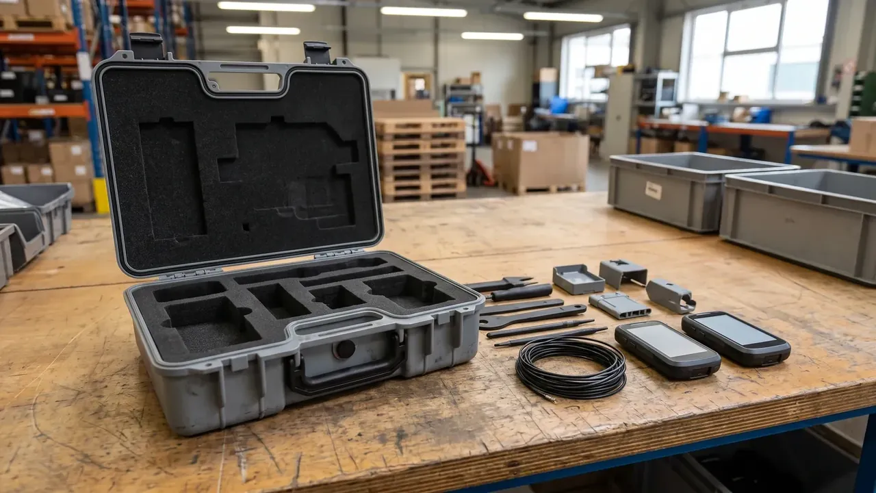
Quick answer: A factory maintenance tool case holds its line over an 800 m push when the caster holes sit 96 mm apart and the count slots open to 72 per cent.
Table of contents
- Moving a Factory Maintenance Tool Case Along the Line
- Caster Hole Pitch and Travel Wander
- Slot Opening Ratio for Tool Counts
- Load Split Between Shelf and Base
- Fixing the Hole Pitch for Inspection Batches
- FAQ
1. Moving a Factory Maintenance Tool Case Along the Line
Push a factory maintenance tool case eight hundred metres and the drift it collects is set by four mounting holes, not by wheel diameter.
The shell measures 540 × 380 × 215 mm outside and 475 × 320 × 155 mm inside, carrying two wrench sets and a meter at roughly 20 kg, past the point where a handle is comfortable. Carrying loads the handle and two latches rated 340 N; pushing loads four casters and the base ribs; pallet transfer loads a flat bottom on a 1200 × 800 mm deck, where casters must recess.
Settle the travel mode before the drawing closes.
2. Caster Hole Pitch and Travel Wander
A 96 mm centre distance between the four holes is what keeps a factory maintenance tool case inside 12 mm of wander across an 800 m route. The pitch fixes the footprint the wheels stand on, and a narrow footprint turns any uneven drag into rotation about the vertical axis.
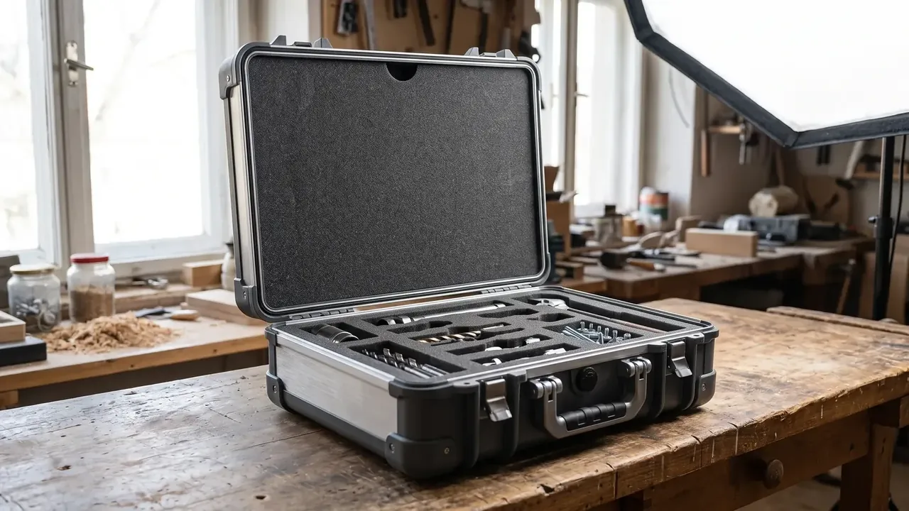
Wheel layout matters more than wheel size. Four swivel casters give the case nothing to hold a heading against and it snakes at walking pace; two rigid front and two swivel rear hold the straight sections and still turn.
Measure it: 800 m line, normal pace, read the offset at 200 m, 500 m and 800 m, keep the largest. Undulation above 3 mm ruins it, so the floor needs flatness better than 2 mm over 2 m. Below 80 mm pitch only 6 mm remains between hole edge and rib root; that band sinks and wander returns past 15 mm.
| Hole pitch tier | Centre distance | Base rib pattern | Wander over 800 m |
|---|---|---|---|
| Wide | 120 mm | Two ribs, one cross rib | Under 8 mm |
| Middle | 96 mm | Closed 5 mm grid | 10–12 mm |
| Narrow | 72 mm | One lengthwise rib | Above 15 mm |
3. Slot Opening Ratio for Tool Counts
Counting slots are where a factory maintenance tool case most often gets one line on a spec sheet. Opening ratio is slot mouth area divided by pocket outline area; at 72 per cent the foam grips the tool and a lifted wrench leaves a gap readable two or three steps away.
Below 60 per cent the foam grips so tightly the tool needs a fingertip to dig out, and nobody returns it. Above 85 per cent a thin lip remains and the tool slides out when the shell tilts. The 72 per cent comes from a 32 mm wrench head in a 23 × 110 mm pocket with 3 mm compression per side.
Foam density has to keep pace. Polyethylene for a factory maintenance tool case runs 45–60 kg/m³; under 45 kg/m³ the pocket edge collapses after a dozen pressings. Pocket depth is 0.8 times tool thickness, and a 72 per cent slot clears with an air gun in 60 s against 90 s at 55 per cent.
4. Load Split Between Shelf and Base
In a factory maintenance tool case the rated 25 kg splits into 10 kg on the upper shelf and 15 kg below, with a 40 mm gap putting the lower centre of gravity over a rib.
Load travels along the ribs. Four caster seats press at the corners, so the base needs a closed perimeter rib tying them together, with a grid carrying load outward. Across a 96 mm span a 4.0 mm base deflects about 0.6 mm under 25 kg evenly spread; at 130 mm it nearly doubles into a visible dip.
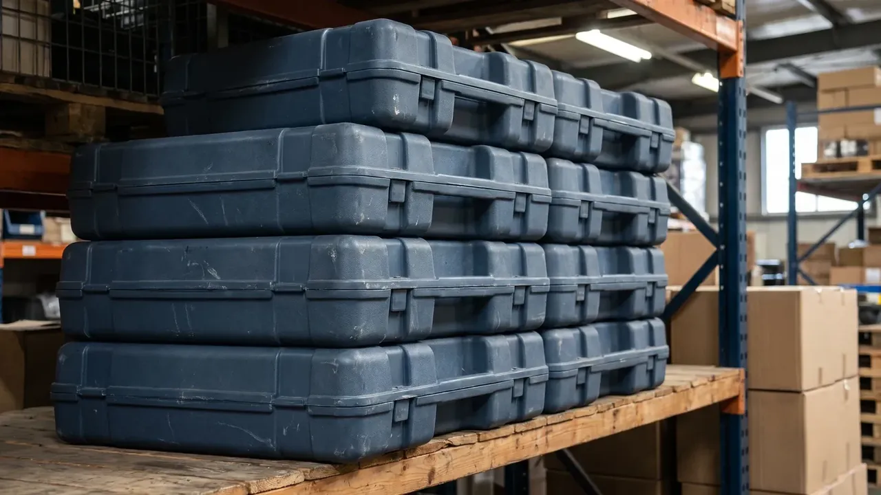
A 540 × 380 mm footprint puts four shells on a 1200 × 800 mm deck, and five high leaves 100 kg on the bottom one. Casters must then recess or come off, or the stack rests on four small wheels and the seat fails first.
| Push distance | Check interval | Allowed shelf sag | Action |
|---|---|---|---|
| 0–200 m | Shift start | Within 0.5 mm | Normal |
| 200–500 m | Weekly | Within 1.0 mm | Log trend |
| 500–800 m | Twice weekly | Within 1.5 mm | Swap shelf |
5. Fixing the Hole Pitch for Inspection Batches
The pitch settles at the shortest tier that holds wander under 12 mm after an 800 m push; narrower belongs on a fixed-station shell. On a factory maintenance tool case drawing it breaks into three lines: 96 mm centre distance to plus or minus 0.15 mm, at least 8 mm from hole edge to rib root, and 0.2 mm flatness across the four holes. Leave one out and the toolmaker rounds the pitch to a multiple of ten.
After 4500 cycles the seats wear and the effective pitch grows about 0.1 mm, so that growth belongs inside the tolerance from the start. IP65 is benchmarked against a 6.3 mm nozzle at 12.5 L/min and roughly 30 kPa, and a shell fresh off an 800 m run carries vibration into gasket compression, which shows first along the base seam.
| Wander reading | Verdict | Disposition | Next batch |
|---|---|---|---|
| Under 8 mm | Best | Release | Same pitch |
| 8–12 mm | Acceptable | Release and file | Double sampling |
| Above 12 mm | Rejected | Back to base mold | Re-cut holes |
Conclusion
A factory maintenance tool case closes on three values: a 96 mm hole pitch, a 72 per cent opening ratio and a 25 kg split over two levels. Each was written back after an 800 m push and a five-high stack.
Related Reading
- Why Hard Cases Beyond Cartons
- Case Assembly Inspection Items and Limits
- Line-Side Tool Case Fixing
- Industrial Tool Case Factory Direct Supply
- Custom Construction Tool Case Factory
Related Products
- 8 Series — Gun Cases; Military Equipment Cases; Camera Equipment Cases; Drone Cases; Watch Cases; Knife Cases; First Aid Cases; Electronics Equipment Cases
- WL8-2812 PP Gun Case — model WL8-2812
- All protective cases and toolboxes: 7 series, 158 models