

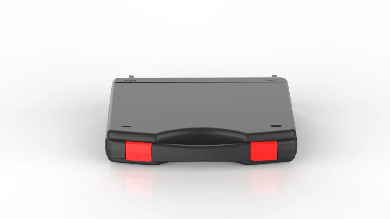
When a blown film line goes down for maintenance, the two parts that come off first are usually the extrusion die and the draw roll. The die has just left a barrel running near 200 degrees Celsius with a layer of semi-solid deposit hanging on the lip, and the draw roll still carries the pressure mark of the last film roll. Months later a spare set has to be ready on the rack, and when it goes back onto the line engineers often find a new scratch across the die lip and a dark line on the roll plating that cannot be polished out. Those marks were not made in production. They were made during a lift, a stack, or an unpacking operation.
JUNZHIJIA treats the die and the draw roll as two entirely different classes of precision part for transport: the die lip faces upward and is held clear of all contact, roll ends rest on dedicated supports, and film debris never shares a cavity with a die lip.
Table of Contents
- Die Lip Deposit Carbonization and the Shutdown Cleaning Cycle
- Identifying and Tracing Die Lip Burr Marks on Film
- Die Temperature Uniformity and Thermal Expansion Allowances
- Draw Roll Coating Wear and Gauge Variation
- Roll Wrap Angle, Speed Ratios and Slip
- Film Static Adhesion and Winding Tension
- Residual Melt Heat Effects on Liners and Seals
- Scratch and Distortion Risks from Inverted Die Placement
- Rust Protection at Roll Ends and Bearing Journals
- Transit Securing of Ionizing Bars
- Compartmented Liner Layouts for Dies and Draw Rolls
- Incoming Inspection: Lip, Roll Face and Journal Checks
- Frequently Asked Questions FAQ
- Conclusion and Related Reading
Die Lip Deposit Carbonization and the Shutdown Cleaning Cycle
A die lip is not an optical component, but what collects on it decides whether the next run is usable. When a polyethylene line is shut down in a controlled way, low molecular weight waxes first precipitate along the lip edges; below 160 degrees Celsius those deposits turn into opaque hard blocks, and below 120 degrees they become a black carbonised shell. Polypropylene yellows much earlier, while polyamide develops a sticky layer from chain scission above 240 degrees. The deposits behave differently, yet the handling logic during transport is identical: remove them while the part is still at the machine, not later in the spare parts store.
| Resin | Deposit appearance | Coking tendency | Shutdown action |
|---|---|---|---|
| --- | --- | --- | --- |
| PE | Waxy translucent hard scale | Medium above 240 C | Drop to 200 C, purge, copper brush and scraper |
| PP | Pale yellow, sticky, stringy edges | High, discolours as it sits | Drop to 190 C, scrape while warm |
| PA | Viscous stringy layer, burnt smell | High, brittle crust above 280 C | Drop to 210 C, clear channel before lip |
| EVOH or PVDC barrier | Black dotted exudation | High | Do not scrub, cool and replace |
Tool choice matters. On the lip, use a copper scraper pushed in one direction along the lip line, never back and forth across it, because repeated transverse scraping cuts grooves into the lip. Clear mandrel deposits with a copper wire brush working along the flow direction, and pick debris out of bolt holes with a bamboo splinter rather than a steel needle, because hard tools leave nicks that later become permanent film defect sources. After cleaning, wipe once with non-woven cloth and medical grade alcohol, let it dry, and pack immediately. Do not leave a cleaned die open overnight; shop humidity usually sits above 60 percent, and a cooling lip in humid air films quickly, and that film runs down to leave water marks.
A six stack blown film line can produce a dozen lip sizes in one major overhaul, and stacked on a bench cross contamination is almost certain. JUNZHIJIA assigns every lip size its own small cavity, with the lip held upward in clear suspension by a matching ring support and no wiping cloth or spare screw placed inside. Precision flat die faces face the same scratch and seating demand, covered in Aluminum Extrusion Die Cases: Die and Stem Component Protection.
Identifying and Tracing Die Lip Burr Marks on Film
A lip burr shows up in production and is easy to misdiagnose. Work the sequence in order: decide whether the mark is fixed in position, decide whether it follows the machine direction, and only then assign a cause. A scratch that stays in the same place across the full width and does not repeat on a cycle almost certainly originates at the die. Dotted marks that drift after every restart point upstream at a chill roll. Evenly spaced short lines along the draw direction, spaced at the roll circumference, are the periodic signature of a roll face defect. The three need different responses: a lip burr gets dressed, a roll defect gets polished or the roll is replaced, and a drifting mark is traced back into the upstream channel.
| Defect shape | Position signature | Cycle signature | Points to |
|---|---|---|---|
| --- | --- | --- | --- |
| Single fixed transverse line | Fixed across full web width | No cycle | Die lip burr or notch |
| Evenly spaced transverse lines | Fixed, changes with gauge | Near roll circumference | Draw roll surface scratch |
| Dotted marks that drift | Random drift | None | Chill roll or shed channel deposit |
| Longitudinal streak | Runs the whole length | Longitudinal | Uneven lip gap flow mark |
| Short scratches at roll edge | Only after winding | None | Film adhering and peeling off the face |
The oldest and most reliable method is the fingertip cross-check: drag a fingertip across the film perpendicular to its surface and judge whether the feel is gritty or slick. Paired with a loupe at 10x or higher, the burr length and direction show whether it was machining residue or service wear. A typical burr of 0.02 to 0.05 millimetres is invisible to the eye and still produces a full-width line on a 30 micron film.
Keep the traceability record. When film inspection finds a line, photograph it and note the roll number and unwind direction, then trace back by roll number, time, die size and operator to the specific die and shift. JUNZHIJIA supplies a packing file including a die lip inspection sheet and a confirmation entry for the previous deposit removal, signed line by line on arrival. That gives both sides a comparable baseline instead of relying on memory when a scratch dispute appears.
Die Temperature Uniformity and Thermal Expansion Allowances
Lip temperature uniformity drives cross-direction gauge variation. Most transverse thickness deviation on a film line comes from the temperature field rather than from the mechanical accuracy of the lip gap. If the centre of the lip runs 3 to 5 degrees Celsius hotter than the ends, flow there is higher and gauge deviation can reach plus or minus 8 percent. On a 1.4 metre wide die, holding full-lip uniformity within plus or minus 1.5 degrees narrows the transverse band to about plus or minus 4 percent.
Thermal expansion has to be allowed for explicitly. Using the 23 times ten to the minus 6 per degree Celsius coefficient for aluminium, a 500 mm lip span grows roughly 0.23 mm when taken from ambient to 200 degrees. If the lip is a split structure, heat pushes it open or pulls it narrower, and the gap reverses as the die cools, so the gauge runs thick for the first minutes after start and only settles after a few hundred metres.
| Temperature band | PE | PP | PA | Lip gap shift, 500 mm cast aluminium |
|---|---|---|---|---|
| --- | --- | --- | --- | --- |
| 120-150 C | Low viscosity, good flow | Beginning to set | Not yet melted | about 0.14 mm |
| 170-190 C | Normal forming window | Lower edge of window | Near melting point | about 0.18 mm |
| 200-220 C | Viscosity running low | Normal window | Normal window | about 0.21 mm |
| Above 240 C | Higher power needed | Melt fracture risk | Degradation begins | about 0.25 mm |
Three layers of response apply. First, zoned heating: the lip gets its own heater band and thermocouple, and heating bands are separated by thermal isolation slots so heat does not bridge between them. Second, assembly allowance: lip and body are assembled cold at the design gap so the hot gap lands inside the target window, a value the die maker states on the drawing rather than something the shop guesses. Third, a controlled cooldown: on shutdown the heaters are stepped down at about 20 degrees Celsius per minute to 120 degrees before free cooling, which avoids twisting the lip through shock cooling.
Temperature uniformity also ties into packing, because residual heat destroys liner preload. Packing a hot part into foam means the foam softens and collapses under the contact area, and once the part cools the liner has lost its support, so in-transit movement lands directly on the lip. Bring the part below 60 degrees Celsius first. Residual temperature management is treated the same way for furnace components in Heat-Treatment Equipment Cases: Furnace and Temperature-Control Component Protection.
Draw Roll Coating Wear and Gauge Variation
Draw roll faces come in two families: hard chrome and ceramic, the latter being silicon carbide or alumina. Hard chrome gives excellent specular finish, a low friction coefficient and a polish down to 0.05 micron Ra or better, but its hardness is modest at roughly 700 to 900 HV, so once a hard particle cuts it the groove keeps extending. Ceramic coatings reach 2000 to 3000 HV and shrug off particle scratching, at the cost of a slightly higher friction coefficient and less specular finish.
The relationship between coating condition and gauge variation runs through a short chain. A groove in the face changes local surface velocity and radius, which changes tension distribution across the web, which appears as periodic gauge variation and as clouding on the wound roll. Diameter tolerance matters just as directly: a diameter error of 0.5 millimetres at 100 metres per minute produces about 0.05 percent line speed variation, which accumulates into measurable gauge deviation.
| Face condition | Ra in microns | How to judge | Effect on film | Action |
|---|---|---|---|---|
| --- | --- | --- | --- | --- |
| Acceptable | 0.10 or below | Profilometer plus visual | Uniform gauge, no lines | Normal service |
| Light wear | 0.10 to 0.25 | Fingertip feels gritty | Occasional short line | Polish and continue |
| Clear scratching | 0.25 to 0.80 | Groove visible under a loupe | Clouding, local film break | Re-chrome or replace |
| Pitting or bare substrate | above 0.80 or base metal seen | Pits under a microscope | Break rate rises, debris | Scrap, fit a new roll |
| Coating delamination | not applicable | Flaking visible to the eye | Particles drop onto film | Stop and clean the die |
Incoming inspection must look at the face under clean side light, running a strip light along the axis of the roll so grooves appear as dark breaks at the edge of the light band. A front-lit photograph will not show them. Check the shoulders and end faces too, because coating blistering always starts at the shoulder.
Dies and draw rolls are the same high cost items in spare parts management, so the liner is configured one set per cavity: two rolls side by side, their ends carried on V blocks, at least 20 millimetres of clearance between working faces, and a foam divider so they cannot rub in transit. Roller fixing and face cleanliness share the logic in Conveyor Roller and Parts Cases: Roller and Drive Component Protection.
Roll Wrap Angle, Speed Ratios and Slip
The wrap angle sets the traction ceiling. Going from 90 degrees to 180 degrees roughly doubles the frictional load capacity through the Euler relation, where traction equals two times web tension times the exponential of friction coefficient times wrap angle over two. For a polyethylene web at a friction coefficient near 0.2 against a metal face, 90 degrees supports roughly 31 newtons and 180 degrees about 96 newtons. That is why draw rolls on high speed film lines are arranged with close to a 180 degree wrap.
Speed ratio mismatch between stages converts directly into gauge change. With a fixed output rate, the ratio of linear speeds across the nip stages sets the longitudinal draw ratio in each section. Raising draw roll speed by one percent raises the draw ratio by one percent and thins the film by about one percent. Transverse gauge is unchanged but orientation rises, so longitudinal tensile strength goes up and heat shrinkage goes up. None of this is a fault by itself, but if an operator trims draw roll speed to compensate a gauge deviation, the result is a chain drift in gauge, speed and orientation.
Slip has three reliable signatures: an abrupt gauge drop, a friction heat mark appearing as a bright or slightly discoloured patch, and a spike in drive motor current. Once slip begins, the web slides against the roll and charge builds sharply, producing punch-through spots that look like fine brown pinpricks, and severe slip gives periodic breaks.
| Symptom | Main cause | Evidence | Response |
|---|---|---|---|
| --- | --- | --- | --- |
| Gauge drops over 3 percent | Draw roll slip | Heat mark plus current spike | Increase wrap, check dancer, clean face |
| Periodic gauge clouding | Speed drift or gear backlash | Period matches roll circumference | Check gear mesh and encoder |
| Brown pinprick holes | Static discharge | Needle sized holes under a loupe | Improve ionising and grounding |
| Periodic film breaks | Face groove plus tension step | Spacing equals circumference | Replace or repair the roll |
| Motor in continuous overload | Poor cooling, high tension | Motor temperature alarm | Clear cooling duct, review setpoint |
Face cleanliness also acts on the friction coefficient. Film debris left on the face behaves as abrasive grit and can lift the coefficient from 0.2 to above 0.35, which looks like extra traction but is actually the prelude to loss of control. That makes pre-packing cleanliness a mandatory clause rather than advice.
Film Static Adhesion and Winding Tension
Polyethylene and polypropylene are insulators, with surface resistance commonly in the 10 to the 9th through 10 to the 12th ohm range. Charge develops as the web peels away from the roll and the stripping roll, through contact and separation, and single-face surface charge can reach the order of one micro-coulomb per square metre. Accumulated at the winding end it produces static adhesion: layers stick tightly, the web sits off centre on the core, and the tension sensor reading drifts.
Different resins charge differently. In the usual triboelectric series, PE and PP sit at the negative end, so film that has contacted a metal roll carries negative charge, while PA sits closer to neutral. Films with heavy masterbatch addition and differing levels of slip agent and antistatic agent can differ by a factor of three to five in charging behaviour, so the same line can behave completely differently after a formulation change. That shift is frequently misreported as an equipment fault.
| Symptom | Evidence | Trigger | Direction |
|---|---|---|---|
| --- | --- | --- | --- |
| Layers stick, unwinding tears | Peel force rises | High surface resistance, no vent path | Lower tension, add ionising |
| Off-centre winding | Sensor swings side to side | Static repulsion plus skew | Check bar position and grounding |
| Regular brown pinprick holes | Discharge punch-through | High potential, local air gap | Raise ionising capacity |
| Nip roll slipping | Adhesion exceeds torque | Static plus low friction | Fix the static source, not tension |
| Flapping at the roll edge | Layer tension mismatch | Static plus core runout | Recentre core, tune taper |
The ionising bar is itself a precision item needing dedicated protection. Its quartz discharge tube has a wall thickness of only 1 to 1.5 millimetres; once it shatters the bar loses gas tightness and the glass fragments drop onto the film as bright defect points. During handling, always grip the bar away from the discharge tube, support the insulator base, and never lift it by the top end. Supporting programme requirements are set out in Anti-Static Component Boxes and Electronic-Part Protection: ESD Standards.
The winding tension target is a constant wound density, not a constant tension. Tension that is too high leaves a hard impression at the core, which later shows as a burst edge when the roll is slitted. Too low leaves the core loose and the ends ragged. A practical starting range is about 8 to 15 newtons per metre of width at a 150 millimetre starting roll diameter, falling to 3 to 6 newtons at 400 millimetres, and it must be calibrated by measurement after start-up.
Residual Melt Heat Effects on Liners and Seals
Residual heat from a part that just came off the line is the most frequently ignored packing risk. At shutdown a PE die typically still sits between 170 and 200 degrees Celsius, and a draw roll face, continuously rubbed by film, can reach 60 to 80 degrees. Close a case around that and the foam softens, the gasket ages quickly, and the desiccant saturates ahead of schedule.
| Part | Residual temperature | Consequence of contact | Correct handling |
|---|---|---|---|
| --- | --- | --- | --- |
| Die body | 150-200 C | Foam collapses, preload lost | Cool below 60 C before packing |
| Die lip | 160-210 C | Foam scorches, sticks to liner | Suspended, no foam contact |
| Draw roll barrel | 60-80 C | Foam compresses permanently | Thermal barrier, air cool |
| Roll ends | 40-60 C | Grease loss, condensation | Cool, regrease, seal against rust |
| Ionising bar | 40-60 C | Stress on the discharge tube | Cool before fixing in the cavity |
The cooling method itself needs judgement. Natural cooling is slowest but applies the least stress. Forced air creates a fast local temperature gradient across the lip and can twist it. Water cooling is fastest and the most dangerous, because quenching a hot die can crack it. A two stage approach works best: let the part stand until it reaches about 120 degrees Celsius, then force air down to 60 degrees. That controls total time while avoiding quench shock.
Low and high temperature behaviour must be kept separate. In the cold, foam turns hard, EVA shrinks and gaskets become brittle. In the heat, foam softens and gasket expansion can add to air pressure inside the case. If a case has sat in a hot environment, such as a container in summer sun, opening it immediately after arrival can let internal pressure push the seals apart, which is why a pressure equalisation valve earns its place here. Selection guidance sits alongside the grounding and discharge requirements in Anti-Static Component Boxes and Electronic-Part Protection: ESD Standards.
Scratch and Distortion Risks from Inverted Die Placement
The most common single mistake on the shop floor is finishing a lift and then resting the die with its lip face down on a bench or pallet. One such action produces three distinct types of damage.
The first is direct lip contact with the bench, where machining tool marks and burrs form a line contact and squeeze out of shape, immediately changing the lip gap distribution. The second is that with the die inverted, debris and metal chips fall naturally into the die cavity, and on the next start they enter the melt stream and leave an impression in the mandrel. The third is that inverted, the weight sits on the seating shoulder, and if the liner has no ring support one side of the lip takes sustained load and does not spring back on cooling, putting lip flatness out of tolerance.
| Orientation | Lip condition | Debris entry | Flatness risk | Verdict |
|---|---|---|---|---|
| --- | --- | --- | --- | --- |
| Lip up in a ring support | No contact | Debris in cavity floor | Low | Acceptable |
| Lip up against a lid liner | Sustained contact | Debris pressed into lip | Medium | Not acceptable |
| Lip down on a bench | Line contact, easy to crush | Chips land on the lip | High | Reject outright |
| On edge, not load bearing | No contact | Debris collects at side | Medium | Acceptable if tied down |
A sound arrangement has three requirements. The lip faces upward. The lip cavity is held clear, with the weight taken by a ring support coaxial with the lip, machined from EPP or high density EPE and preferably cut with a recess matching the lip outline so the lip sits inside a shaped pocket rather than pressing on a flat plane. The assembly is fixed inside the case and the case itself no longer moves inside the vehicle or during stacking. Anti-tip fixing matters most outdoors or on rough routes, because a plated face dragging against bare metal generates fine debris.
Leave a debris path inside the cavity as well. Fit a removable chip trough below the lip so that unpacking pulls the chips out with it instead of leaving them sitting in the cavity for good. This detail matters most on polyamide lines, where degraded material becomes extremely adhesive once it meets moisture.

Rust Protection at Roll Ends and Bearing Journals
The roll ends and bearing journals are the part of a film extrusion line that quietly fails in transit. The reason is straightforward: the working face is protected by hard chrome or ceramic and looks durable, while the ends and journals are bare carbon steel or 40Cr alloy steel. Once rust protection is not addressed, the bearings corrode and the roll becomes scrap within a few months after arrival.
Corrosion usually starts when moisture is trapped inside the cavity. A roll coming off the line may carry washing fluid and residual water. Sealed straight into a case, that water is held against the steel and forms an electrochemical cell. A common field failure is air conditioning in the shop pulling the cavity to nearly 100 percent relative humidity, so that by the next morning the journal already shows pitting.
| Step | Method | Acceptance criterion |
|---|---|---|
| --- | --- | --- |
| Clean | Non-woven cloth, neutral detergent on face and ends | No visible debris or oily sludge |
| Dry | Compressed air then free air drying | No water film at the journal |
| Protect | Grease or vapour corrosion inhibitor on ends | Continuous film, no missed patches |
| Seal | Dust caps on ends, desiccant in the cavity | Journal isolated from the cavity |
Neutral salt spray testing to GB/T 10125 can compare protective schemes. It is worth stating honestly that salt spray serves process comparison and screening; it cannot be converted directly into field service life. Wider treatment of precision fit surfaces appears in Bearing and Gearbox Cases: Precision Fit Surface and Grease Protection.
Another easily missed point is scoring on the journal. Rust pits in a bearing seat let an assembly appear correct while the roll runs eccentric. An eccentric draw roll produces gauge variation directly, and that deviation may only surface months after commissioning. The journal should therefore receive a fit surface check and a paper seal before packing.
Transit Securing of Ionizing Bars
The ionising bar is usually treated as an accessory and dropped into the bottom of the case. On a film extrusion line that is clearly wrong, because it is a glass tube assembly needing at least three points of flexible restraint so transit shock does not break, disconnect or shake it loose.
A typical ionising bar is a quartz discharge tube on an insulator base with a high voltage cable termination. Three failure modes occur in transit. The tube fractures under vibration, leaving a fine conchoidal break and small fragments. The base cracks under impact, usually at the thread root or the claw. The cable pulls out of its termination or breaks at a bend. All three leave a bar that looks intact on the bench and produces no ions on the line.
| Failure mode | Signature | Detection method | Action |
|---|---|---|---|
| --- | --- | --- | --- |
| Tube fractures in vibration | Fine conchoidal break, fragments | Full length against light, tap gently | Replace, never bond |
| Base cracks | Whitened crack at thread root or claw | Visual plus gentle twist check | Replace the base |
| Cable pulled out | No strain relief, cable hangs loose | Re-check connection | Re-terminate and relieve |
| Electrode wire displaced | Wire shifted toward the shell | Only on dedicated equipment | Return to the manufacturer |
Packing requirements are specific. Give the bar its own cavity, with foam shaped to the tube profile so support is continuous around the full circumference. Add flexible restraint at both ends, applied as a tie without squeezing. Coil the high voltage cable in a gentle loop at the corner of the cavity, clear of the tube itself. Do not put desiccant in that cavity because of the high voltage insulation requirement, and do not wrap it in metal shielding.
The general electrostatic framework for surface resistance, grounding continuity and discharge time is a shared standard, but for the ionising bar itself the manufacturer installation instructions take precedence. Its packing priority shares a logic with Optical Lens and Coated-Element Cases: Cleanroom and Scratch Protection: what is protected is surface condition rather than structural strength.

Compartmented Liner Layouts for Dies and Draw Rolls
The first principle of liner design is that locating is carried by a rigid base, cushioning by a compressible layer, and the load path must not run through soft foam. Liner sets for film extrusion parts are usually built in three layers.
The lowest layer is a load bearing base, machined from expanded polypropylene or high density EPE, taking the combined weight of die and rolls and transferring it directly to the case floor or to a load beam. The middle layer is the locating cavity, compressible foam cut to the part outline with compression held between 10 and 25 percent of the original thickness. The top layer is a restraint layer that stops the part lifting upward under impact.
| Part | Locating method | Permitted movement | Foam compression | Key constraint |
|---|---|---|---|---|
| --- | --- | --- | --- | --- |
| Die body | Coaxial ring base | Zero vertically | 10-15 percent | Lip clear, no debris |
| Draw roll barrel | V blocks under the journals | Zero vertically | 10-20 percent | 20 mm between faces |
| Roll ends | Dedicated bored positions | Zero | 10 percent | Rust coating, dust caps |
| Ionising bar | Circumferential foam fit | Zero | 15-20 percent | Flexible restraint, looped cable |
| Heater bands, thermocouples | Small separate bags | Up to 5 mm | 30 percent | Cables must not be loaded |
Dimensional tolerances for roll cavities deserve explicit comment. Roll working diameters commonly run from 200 to 800 millimetres, so a clearance of 3 to 8 millimetres between the liner bore and the roll is reasonable, but a generous clearance destroys location and lets the roll move inside its cavity during transit, dragging the working face across the foam to generate fine debris. Smaller clearance is therefore better, but enough room must be left for thermal expansion, since a roll leaving the line runs more than 40 degrees Celsius above ambient.
Tolerances for the die cavity matter more, because the fit between lip and liner directly controls how the lip is loaded. The recommended approach is a pocket machined to match the die lip outline so the lip drops into a shaped recess, so that even a 20 gram lateral impact cannot squeeze the lip sideways. Cleanliness requirements rise accordingly: no fibre-shedding material is permitted there, because a single fibre trapped in the lip gap is enough to produce a flow mark. Foam density and thickness follow the usual cushion derivation set out in GB/T 4857 Transport Packaging Testing for Protective Cases.
Incoming Inspection: Lip, Roll Face and Journal Checks
Arrival inspection has to run in a fixed order, because a different order leads to wrong conclusions. First check the outside of the case: impact marks, water ingress traces, abnormal centre of gravity shift and stacking compression marks, and confirm the latches are in their transport lock state. Second check that the gasket and pressure equalisation valve are intact and that no spontaneous opening occurred. Only then open the case. Once open, the three part families each have their own checklist.
| Part | Check item | Method | Pass criterion | Action if failed |
|---|---|---|---|---|
| --- | --- | --- | --- | --- |
| Die | Lip burr, notch, crush mark | Loupe at 10x plus fingertip check | Unbroken lip, no gritty feel | Return for repair |
| Die | Deposit in the cavity | Visual with a side light | Clean, trace residue only | Clean and record |
| Die | Lip flatness | Optical flat or laser meter | 0.05 mm or better | Repair |
| Draw roll | Scratches, grooves, pitting | Strip light plus profilometer | Ra 0.10 micron, no groove | Polish or replace |
| Draw roll | Blisters or delamination | Visual | None present | Stop and refer for inspection |
| Draw roll | Corrosion at the ends | Visual plus white cloth wipe | No rust on cloth, no pitting | Re-coat and re-inspect |
| Ionising bar | Tube integrity | Full length against light | No cracks, no fragments | Replace, never bond |
| Ionising bar | High voltage termination | Manual re-check | Secure with strain relief | Re-fix |
| Full set | Packing file matches contents | Item by item count | Complete part numbers and documents | Complete before stock entry |
The principle when a problem is found is to record it and photograph it on the spot, not to accept the delivery first and sort it out later. Comparing physical condition against the packing record shows whether damage happened in transit or during packing. If case crush marks and part damage do not correspond in position, the liner load path is usually the real problem, and the fix belongs in the liner design rather than in repairing the part.
Record acceptance data for each batch back into the packing record sheet as input to the next batch. When one failure type keeps repeating, adjust that link: repeated lip scratches usually mean the shaped pocket in the lip support is not accurate enough, and repeated end corrosion usually means the desiccant quantity or the closing timing was wrong.
Frequently Asked Questions FAQ
Q: The die comes off the machine straight into its case. Will 200 degree residual heat destroy the foam?
A: Yes, and the mechanism is usually softening and collapse rather than outright burning, which makes it harder to detect. Expanded polyethylene foam melts somewhere between 90 and 110 degrees Celsius, but sustained contact with a local zone above 150 degrees causes viscous flow first, leaving dents and hollows in the surface. Once the liner has softened, the designed 10 to 20 percent preload is gone, the part loses its restraint inside the case, and in-transit movement lands directly on the lip. The correct procedure is a two stage cooldown: let the die body stand until it has come down naturally to about 120 degrees Celsius, then force air down to below 60 degrees and pack. The natural stage above 120 degrees must not be skipped, because quenching the lip creates thermal twisting that only shows up as cross-direction gauge variation after the die is back on the line. Even below 60 degrees the lip must not touch foam at all; it has to be held clear by the ring support, and that clearance is the single most important line in the packing instruction.
Q: How many handling cycles can a draw roll coating survive, and is there a usable cycle number?
A: There is no usable cycle number, only condition criteria, and that is the defining feature of protecting a roll. Hard chrome fails by a single event rather than by gradual wear: one 0.05 millimetre groove is already visible on the film, and no number of additional cycles compensates for a single incident. Roll management therefore shifts from how many times it may be handled to what it may touch. Build a contact whitelist: foam liner, nylon lifting sling and soft cotton cloth are acceptable; steel bars, bare metal benches and stacked roll faces are not. Deciding whether a face needs polishing or replacement also ignores cycle count and uses measurements instead. Once Ra passes 0.10 micron, or a continuous dark line appears under the strip light, the face enters the polishing or replacement process, and the decision is recorded against the roll serial number rather than against a date. That serial-based record is what lets a later film defect be traced back to a specific roll rather than to a handling count.
Q: Film static adhesion is severe. How much of that can packaging solve, and what handles the rest?
A: Packaging mainly addresses debris and friction-induced charging; the rest has to be solved on the equipment side. Its real value is that isolating the die and the face prevents grooves from being cut, and grooves feed static adhesion, so the two problems reinforce each other if left alone. On the equipment side, work in order: check grounding first, then ionising capacity, and only then consider reducing tension. The ionising bar must be matched to the actual web width in height and coverage, and the most common error is a bar that is too short, so the edges receive no ions and edge tension stays low, which makes the core run off centre. Confirm the generator output as well, because a damp bar or a wrong mounting angle can cut discharge efficiency sharply and leave the line convinced the bar is healthy. A periodic discharge check against a known target keeps the bar honest, because a healthy-looking bar with low output is the most common hidden cause of edge tension problems.
Q: Must the die and the draw roll travel in the same case, and what do separate cavities buy?
A: They must be separated, at minimum by separate cavities, and both reasons are practical. On debris, any degraded polyamide material or polypropylene gel that sheds from the die cavity and lands on a roll face is a bright defect that can never be cleaned off. On loads, the weight and swinging inertia of a draw roll transfer through the liner to the neighbouring die cavity, pushing on the lip gap from the side. Once split, each cavity can be designed around its own thermal expansion coefficient and weight: the die cavity solves lip suspension and chip collection, the roll cavity solves end support and face clearance. Splitting also improves parts control, because dies and rolls have completely different quantities, service lives and inspection items, so mixed cases cannot be counted part by part while separate cases can be registered one code per piece with a full packing record behind each one.
Q: A die lip already has a light burr. Will transport make it worse if nothing is done?
A: Yes, and the mechanism is straightforward. On the line a lip burr softens in the melt to some extent, but during transport it is a hard metal projection and the first thing in the cavity to touch anything. The typical deepening sequence runs like this: the burr scores the foam surface, the score forms a groove, debris collects in that groove, the debris is pushed into the burr root on the next packing, and the burr then breaks off in transit vibration. The break face is sharper than the original burr and sits closer to the centre of the lip. Once on the line, that sharp break face sheds periodically, and each shed piece becomes one bright point or one filament break in the film. The acceptance rule is absolute: any lip that registers gritty in a fingertip cross-check should not enter transport before it is dressed, polished and cleaned.
Q: Can temperature swings in transit degrade the liner, and how much desiccant belongs in the case?
A: Yes, but the mechanism is often misread. The swing itself does not destroy foam. The path is temperature swing, then cavity relative humidity change, then condensation, then moisture uptake by the material or corrosion of the metal. For the parts in this article the real risks are journal corrosion and moisture on the ionising tube. Desiccant quantity must not be guessed from habit; it is calculated from three inputs: net cavity volume, the air exchange allowed by the sealing class, and the transit period. A practical starting point is 8 to 12 grams per litre of cavity, adding about 30 percent margin to cover repeated openings. Place a humidity indicator card alongside the desiccant and read the card before opening on arrival. If the card is out of range, do not open the case, mark it and move it to a dry room to rebalance. Rebalancing before opening prevents the very corrosion the desiccant was meant to stop, and the card reading is the only field proof the charge did its job.
Q: How should lip dimensions be rechecked after unpacking when there is no gauge on site?
A: Start by being clear about what is being checked. Lip gap is a die maker's factory specification, and the transport case is responsible for holding that state unchanged, not for re-machining the die on site. Site verification exists to detect transport distortion, and there are three tiers. The first is visual plus fingertip cross-check to confirm no new crush mark or burr. The second is a feeler gauge check on the die body flange gap, taken at the four corners and four midpoints of the lip; if those readings differ by more than 0.1 millimetres the assembly has moved. The third, where conditions allow, is an optical flat or a laser distance meter across the lip. Quantifying transport distortion depends entirely on a pre-packing baseline, so the packing file should include lip condition photographs and key measured dimensions taken before closing. Without that baseline, only new damage can be judged.
Q: A fixed scratch line appears in film inspection and survives every corrective action. How is the real source traced?
A: Work in four steps. First confirm the line is genuinely fixed: watch three consecutive rolls; if the line position is identical across web width the source is a fixed geometry, almost always the die. If it drifts with the roll, the culprit travels with the material. Second, run an elimination test: fit a complete set of spare draw rolls and run one film roll; if the line disappears the fault sits in the roll train, and if it survives new rolls it sits at the die or upstream. Third, analyse the periodicity: count scratch lines on one roll and compare their spacing against roll circumference and any die cavity dimension, and the cycle itself points at the source. Fourth, reproduce the contact: take a retained sample of the same film and drag a hard-edged block along the suspect lip edge to see whether the same line form appears. If all four steps still leave it unresolved, the defect comes from gels or contaminants in the melt, and the giveaway is that it wanders with the melt rather than staying fixed.
Conclusion and Related Reading
Dies fear scratches, debris and residual heat; rolls fear abrasion, corrosion and static. JUNZHIJIA supplies integrated structural tooling, custom liner moulding, latch selection, OEM and ODM delivery and the full document set, because no single packing logic covers both part classes.
Related Reading