


The core job of a blown-film and cast-film equipment case is to protect two component groups that look robust but carry extreme precision: die heads and rollers. The critical precision of a die head lies in the die lip gap, commonly between 0.5 mm and 2 mm and smaller on ultra-thin film lines, with lip gap uniformity measured in microns. The critical precision of a roller lies in its surface, where the roundness, cylindricity, and dynamic balance of a chrome-plated mirror roller, a rubber-covered roller, or a PTFE roller directly determine film thickness uniformity and surface quality. Both groups share the same weakness: visible damage is easy to spot, but precision damage is invisible and typically only surfaces after installation, as transverse thickness deviation, surface streaks, or uneven winding. The correct approach is therefore to split protection into three measurable lines: isolate lip gaps and flow channel surfaces from any hard contact with high-precision inserts; preserve roller roundness and dynamic balance with V-cradles, clamps, and multi-point axial support; and keep transport vibration, impact, corrosion, and dust out through peak acceleration control and temperature and humidity management.
In real film plants, die heads and rollers are most often damaged in the interval between product changeovers. When a blown-film line changes specification, the die head is lifted off as a unit and set temporarily on the workshop floor. When a cast-film roller is removed for re-covering or overhaul, it is laid on a pallet for transport, the roller surface contacts the pallet edge, and a single mark becomes a continuous longitudinal streak on the film after restart, requiring regrinding or re-covering to resolve. These losses look small individually, but because they persistently affect yield, the real cost is far higher than expected. This article is written for equipment engineers, spare-parts storekeepers, and purchasing staff at film producers, and sets out die head precision protection, roller surface protection, anti-vibration practice, and verification standards in a form that can be written directly into a technical agreement.
Table of Contents
- 1. Precision Sensitivity Points in Blown-Film and Cast-Film Equipment Parts
- 2. The Die Head: Lip Gap, Spiral Mandrel, and Flow Channel Surfaces
- 3. Die Head Heating: Heater Bands, Thermocouples, and Junction Boxes
- 4. Rollers: Chrome Mirror Finish, Rubber Covering, and Dynamic Balance
- 5. Anti-Vibration for Precision: Peak Acceleration, Drop Height, and Cushion Thickness
- 6. Case Structure and Inserts: V-Cradles, Clamps, and Axial Support
- 7. Environmental Control: Moisture, Dust, and Static
- 8. Protecting Thin-Wall Components: Air Rings, Bubble Stabilisers, and Collapsing Frames
- 9. Standards and Verification: IEC 60529, GB/T 4857, ISTA, and ISO 4406
- 10. Selection Process and Common Misconceptions
- 11. Incoming Inspection and Routine Maintenance Checklist
- Frequently Asked Questions
- Conclusion & Related Reading
1. Precision Sensitivity Points in Blown-Film and Cast-Film Equipment Parts
Before choosing a case, identify which surfaces will affect film quality if they move. The precision sensitivity points on a blown-film or cast-film line cluster in five groups.
| Sensitivity group | Representative parts | Symptom after disturbance | Direct implication for protection |
|---|---|---|---|
| --- | --- | --- | --- |
| Gap-type precision | Die lip gap, die ring gap, internal cooling air ring gap | Transverse thickness deviation, thick and thin bands, local thinning | No compression, no impact on the lip edge, fixed orientation |
| Surface-type precision | Chrome mirror rollers, rubber-covered rollers, PTFE rollers, cooling rollers | Longitudinal streaks, pitting, uneven winding | Full-length soft facing, no contact with hard objects |
| Flow channel precision | Spiral mandrel, distribution channels, extruder head channels | Uneven melt distribution, local degradation, black specks | Flow channel ports plugged, dedicated compartments, rust prevention |
| Dynamic balance precision | High-speed take-off rollers, winding rollers, guide rollers | High-speed vibration, noise, film flutter | Prevent local marks, prevent shaft end impact, axial support |
| Heat transfer precision | Heater bands, thermocouples, thermal oil connection ports | Uneven temperature, control drift, leakage | Restrain leads, plug ports, protect seal grooves |
The most important distinction in this table is between gap-type and surface-type precision. Gap-type damage tends to be an out-of-tolerance condition, while surface-type damage tends to be localised, and the two are verified in completely different ways. A change in die lip gap affects the thickness distribution along the entire circumference and is a full-width problem. A mark on a roller surface is local, but it repeats on every rotation and produces a periodic streak.
Another frequently overlooked point deserves emphasis: a significant share of die head and roller damage comes from static compression rather than impact. A die head placed on an uneven floor, a roller resting on a pallet edge, a die head stacked on another die head: none of these create a large impact, but each applies a sustained load that eventually produces irreversible distortion or marking. A blown-film and cast-film parts case must therefore deliver both impact resistance and resistance to sustained compression, and the latter is usually harder to achieve.
2. The Die Head: Lip Gap, Spiral Mandrel, and Flow Channel Surfaces
The die head is the core component of a blown-film line and a first-class protected object here.
2.1 The Die Lip Gap: Micron Precision, Two Destructive Forces
The die lip gap sets the initial film thickness. It fears two forces above all: localised plastic deformation from impact, and creep from sustained compression. The first typically happens when a lip edge strikes a hard object during lifting. The second typically happens when a die head lies on an uneven surface or carries other items on top. Both appear as a lip gap that is no longer uniform, and both require disassembly, readjustment, or regrinding to correct.
Three requirements protect the lip:
- Fit an annular soft cap over the lip end face, with an inner diameter slightly larger than the lip, so no hard edge ever presses on the lip itself.
- Never stack die heads inside the case, and never allow other spare parts or the closing pressure of the lid to bear on the head.
- Never place the lip face down. For the same reason that a rubber mold parting line must face up, a precision face must not become a load-bearing face.
2.2 The Spiral Mandrel and Distribution Channels
The spiral mandrel and distribution channels spread melt evenly around the full annulus. Their internal surfaces are typically polished or chrome plated, and any score creates local residence where material degrades during prolonged high-temperature dwell, appearing in the film as periodic black specks or gels. Flow channel openings must therefore be fitted with soft plugs, the head must occupy its own compartment, and rust prevention must be completed before storage.
On rust prevention, die head bodies are usually alloy steel, and flow channel dead corners corrode readily in humid conditions. A three-layer system is recommended: a thin oil film, a vapour-phase corrosion inhibitor, and desiccant, holding internal relative humidity below 60 percent with an ideal band of 40 to 55 percent, plus attention to condensation caused by temperature differentials. The underlying principle is discussed in the note on how protective cases handle temperature extremes.
2.3 Die Head Support and Orientation
| Support method | Description | Advantage | Risk | Selection guidance |
|---|---|---|---|---|
| --- | --- | --- | --- | --- |
| Full base support | The machined base plane rests on a flat pad over its whole area | Even loading, stable orientation | Requires a machined base plane | Preferred solution |
| Annular support | Support at the flange face or an annular boss | Convenient for upright storage | Bearing area must be sufficient | Used when stored upright |
| Three-point support | Location on three blocks | Easy to align | Unequal block height distorts the head | Only for small die heads |
| Suspended on straps | Hung inside the case from slings | None | Swings and strikes the case; absolutely forbidden | Never use |
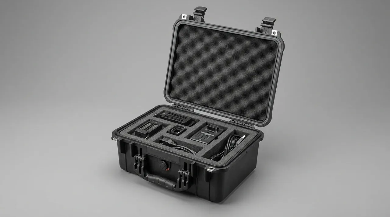
One practical rule applies: inside the case, a die head should be supported, not clamped. Clamping a die head creates local stress near the lip or flange face, and long-term storage can induce slight distortion. The correct approach is to let the head rest over its full base area in a matching cavity, with soft restraint blocks around it to limit horizontal movement but no clamping force.
3. Die Head Heating: Heater Bands, Thermocouples, and Junction Boxes
The heating system looks like an accessory, but it is the foundation of temperature control on a film line and deserves separate treatment.
3.1 Heater Bands
The most common damage to ceramic, mica, and cast aluminium heater bands in transport is cracking of the ceramic body and breakage of the internal resistance wire. The cause is usually not impact but internal fatigue from drops and vibration, plus shell deformation from compression. Protection points: heater bands belong in their own compartments, cushioned all round, never sharing with heavy parts, and never stacked.
3.2 Thermocouples and Compensating Leads
The thermocouple itself is small, but its compensating lead is the weak point. Repeated sharp bends and pulling break the conductor internally, showing up as a jumping temperature reading or an open circuit. Protect them by coiling the leads into a generous loop, securing them with soft ties, keeping tie contact away from metal edges, fitting sleeves at connectors, and storing the whole bundle in a dedicated compartment away from heavy parts.
3.3 Junction Boxes and Electrical Components
A die head junction box contains terminal strips, terminals, and sensor interfaces. Two protection points apply: moisture, since dampness lowers insulation resistance, addressed with desiccant and a humidity indicator card inside the case; and static and dust, since dust entering terminals causes poor contact, addressed using the approach described in the note on ESD shielding design for protective cases.
3.4 Suggested Accessory Provisioning
In practice, a die head case usually carries more than the head itself: several heater bands, several thermocouples, gaskets and bolts, and dedicated tools. Design separate small compartments with standardised label areas for these accessories rather than wedging them into gaps beside the head. Two reasons: it prevents small items from becoming impact sources in transit, and it makes a missing item obvious during a changeover. The same reasoning underlies the removable divider system for protective cases.
4. Rollers: Chrome Mirror Finish, Rubber Covering, and Dynamic Balance
Rollers are the most numerous and the most varied in unit price among cast-film and blown-film components, and they form the second main line of this article.
4.1 Three Roller Surface Types and Their Weak Points
| Roller surface | Surface character | Main damage form | Protection point |
|---|---|---|---|
| --- | --- | --- | --- |
| Chrome mirror roller | Hard, smooth, extremely low roughness | Scoring, edge flaking of the plating, pitting | Full-length soft facing, no contact with hard objects |
| Rubber-covered roller | Elastic, relatively soft | Compression marks, cuts, covering debonding, aging | Avoid sustained compression, oil, and ultraviolet light |
| PTFE roller | Non-stick, relatively soft | Scoring, local indentation | Avoid sharp objects and sustained point loads |
| Cooling roller | Internal water channels | Surface scoring, channel corrosion | Surface facing plus drainage and capping |
| Guide and take-off rollers | High-speed rotation | Affected dynamic balance | Prevent local marks and shaft end impact |
4.2 The Real Enemy Is a Sustained Point Load
Rubber-covered rollers develop irreversible compression marks under sustained point loads, and those marks cause film flutter and thickness variation while running. Chrome rollers are hard, but a sharp hard object under sustained pressure still produces a mark or flaking of the plating. Support method is therefore critical:
| Support method | Contact character | Effect on the roller surface | Recommendation |
|---|---|---|---|
| --- | --- | --- | --- |
| Flat pad | Line contact | Prone to linear marks | Not recommended |
| V-cradle, two-line contact | Two generatrix lines | Load concentrated; marks still possible | Acceptable for short transit |
| Conforming half-round cradle | Area contact, distributed load | Lowest stress | First choice for long and high-precision rollers |
| Clamp plus axial restraint | Area contact plus axial fixing | Prevents both rolling and axial travel | Recommended for heavy and long rollers |
| Shaft-end support with a mid cradle | Supported at journals and mid-span | Roller surface untouched | Best solution for long, high-precision rollers |
One important conclusion follows: for long, high-precision rollers, the ideal arrangement supports the roller at its journals so the surface carries no load at all. This requires bearing-seat style supports in the case at each shaft end, with a mid-span cradle to prevent sagging. The roller surface then contacts nothing along its whole length and needs only a dust sleeve, which keeps precision risk at a minimum. Where no usable journal exists, the next best option is a conforming half-round cradle with blocks tangent along the full length and matched in height.
4.3 Axial Location and Movement Prevention
The most common transport failure for rollers is axial travel. When the case tilts or vibrates, the roller rolls or slides on its cradles and a shaft end strikes the case wall, damaging the shaft face and bearing seat. The remedy is axial restraint blocks at both ends with 1 to 2 mm clearance, plus soft sleeves on the shaft ends. Restraint blocks must press on a journal or an end face, never on the roller surface.
4.4 Internal Water Channels
Cooling rollers contain water channels. Before storage, drain them, blow them dry, and cap the connections. If water remains long term, corrosion products block small passages, causing uneven cooling and film thickness variation. Where a roller is fitted with a rotary joint, that joint is a precision seal and should be packed separately with a protective cap.
5. Anti-Vibration for Precision: Peak Acceleration, Drop Height, and Cushion Thickness
A film equipment parts case must control more than whether something breaks. It must limit the shock transmitted to the part so that the part stays within its precision limit.
5.1 Peak Acceleration Is the Core Metric
The severity of shock damage depends mainly on the peak acceleration transmitted to the part. The physical relationship is simple: for the same shock energy, a longer deceleration distance means a lower peak acceleration. The compression of a cushioning material provides that deceleration distance and flattens the peak. The difference between a hard case transmitting force directly and a thick cushion flattening the peak is therefore not a matter of feel but a difference measured in orders of magnitude.
5.2 Three Practical Criteria
- Minimum cushioning thickness around the part should be 20 to 30 mm, with cushioning also at the base and lid. No part should touch a case wall.
- Cushioning contact area must be sufficient. Calculate against the allowable contact pressure of the interface, and keep contact pressure at sensitive locations such as lip edges and roller surfaces well below the material's allowable value.
- The system natural frequency must avoid the dominant excitation band. For heavier rollers that are sensitive to vibration, choose softer, thicker cushioning with better damping to push the natural frequency down.
5.3 Repeated Impacts and Material Fatigue
Transport is not one impact but hundreds or thousands of small ones. Cushioning materials need repeated-impact resistance and good compression recovery. Three checks help: how crisply it rebounds after pressing, since soft, weak rebound usually indicates low density; whether compression set appears after repeated loading, since a material that will not recover is near end of life; and whether edges tear or shed debris, which indicates that location is seeing friction and impact beyond design. EPP is known for shape recovery and suits repeated handling and long-term vehicle vibration. EVA rebounds well and machines precisely, making it suitable for load-bearing cavities and facings. Ordinary open-cell sponge collapses under heavy load and should not be the primary load-bearing material. Material comparisons are covered in the note on foam material comparison for protective cases and in internal cushioning design for protective cases.
6. Case Structure and Inserts: V-Cradles, Clamps, and Axial Support
Translated into structure, die head and roller case design reduces to four structural elements and four material families.
6.1 Four Structural Elements
| Element | Function | Key design point | Common error |
|---|---|---|---|
| --- | --- | --- | --- |
| Die head locating cavity | Supports the base, limits horizontal movement | Cavity face conforms to the base; finger recesses provided | Clamping the head, creating local stress |
| Roller cradle block | Supports the roller and distributes load | Half-round conforming, tangent along full length, matched height | Too few supports, allowing mid-span sag |
| Axial restraint block | Prevents axial travel | Presses on journal or end face, 1 to 2 mm clearance | Pressing on the roller surface, leaving a mark |
| Shaft end bearing seat | Leaves the roller surface load-free | Matches the journal; soft liner can be added | Seat bore too hard, scuffing the journal |
6.2 Material Selection
- Load-bearing structure. Engineering plastic board, composite board, or a metal frame carries the primary load and prevents long-term distortion.
- Soft facing. EVA or expanded polyurethane forms the contact layer against roller surfaces and die lips to create soft contact.
- Cushioning layer. EPP or EVA absorbs energy, with density selected from part mass and sensitive frequency band.
- Sleeves and caps. Soft EVA or expanded material for individual protection of lips, roller surfaces, and shaft ends.
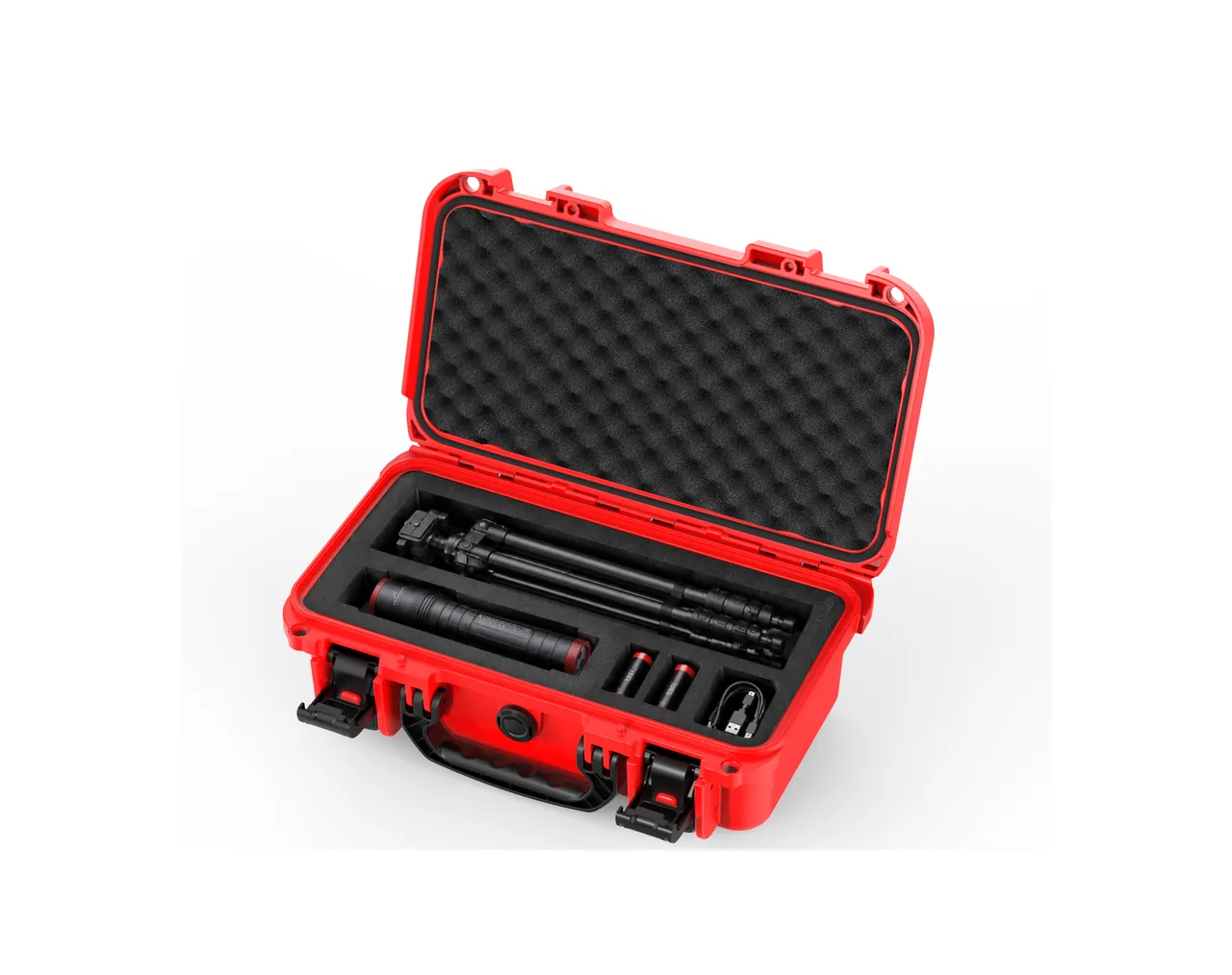
The composite principle deserves repeating: structure carries the load and foam facing provides the cushion. Pure foam cannot carry the weight of a heavy roller, and pure hard support loses all cushioning. The custom insert process is described in the note on the custom EVA foam insert process.
7. Environmental Control: Moisture, Dust, and Static
Film equipment parts face three environmental risks: humidity, dust, and static.
7.1 Humidity
| Measure | Function | Usage point | Common error |
|---|---|---|---|
| --- | --- | --- | --- |
| Desiccant | Adsorbs internal moisture | Dose by net volume and fix in place | Left loose and striking parts; quantity guessed |
| Humidity indicator card | Makes humidity readable | Fixed where it is seen on opening | Not used, leaving judgement to feel |
| Vapour-phase inhibitor | Reaches dead corners an oil film cannot | Volume should be enclosed; near but not touching | Insufficient quantity; poorly enclosed |
| Pressure equalisation valve | Balances internal and external pressure | Specified for air freight or high altitude | Mistaken for a drying device |
To state it again clearly: a pressure equalisation valve balances pressure, not humidity, and its air flow is far too small to replace desiccant. The principle is described in the note on pressure equalisation valves for protective cases. Also, after moving from a cold environment into a warm shop, allow the closed case to equalise to ambient temperature before opening to avoid condensation on cold surfaces. This matters especially for die heads because of their large thermal mass.
7.2 Dust
Dust entering a die lip gap, a flow channel, or a roller surface causes quality problems. Three controls apply: the case needs a sufficient dust protection rating, IP65 minimum and IP67 for sea freight or outdoor handling; parts must be cleaned before packing; and the case should not be left open for long periods in a dusty area.
7.3 Static
In dry environments, film equipment parts, especially electrical items and film-protected roller surfaces, accumulate static charge that attracts dust and can damage sensitive electronics. Options include antistatic insert materials, an internal grounding or shielding design, and antistatic packaging bags where needed. The relevant approach is described in ESD shielding design for protective cases and in waterproof cases and IP ratings.
8. Protecting Thin-Wall Components: Air Rings, Bubble Stabilisers, and Collapsing Frames
Blown-film lines also carry a group of easily overlooked parts: air rings, bubble stabilisers, collapsing frames, and guide roller brackets. Their shared characteristics are thin walls, large size, low stiffness, and easy distortion.
| Component | Structural character | Main failure mode | Protection point |
|---|---|---|---|
| --- | --- | --- | --- |
| Internal cooling air ring | Annular thin-wall part with a precision gap | Gap distortion, impact damage | Annular soft support, no compression |
| External air ring | Large diameter, thinner wall | Ovalisation, impact damage | Multi-point support, no stacking |
| Bubble stabiliser | Thin-wall cylinder or frame | Distortion, impact damage | Internal support ring, external soft cover |
| Collapsing frame | Large thin plate | Bending, scoring | Store flat with full-area support, never lean |
| Guide roller bracket | Welded frame | Weld distortion, impact damage | Structural compartment, no compression |
The protection logic for these parts differs from die heads and rollers. The key issue is not surface precision but overall shape retention, so the core measures are full-area support, no unsupported spans, and no stacking. Collapsing frames deserve particular attention: a large thin plate leaning against a wall or a case wall will slowly bend under its own weight, and that bending is usually irreversible. The correct practice is to store it flat with full-area support, or use a dedicated upright rack that holds the plate vertically with load distributed across its whole area.
9. Standards and Verification: IEC 60529, GB/T 4857, ISTA, and ISO 4406
9.1 Standards That Can Be Cited
| Standard | Purpose | Application in a film equipment parts case |
|---|---|---|
| --- | --- | --- |
| IEC 60529 and GB/T 4208 | Enclosure ingress protection | Establishing IP65 and IP67 dust and water capability |
| GB/T 4857 series | Fundamental transport packaging tests | Drop, stacking, vibration, and impact methods and criteria |
| ISTA procedures | Distribution cycle simulation | Combined sequences simulating cumulative logistics damage |
| ASTM D4169 | Distribution cycle simulation | An alternative verification route common on export orders |
| MIL-STD-810H | Environmental test methods | Temperature, humidity, and vibration methods, cited as method reference only and implying no military certification |
| UL94 | Material flame retardancy classification | Case material requirements for storage near electrical rooms |
| ISO 4406 | Hydraulic and thermal oil cleanliness | Cleanliness targets where hydraulic or thermal oil parts are involved |
The citation of MIL-STD-810H must be strictly worded: a technical agreement should state that high-temperature, low-temperature, damp-heat, and vibration tests may reference the relevant MIL-STD-810H methods, and must not claim compliance with a military standard or imply any military certification.
9.2 Recommended Verification Items and Criteria
| Verification item | Method basis | Recommended criteria |
|---|---|---|
| --- | --- | --- |
| Drop test | GB/T 4857.5 | No case cracking, latches functional, part displacement 2 mm or less, no new damage to lips or roller surfaces |
| Stacking test | GB/T 4857.3 | After the design height and duration, no permanent case distortion, sealing intact |
| Vibration test | GB/T 4857.7 or ISTA | No insert collapse, no roller displacement, no abnormal wear marks |
| Dust and water ingress | IEC 60529 and GB/T 4208 | The agreed IP rating achieved, no visible water or dust inside on opening |
| Damp heat test | Referencing MIL-STD-810H | No corrosion on flow channels or journals after testing, in combination with the rust prevention system |
| Material flame retardancy | UL94 | The agreed classification achieved, with material evidence |
Practical application notes are available in how GB/T 4857 transport packaging testing applies to protective cases, ISTA transport testing procedures, and ASTM D4169 distribution cycle testing.
10. Selection Process and Common Misconceptions
10.1 Seven-Step Selection Process
- Build the parts list. Die heads with lip specifications, spiral mandrels, heater bands, thermocouples, rollers by surface type and whether a journal exists, air rings, bubble stabilisers, and collapsing frames.
- Mark the precision sensitivity points. Lip gap and flow channels are first-class; roller surfaces and journals are first-class; the overall shape of thin-wall parts is first-class.
- Map the transit route. In-plant specification changes, domestic road, sea freight, air freight, or long-term storage. This determines the IP rating and whether a pressure equalisation valve is needed.
- Determine the support scheme. Prefer shaft-end support for rollers, falling back to conforming half-round cradles where no journal exists, full base support for die heads, and full-area support for thin-wall parts.
- Set the case envelope. Length from the longest roller plus cushioning at both ends, base reinforced with ribs according to total weight, and mid-length reinforcement rings plus castors and a telescopic handle for very long cases.
- Define environmental control. The rust prevention system, desiccant quantity, humidity indicator card, and static control measures.
- Write it into the technical agreement. Case material and specification, insert structure drawings, verification items and criteria, how reports are supplied, sampling ratio, and acceptance method. AQL sampling logic is a reasonable reference, as described in custom case acceptance and AQL.
If roller and die head specifications are stable and volumes are large, custom molded inserts and dedicated support seats pay off best, and the economics are discussed in the analysis of custom case mold cost. Supplier capability is assessed in how to choose a case OEM factory. Where specifications change frequently, start with a modular adjustable support system combined with standardised soft facings and rust prevention kits.
10.2 Common Misconceptions
- Misconception one: two wooden battens under a roller are good enough. Line contact leaves permanent compression marks on rubber-covered rollers, which become periodic film streaks after restart.
- Misconception two: stacking die heads saves space. Stacking applies sustained pressure to lips or flange faces and is the most overlooked source of static damage.
- Misconception three: thicker, softer cushioning is always better. Cushioning that is too soft lets a heavy roller migrate and strike repeatedly, which is worse than structure carrying the load with moderate cushioning.
- Misconception four: standing a roller upright saves floor space. A long roller standing upright has a high centre of gravity and can contact the case wall, which is riskier than horizontal storage.
- Misconception five: only the case's water resistance matters, not internal humidity. Parts packed wet, or condensation from temperature differentials, will corrode just the same. Desiccant and a humidity indicator card are required.
- Misconception six: leaning collapsing frames and air rings against the case wall. Large thin-wall parts bend slowly under their own weight, and that bending is usually irreversible.
- Misconception seven: tucking small items into gaps. Heater bands, thermocouples, and bolts become impact sources in transit and need their own compartments.
- Misconception eight: using a case straight out of the box without sampling. Insert fit, cradle height consistency, and gasket condition all require inspection.
11. Incoming Inspection and Routine Maintenance Checklist
11.1 Incoming Inspection
- Case body. No cracks or sink marks, ribs and lifting points intact, forklift pockets usable.
- Latches and hinges. Smooth operation, no play when closed. How to judge them is described in case hinges, latches, and seals.
- Seal gasket. Continuous, no joint misalignment, no scoring, even compression mark when closed.
- Die head cavity. Conforms to the die head base; lip cap correctly sized and made of soft material.
- Roller cradles. Half-round conforming, matched in height and collinear, with the roller touching every cradle simultaneously.
- Axial restraint. Clearance of 1 to 2 mm, pressing on journals or end faces rather than roller surfaces.
- Shaft sleeves and roller facings. Full-length coverage, non-shedding material.
- Environmental items. Desiccant, humidity indicator card, vapour-phase inhibitor, and static control measures in place.
- Documentation. Packing list, material statement, ingress protection and flame retardancy evidence, and required test reports.
11.2 Routine Maintenance
- Clean the case interior and insert surfaces after each use, leaving no oil or debris. Cleaning methods are described in cleaning a protective case correctly.
- Inspect the gasket periodically, apply a small amount of silicone grease, and replace it once aged.
- Replace or regenerate desiccant on colour change, shortening the interval during humid seasons.
- Replace roller facings and lip caps immediately once damaged, so they do not become scoring sources themselves.
- Replace inserts immediately on collapse, tearing, or debris shedding.
- Shake-test the closed case after every loading to confirm there is no sense of internal movement.
- Avoid outdoor storage for cases in long-term storage. Factors affecting case and gasket life are discussed in protective case service life.
Frequently Asked Questions
Q: Why does a blown-film die head so easily lose lip gap tolerance in transport?
A: Two forces are responsible. The first is localised plastic deformation from impact, typically when a lip edge strikes a hard object during lifting or when the head shifts inside the case and hits a wall. The second is more subtle: creep from sustained compression, typically when a head lies on an uneven surface or carries other spare parts and the closing pressure of the lid on top. Rubber or foam looks soft, but sustained pressure causes the material near the lip to yield slowly, eventually producing irreversible distortion. Both damage modes show up as a lip gap that is no longer uniform, and after restart the film shows transverse thickness deviation or thick and thin bands. Correcting either requires disassembly, readjustment, or regrinding. Protection centres on fitting an annular soft cap over the lip end face, never stacking die heads, never placing the lip face down under load, and replacing point support with full base support.
Q: How should a roller be supported in a case to protect the surface and prevent axial movement?
A: Split the answer by whether a usable journal exists. If the roller has usable journals, the ideal arrangement supports the roller at those journals, with bearing-seat style supports at both ends of the case so the roller surface carries no load at all, and a mid-span cradle to prevent sagging. The surface then contacts nothing along its whole length and needs only a dust sleeve, which minimises precision risk. If no usable journal exists, use conforming half-round cradle blocks so that contact becomes an area rather than a line, and make sure the blocks are matched in height, collinear, and tangent along the full length. To prevent axial movement, fit restraint blocks at both ends with 1 to 2 mm clearance. They must press on a journal or an end face and never on the roller surface. For long and heavy rollers, clamp-type structures are recommended because they limit both rolling and axial travel. Shake-test the closed case to confirm there is no sense of movement.
Q: Why should a rubber-covered roller never rest on a wooden batten or a hard cradle block?
A: Because a rubber covering develops irreversible compression marks under sustained point or line loading. A wooden batten or hard block contacts the roller along a line, so contact pressure is highly concentrated, and over time the covering is compressed continuously near that line and cannot fully recover when the load is removed. The consequence while running is significant: the mark recurs once per revolution, producing a periodic longitudinal streak or thickness variation in the film that affects winding quality and product consistency. Repairing it usually requires regrinding or re-covering the roller, at a cost far higher than the price difference between cases. The correct approach is a conforming half-round cradle that spreads load across the whole arc, or preferably shaft-end support that leaves the surface untouched. Also avoid stacking anything on top of a roller, avoid sharing a compartment with heavy parts, and protect the covering from oil contamination and ultraviolet exposure, both of which accelerate aging.
Q: How should the protection rating be chosen for a blown-film and cast-film equipment parts case?
A: Judge by the environmental boundary of transport and storage. IP65 resists dust ingress and water jets from any direction, covering in-plant specification changes, covered workshop handling, and ordinary warehousing. IP67 adds temporary immersion resistance and a higher dust-tight class, suiting sea freight, open or semi-open yards, humid high-rainfall regions, and long-term storage. Film equipment parts are high precision, have long repair lead times, and carry high unit value, and once a lip gap or roller surface is affected it persistently reduces yield. The judgement can therefore reasonably be conservative: whenever sea freight, outdoor handling, or storage beyond six months is involved, specify IP67. Read the definitions against IEC 60529 and GB/T 4208, and note that a second digit of 5 means water jets while 7 means temporary immersion. A jet rating does not cover condensation or immersion, and nightly condensation inside a sea freight container is a common occurrence. If the decision is finely balanced, choose the higher rating for high-value parts such as die heads and precision rollers, and the lower one for robust parts such as guide roller brackets, which concentrates the budget where the risk actually sits.
Q: How should die head flow channels and the spiral mandrel be protected against rust in storage?
A: Use a three-layer system and give special attention to dead corners. The first layer is surface preparation: clean, degrease, dry thoroughly, then apply a thin, even rust-preventive oil film. Thin beats thick, because a heavy film sags under gravity and traps contaminants. The second layer is vapour-phase protection: use corrosion-inhibiting film or paper inside the enclosed case so inhibitor is released continuously, focusing on flow channel dead corners, threaded holes, and ejector holes that an oil film cannot reach. Keep the material near but not in long-term direct contact with precision surfaces. The third layer is humidity control: dose desiccant by net internal volume and place a humidity indicator card, holding relative humidity below 60 percent and ideally between 40 and 55 percent. In addition, cap flow channel openings with soft plugs, confirm no residual polymer or water remains before storage, and allow the closed case to equalise in temperature before opening when moving from a cold environment into a warm shop.
Q: How should large thin-wall parts such as collapsing frames and air rings be protected?
A: The main risk for these parts is not surface precision but overall shape retention, so the protection logic differs from die heads and rollers. The core measures are full-area support, no unsupported spans, no stacking, and no leaning. A collapsing frame is a large thin plate; leaning it against a wall or a case wall lets it bend slowly under its own weight, and that bending is usually irreversible. Store it flat on full-area support, or use a dedicated upright rack that holds the plate vertically with the load distributed across the entire face. Air rings and collapsing frames should be supported at multiple points inside the case to avoid ovalisation from single-point or line contact. For thin-wall cylinders or frames such as bubble stabilisers, add an internal support ring and an external soft cover. Also consider storage near electrical rooms, where the case material can be specified to meet a UL94 flame retardancy classification with supporting material evidence.
Q: Why do die head heater bands and thermocouples fail in transport?
A: The damage comes mainly from internal fatigue rather than visible impact. Ceramic heater bands develop micro-cracks under drops and sustained vibration, and continued vibration fatigues and breaks the internal resistance wire. Mica and cast aluminium bands more often suffer shell deformation from compression, which prevents them seating properly against the die head and reduces heat transfer efficiency. The thermocouple itself is small, but its compensating lead is the real weak point: repeated sharp bending and pulling breaks the conductor internally, showing up as a jumping reading or an open-circuit alarm. Four protection points follow. Store heater bands and thermocouples in dedicated compartments with cushioning all round, never sharing with heavy parts and never stacked. Coil the leads into a generous loop and secure them with soft ties that do not contact metal edges. Fit sleeves at the connectors. And place desiccant inside the case to prevent moisture lowering insulation resistance. These small items should also have standardised label areas so they can be checked quickly during changeovers.
Q: How can a buyer verify that a parts case will actually preserve die lip and roller surface precision?
A: Verify against tests and written criteria rather than appearance and feel. Set up three layers. The first is fundamental transport packaging testing: drop, stacking, vibration, and impact per the GB/T 4857 series. The second is distribution cycle simulation: combined sequences per the relevant ISTA procedure or ASTM D4169, which is closer to a real logistics chain. The third is environmental conditioning: high temperature, low temperature, damp heat, and vibration methods referenced from MIL-STD-810H, with the clear statement that the standard is cited here only as an environmental test method reference and implies no military certification. The key is to write criteria that can be judged pass or fail, for example no case cracking after testing, latches still functional, die head and roller displacement inside the case not exceeding 2 mm, and no new scoring or compression marks on lips or roller surfaces. It also helps to record conditions, with photographs and key dimensions, before and after packing, which clarifies responsibility and builds useful data over time.
Conclusion & Related Reading
Selecting a blown-film and cast-film equipment parts case means using one box to defend two kinds of precision at once. The die head line protects the lip gap and flow channel surfaces: fit an annular soft cap over the lip, never stack or place the lip face down under load, let the head rest over its full base area in a matching cavity, plug flow channel openings, and build rust prevention from surface preparation plus vapour-phase inhibitor plus desiccant. The roller line protects the surface and dynamic balance: where a journal exists, support at the journal so the surface carries no load; where it does not, use a conforming half-round cradle to convert line contact into area contact; fit axial restraint blocks at both ends with 1 to 2 mm clearance, and make sure restraint presses only on journals or end faces. The anti-vibration line protects peak acceleration: keep cushioning at 20 to 30 mm or more around the part, enlarge contact areas to reduce contact pressure, and use softer, thicker cushioning to push the system natural frequency down. The environmental line protects against humidity and dust: dose desiccant by net volume and fix it in place, use a humidity indicator card to turn humidity into a number, remember that a pressure equalisation valve balances pressure rather than humidity, and allow a closed case to equalise in temperature before opening to avoid condensation. Verification uses pass-or-fail criteria from IEC 60529, GB/T 4857, ISTA, and UL94, with ISO 4406 cleanliness targets added where hydraulic or thermal oil parts are involved. MIL-STD-810H is cited only as an environmental test method reference and implies no military certification. JUNZHJIA, manufactured by Kexin New Materials (Guangdong) Co., Ltd., founded in 2014 in Zhongshan, Guangdong, operates an approximately 18,000 square meter factory with more than 80 production machines and over 100 employees. The protective case line covers more than 150 specifications, achieves IP67 capability, can be verified against MIL-STD-810H environmental test methods, holds ISO9001 certification, and complies with REACH and RoHS requirements. With more than 20 patents, the company provides one-stop OEM and ODM customization from product design and mold making through injection molding to inserts, liners, and logo printing, and can supply support seats and conforming half-round cradle solutions engineered to die head and roller dimensions. For volume quotations, specification requests, and customization enquiries, please use the contact page or the enquiry form on this site.
Related Reading