

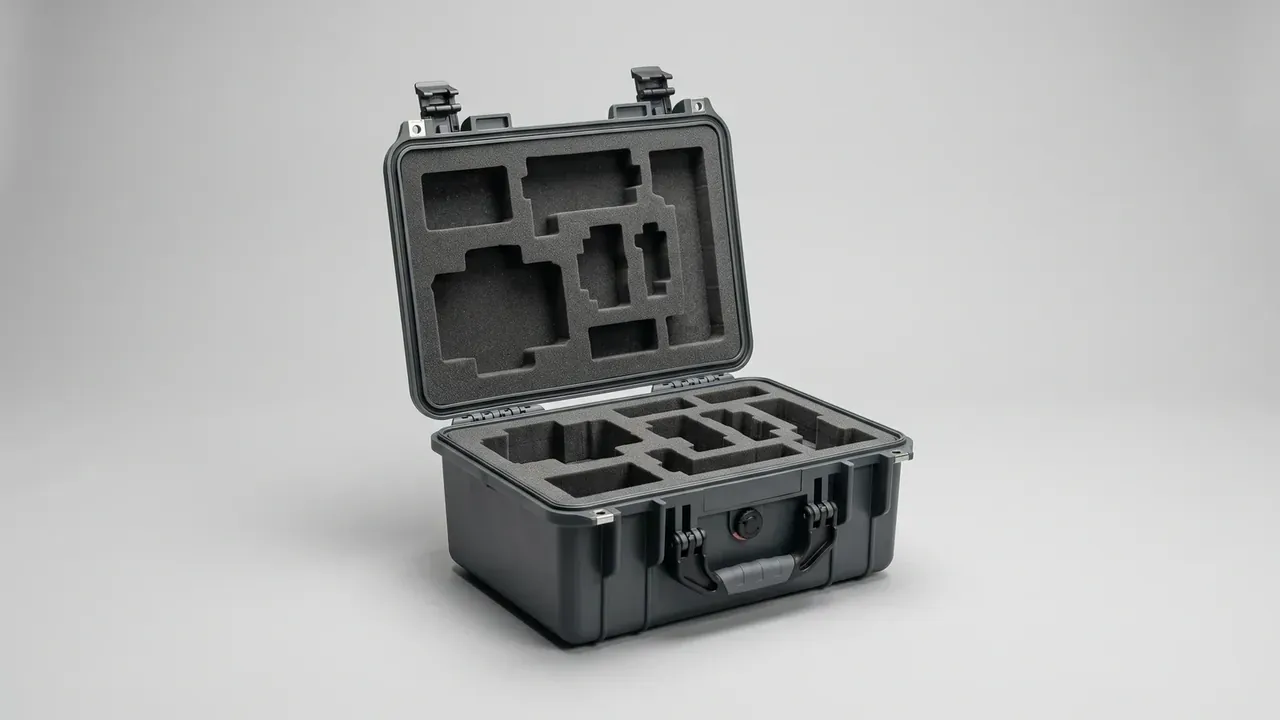
Quick answer: This Foam Insert Installation acceptance run used the contract annex, the approved sample and the drawing tolerance sheet as its basis, measured peel strength, corner gaps, compression and lid force on 50 of 320 units, and returned 27 for lifting, debonding and cut-through.
Table of contents
- Where Foam Insert Installation Acceptance Begins
- Four Tools and a Scale on the Floor
- Three Defects Behind Every Rejection
- Compression and Lid Force in Three Bands
- Sampling 320 Units Down to 50
- Rework, Concession or Return
- FAQ
1. Where Foam Insert Installation Acceptance Begins
Most arguments about Foam Insert Installation acceptance are not about instruments; they are about two parties holding different documents. Here the buyer brought an assembly drawing, the supplier a die-cutting drawing, and the two disagreed by two millimetres at the corners.
Rank the documents before measuring: acceptance annex first, signed golden sample second, tolerance sheet last, with the stricter clause winning any conflict. The drawing called for a 428 × 320 × 152 mm cavity while the die layout was cut to 426 × 318 mm, turning a 0.5 mm clearance into 1.5 mm and pushing compression up a band.
| Check item | Instrument | Pass line | Sampling |
|---|---|---|---|
| Peel strength | Digital force gauge | 1.5 N/cm, foam body fails first | 5 per batch |
| Corner gap | 0.2 mm feeler gauge | Gauge will not enter | 100% |
| Compression | Digital caliper | 12%–18% | 10 per batch |
| Lid force | Push-pull gauge | 80–120 N, latches in one motion | 3 per batch |
2. Four Tools and a Scale on the Floor
Acceptance needs no laboratory: a 0–150 mm caliper, a 0.2 mm feeler gauge, a 50 kg push-pull gauge and a 0.1 g bench scale cover it. Let the case sit at 23 °C and 50% humidity for 24 hours first.
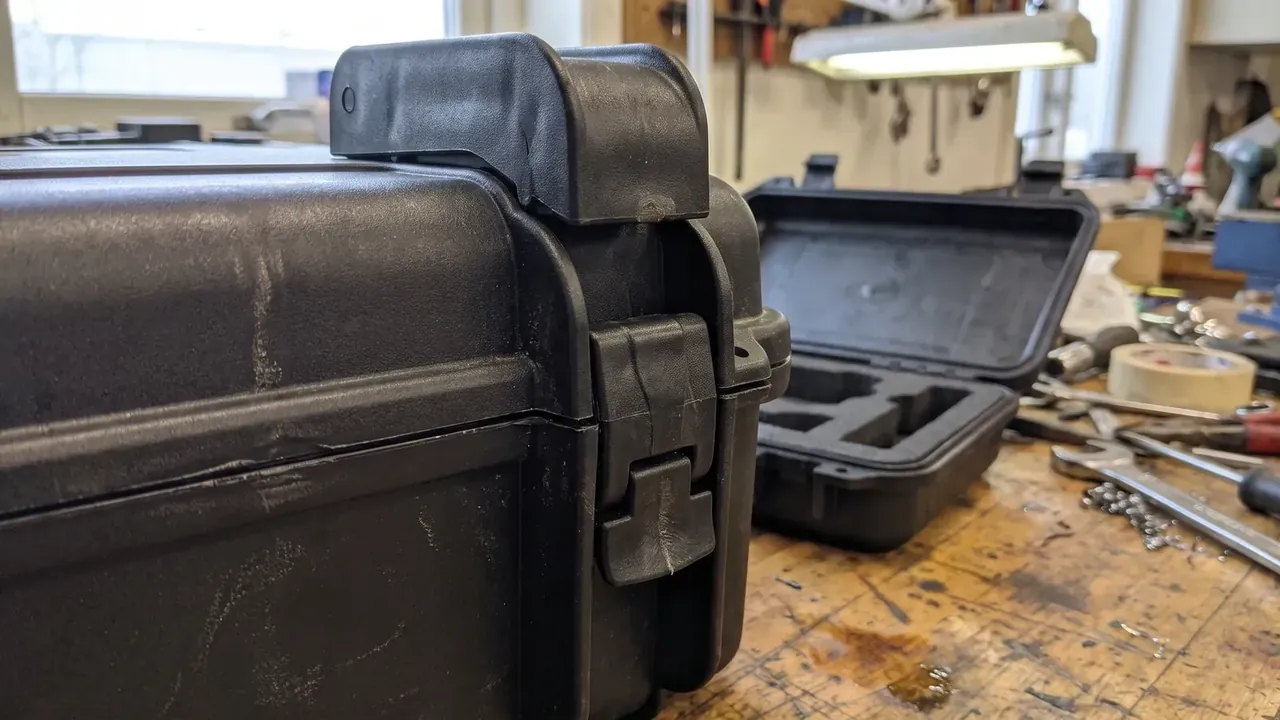
Peel strength is read on a 30 mm strip cut along the foam edge, pulled at 90 degrees and 50 mm per minute; a good result shows the foam tearing before the adhesive lets go.
Corner gaps go to the feeler gauge, compression takes two readings 60 seconds apart, and total weight within 3% of the drawing figure rules out a missing layer.
3. Three Defects Behind Every Rejection
All 27 rejects fell into three groups: 15 lifted at the corners, 8 debonded, 4 cut through. Each points to a different cause and remedy.
| Defect | What you see | Cause | Action |
|---|---|---|---|
| Corner lifting | Foam rises 1–2 mm, lid feels springy | Wall pieces laid first | Strip, reline base first |
| Debonding | Dry patches, no adhesive transfer | Open time over 40 seconds | Clean, reglue, press 30 seconds |
| Cut-through | Foam sliced by the case rib | Zero side clearance | Trim to 0.5 mm, lower compression |
Lifting tracks the corner radius: the case carries an R5 at each inner corner, so a flat cut piece piles material there and the pile pushes the lid up. Debonding is a winter problem, because at 12 °C the open time falls to 25 seconds and the starting point skins over before a perimeter is glued. Cut-through hides best: a 0.3 mm flash line stays invisible until the rib cuts the foam.
4. Compression and Lid Force in Three Bands
Compression is not a number where more is better. A single 12%–18% window is too wide, since a light item and a heavy item land in the same band with different feel and service life.
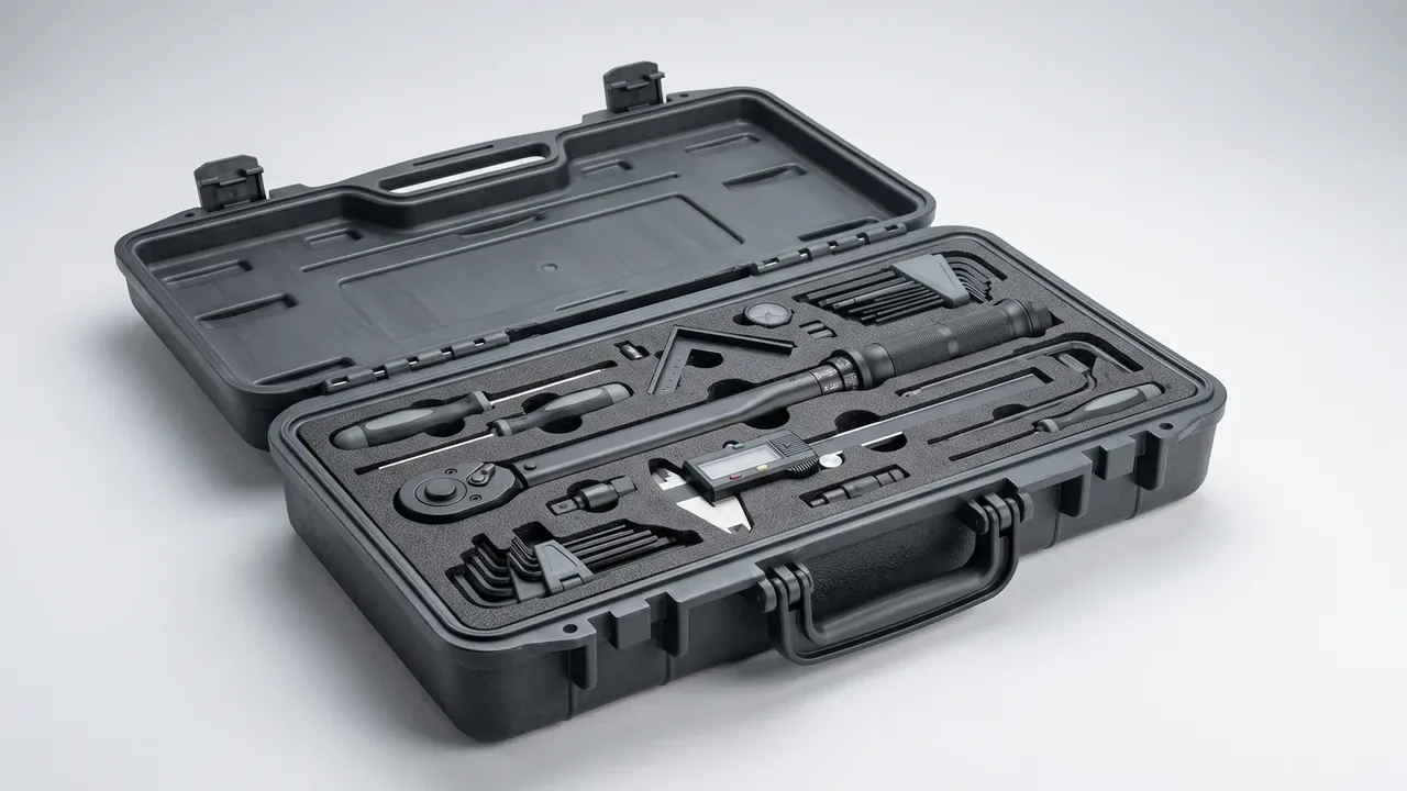
- 12%–14%: items under 5 kg, lid force 80–95 N, rebound loss under 5% after 200 cycles.
- 15%–16%: standard band, lid force 95–110 N, balanced grip and access.
- 17%–18%: items over 8 kg and rough routes, lid force 110–120 N.
Above 120 N, change the structure instead of pressing harder; the ceiling belongs to the latch. Rated for 5,000 cycles, the latches showed first wear at cycle 3,200 under 118 N and stayed far cleaner at 105 N. They also take a 48-hour neutral salt spray, so pull one pair per batch and check for white rust.
5. Sampling 320 Units Down to 50
The 320 units sat on 8 pallets; six per pallet plus the first article, the last article and the first two after any material change gave 50 units, 15.6% coverage. Sampling points sit at the four corners and centre of each pallet, where defects hide. Write the rejection rule into the annex: two failures of one type in 50 units returns the pallet, one failure triggers a doubled sample.
6. Rework, Concession or Return
Three remedies match the three causes: lifting and debonding are assembly faults, cheap to strip and reline, while cut-through is a cutting-size fault that cannot be reworked, only replaced.
Concessions need a written scope: three units had a 0.15 mm corner gap with no light leak, accepted with batch numbers on the packing list and a three-month follow-up.
Conclusion
Foam Insert Installation acceptance is settled by four decisions taken before the first measurement: which document governs, which instrument reads it, how the sample is spread, and where the rework line sits. The run returned 27 of 320 units, and once the three causes were laid out the next batch held a 4% return rate, which is how the acceptance sheet became a standing document.
This article discusses only the container (case body) side of specifications and design intent, and does not cover any handling, loading or use of the contents.
Related Reading
- How the Foam Insert Installation sequence works
- Foam Insert Installation across different scenarios
- Foam insert storage and shelf-life rules
- Custom foam insert dimensions and tolerances
- Airdrop case drop testing and acceptance
Related Products
- 8 Series — Gun Cases; Military Equipment Cases; Camera Equipment Cases; Drone Cases; Watch Cases; Knife Cases; First Aid Cases; Electronics Equipment Cases
- WL8-2812 PP Gun Case — model WL8-2812
- All protective cases and toolboxes: 7 series, 158 models