

A laser cladding system concentrates its whole value on one optical path: fibre output, collimating lens, steering mirror, focusing lens, protection slide, and finally a 2 to 6 mm spot on the workpiece surface. A single particle a few microns across sitting on any lens in that chain becomes a local absorption hotspot; the coating burns through within tens of hours, and what follows is spot distortion and a dilution rate that no longer follows the recipe. The second critical branch is the powder train, where the feeder metering element, the powder lines and the coaxial nozzle together decide where the powder lands and how densely. And the outermost ceramic ring on a coaxial nozzle is frequently the part most easily chipped and least easily noticed.
JUNZHIJIA's protection principle for laser cladding hardware is that optics are packed against a dual budget of cleanliness class and exposure time, while mechanical parts are fixed against a dual budget of metering clearance and coaxiality datum — and the two families must be physically separated rather than sharing one cavity. Where does the dust on an optical path come from? Some of it is ambient, but most of it is generated by the packing itself: ordinary bubble wrap, ordinary pearl foam debris and carton fibre all enter the lens mount the moment the case opens. Dust control therefore is not about covering the optics; it is about stepping cleanliness down progressively from the inside out.
Table of Contents
- Cleanliness Grading and Exposure-Time Control for the Cladding Head Lens Stack
- Coaxial Nozzle Ceramic Rings and Copper Tips: Clearance Features at Impact-Prone Zones
- Separate Cells for Protection Lenses and Collimating Optics: Dust Control Along the Whole Chain
- Preserving Powder Feeder Metering Clearances and Locking the Shaft Train
- Anti-Blocking Seals for Powder Lines and Carrier-Gas Fittings
- Matched Numbering for Powder Splitters and Nozzle Seats
- Dual Static-Dissipative and Dust-Tight Requirements for Optical Packing
- Residual Water Drain-Down for Water-Cooled Mirror Mounts and Cooling Circuits
- Protecting the Mounting Face Between the Cladding Head and the Robot Adapter Flange
- Clean Compartmentation for Powder Recovery Tanks and Extraction Modules
- Verifying Optical Path Coaxiality Through Vibration and Shock Testing
- Three-Step Alignment Check and Acceptance Criteria at Site Reassembly
- Frequently Asked Questions FAQ
- Conclusion and Related Reading
Cleanliness Grading and Exposure-Time Control for the Cladding Head Lens Stack
A cladding head lens stack normally carries a collimating lens, a steering mirror and a focusing lens, with beam splitters and beam-shaping elements added on high-power models. Substrates are fused silica or optical glass, and the coating is a multilayer dielectric film only microns thick. A 5 micron particle resting on that coating behaves like a strong absorber at the edge of the spot; above one kilowatt of laser power it will arc within minutes.
Cleanliness grading has to land on two numbers. Assembly takes place in an ISO Class 7 environment to ISO 14644-1, meaning no more than 352,000 particles at 0.5 microns and above per cubic metre. Packing can relax to ISO Class 8, but the environment inside the lens bag itself must be one grade tighter than the room. Exposure time is quantified the same way: from the moment a lens leaves its barrier bag to the moment it is pressed into its mount and the retaining ring is fitted, the total should stay under 15 minutes. If the lens has to be cleaned midway, the clock restarts.
Structurally, the lens stack should travel in its as-built state, meaning lenses already seated in their mounts with end caps fitted. Shipping loose components pushes the pressing operation into a non-cleanroom environment on site, which carries far more risk than the transport itself.
| Optical element | Substrate and coating | Cleanliness | Packing method |
|---|---|---|---|
| --- | --- | --- | --- |
| Collimating lens | Fused silica, multilayer dielectric | ISO Class 6 in bag | Rigid lens box, air-cell isolation |
| Focusing lens | Fused silica, high-reflectance film | ISO Class 6 in bag | Rigid lens box, axial retaining ring |
| Steering mirror | Copper or gold-coated silica | ISO Class 7 in bag | Face-down on floating cradle |
| Protection lens | Silica, anti-reflective film | ISO Class 7 in bag | Slide-type box, faces touch nothing |
| Fibre output end | Silica end cap, metal housing | ISO Class 6 in bag | End-cap boot, separate cell |
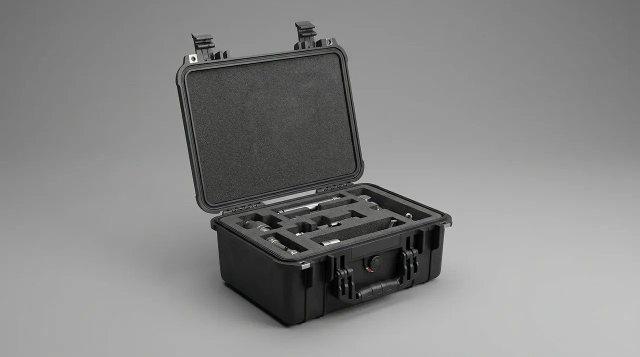
The dust-control chain mirrors the coating process upstream of it, because the transfer from coater to lens mount is where contamination is most easily introduced; the flow-control method in optical lens coating equipment cases covers that handover in full, while static-dissipative protective cases explains how to pick a surface resistance band.
Coaxial Nozzle Ceramic Rings and Copper Tips: Clearance Features at Impact-Prone Zones
The coaxial powder nozzle is the cladding head's actual pen tip. A typical build stacks an inner copper powder tip, an outer ceramic thermal ring, a gas-distribution ring and a nozzle seat. The ceramic ring wall is only 2 to 4 mm thick, has low flexural strength and produces a sharp fracture edge. Chipping a corner does not cause immediate failure, but it does unbalance the powder-gas flow field, which shows up as a cladding bead collapsing on one side and a sharp drop in powder utilisation.
Coaxiality matters more still. The nozzle centre must align with the laser axis to within 0.1 mm, and that accuracy depends entirely on the taper or shoulder fit between the nozzle seat and the cladding head body. If the nozzle stays fitted during transport, any side load passes straight through the ceramic ring into the fitting surfaces. If it is removed and packed separately, the fitting surfaces themselves must be protected.
The workable rule is therefore: nozzle off, protective cover on the fitting surfaces, nozzle in its own cell. The nozzle cradle uses an annular EPE seat whose bore is 1 to 2 mm larger than the ceramic ring outside diameter, so the load path lands on the metal body and the ceramic ring floats clear throughout the journey. Tip-up or tip-down both work, but the powder channels must point upward so residual powder cannot migrate down into the interior.
| Zone | Material | Dominant failure mode | Clearance and protection |
|---|---|---|---|
| --- | --- | --- | --- |
| Ceramic thermal ring | Alumina or zirconia ceramic | Chipping, through-cracking | Annular seat bears load, ring floats |
| Copper powder tip | Copper or copper alloy | Tip distortion, channel blockage | Boot plus sealing plug |
| Gas distribution ring | Thin-wall stainless | Distortion unbalancing gas flow | Separate cell, no wall loading |
| Nozzle seat taper | Precision stainless | Scoring that shifts coaxiality | Cover plate plus 3 mm soft pad |
| Coaxiality datum pin | Cemented carbide | Corner fracture | Own cell, static-dissipative bag |
One detail that sites notice but drawings often miss is powder-channel orientation. Coaxial channels typically converge at 15 to 30 degrees, and if the channels point downward during transport, any powder left inside them settles by gravity at the convergence point and forms a plug. On first powder-on after arrival, that plug ejects as a lump, contaminating the cladding bead or blocking a channel outright. The nozzle should therefore be fixed with channels up and the outlet fitted with a protective plug that both keeps dust out and absorbs impact. The taper surfaces on nozzle and seat must each be capped once separated, and the two must never be stacked touching each other; a single transport cycle is enough to make the coaxiality datum meaningless if they are.
Separate Cells for Protection Lenses and Collimating Optics: Dust Control Along the Whole Chain
The protection slide is the most frequently replaced part on a cladding head and one of the easiest to overlook in transit. A slide assembly combines the slide body, the protection lens, a retaining ring and an O-ring, and seals against the head body on an O-ring and a flat face. If the slide is not locked before shipment it travels freely inside the case, the lens strikes the head wall repeatedly, and the edge eventually chips.
The compartment rule is one part per cell with no lens face touching anything. Inside the lens box, the optic is held by an axial retaining ring against a radial clearance, with ring torque between 0.3 and 0.6 N·m; too much introduces assembly stress, too little lets the optic migrate. Line the box walls with 2 mm silicon-free EPE and the lid with 1 mm static-dissipative foam. Boxes are never stacked; each drops into its own recess.
Chain-wide dust control also covers O-rings and retaining clips. These small items go into their own bags labelled with size and quantity, and the shipping documents carry a matching list. In practice the most common site complaint is not a broken lens but a missing O-ring or a clip that sprang away during unpacking, which stops the whole reassembly.
Preserving Powder Feeder Metering Clearances and Locking the Shaft Train
The heart of a powder feeder is its metering mechanism. Disc-and-scraper feeders control the powder layer thickness through the gap between scraper and disc; screw feeders control delivery through the gap between screw and sleeve. Both gaps typically sit between 0.05 and 0.20 mm. Feed accuracy is quoted at plus or minus 1 to 2 percent, and a 0.05 mm shift in clearance is enough to move the actual feed rate 5 percent or more away from setpoint.
Two things need managing in transit: clearance retention and shaft locking. Clearance retention comes from radial restraint, meaning three rigid support points around the metering element's outside diameter, each with 3 mm EVA between support and housing. Shaft locking comes from axial stops that hold the shaft or screw at its design position so end-face scoring cannot occur. The stops must be countersunk-bolted into the base load beams rather than relying on foam compression.
There is also the hopper. No powder should remain inside it. Residual powder compacts under vibration and cakes, and the symptom on arrival is erratic or interrupted flow. Empty the hopper, blow down the interior walls, then close the gate between hopper and metering mechanism fully and secure it with a tie.
| Feeder type | Critical clearance | Allowable axial shift | Securing method | Extra requirement |
|---|---|---|---|---|
| --- | --- | --- | --- | --- |
| Disc and scraper | 0.05-0.15 mm | 0.05 mm or less | Three-point radial plus axial stop | Hopper emptied |
| Screw | 0.08-0.20 mm | 0.08 mm or less | Stops at both bearing ends | Sleeve end-face protection |
| Drum | 0.10-0.20 mm | 0.10 mm or less | Own compartment plus band | Grooves free of powder |
| Fluidised carrier-gas | Contactless | Not applicable | Whole-unit fixation, gas ports capped | Fluidising plate kept dry |
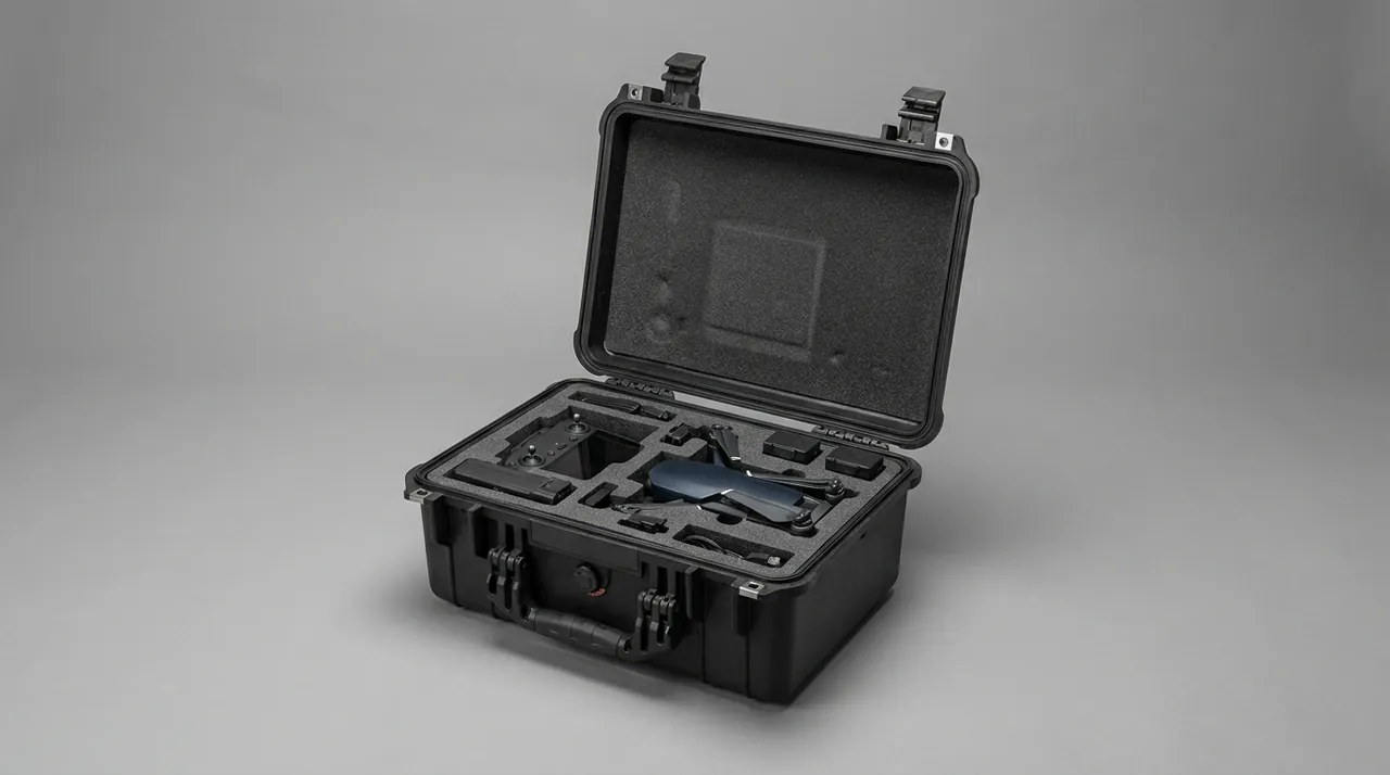
Feeders often ship separately from the laser source, and the source-side precautions are set out in fibre laser source cases.
Anti-Blocking Seals for Powder Lines and Carrier-Gas Fittings
Powder lines are typically only 3 to 6 mm in bore, and wall roughness directly affects delivery stability. Two problems dominate in transit: residual powder caking at elbows, and port deformation under load reducing flow.
Handle it in three stages. Before fitting, blow the line through with dry compressed air, rinse with anhydrous ethanol, then dry and confirm no dust remains inside. When coiling, keep the bend radius at ten times the outside diameter or more, and cap both ends with flanged plastic plugs whose exposed height is at least 5 mm so a technician can grip them. In the case, the line goes into its own channel and is never crossed by heavy parts.
Carrier-gas fittings are the other weak point. A ferrule fitting deforms permanently under side load, and a quick-connect loses grip on its locking pawls; either produces a gas leak that shows up as unstable powder flow. Fitting caps need to resist a 20 N side load without coming off and should carry grip ribs on the inner wall. All plugs and caps go into a single bag with a checklist so the site can reconcile them against the manifest.
Matched Numbering for Powder Splitters and Nozzle Seats
A multi-channel powder splitter, commonly two, four or six ways, divides one carrier-gas stream into several feeds for the nozzle channels. The channels are flow-matched at the factory, which means splitter and nozzle seat are a matched pair. Mix components from different machines during transport and one channel will overfeed while another starves — a deviation that can take a long time to diagnose in the field.
The fix is to build the numbering into the liner. Each splitter outlet gets a numbered recess, each nozzle channel gets a numbered recess, and the two sets sit adjacent in the case under the same number. A pairing table on the inside of the lid lists splitter serial number, nozzle seat serial number and channel mapping.
Implement the numbers as 0.5 mm deep laser engraving in the EVA liner, 8 to 10 mm character height, filled with contrasting colour so it stays legible under inspection lights rather than being misread. For projects shipping several machines at once, group the numbered recesses by machine and separate the groups by colour.
Numbering needs a paper trail as well. Include a ledger in the document pocket inside the lid: machine serial number, splitter serial number, nozzle seat serial number, channel mapping table and a per-recess item and quantity list. Count against the ledger before taking anything out, and if the ledger and the physical items disagree, stop reassembly and contact the supplier instead of improvising. On a line commissioning several cladding machines at once, this rule routinely saves a full day of troubleshooting.
Dual Static-Dissipative and Dust-Tight Requirements for Optical Packing
Optical coatings are also sensitive to electrostatic discharge. A discharge across a dielectric film raises local temperature by hundreds of degrees, which is enough to leave an irreversible pinhole. Optical packing therefore has to satisfy static dissipation and dust exclusion at the same time.
For materials, the inner layer is a static-dissipative PE bag with surface resistance between 10⁶ and 10⁹ ohms, and the outer layer an aluminium-foil laminate barrier bag. Avoid ordinary PE bags, which insulate and accumulate charge, and avoid black conductive bags, whose resistance is low enough to produce a discharge current on contact. Seal the bag by heat rather than with a tie, because a tie concentrates stress inside the bag and presses on the optical face.
On dust, purge each lens box with nitrogen before it goes into the barrier bag so the particle count inside the box is as low as possible. Where coating life is especially critical, a cleanroom wipe can serve as both cushion and particle trap inside the box, but it must be a silicon-free, low-outgassing grade and must never touch the coated face.
| Packing layer | Material | Surface resistance | Function | Prohibited practice |
|---|---|---|---|---|
| --- | --- | --- | --- | --- |
| Inner | Static-dissipative PE bag | 10⁶-10⁹ ohms | Bleeds static charge | Using plain insulating PE |
| Cushion | Silicon-free EPE | Not applicable | Face-contact cushioning | Using siliconised release film |
| Particle trap | Low-outgassing cleanroom wipe | Not applicable | Captures free particles | Placing it against the coating |
| Outer | Aluminium-foil laminate barrier | Not applicable | Blocks light and moisture | Sealing with a tie instead of heat |
Residual Water Drain-Down for Water-Cooled Mirror Mounts and Cooling Circuits
High-power cladding heads water-cool their mirror mounts, mirror backing plates and nozzle seats. Incomplete draining before shipment causes three problems. Residual water freezes and expands during cold transport, distorting thin-walled water cavities. In humid storage the circuit walls corrode and rust particles later block narrow passages. On first water-up after arrival, residual water mixes with coolant and produces floc.
The drain process runs blow, rinse, bake, cap. Blow dry compressed air at 0.4 to 0.6 MPa through the inlet until the outlet shows no continuous water line. Rinse the circuit with anhydrous ethanol to dissolve the residual water film. Bake at 60 degrees Celsius for 2 hours. Finally fit caps on inlet and outlet and mark the flow direction. Inside the case, keep water-cooled mounts with ports facing down so any remaining liquid drains naturally, and never invert them.
For water cavities containing copper, consider filling with dry nitrogen and capping to hold slight positive pressure. This works well on long sea voyages at modest cost, but the shipping documents must state that pressure should be relieved before connecting the circuit.
Protecting the Mounting Face Between the Cladding Head and the Robot Adapter Flange
A cladding head normally mounts to the robot's sixth axis or a gantry slide through an adapter flange. Locating pin holes on that flange are typically H7, and face flatness is in the 0.02 mm band. Once a pin hole has a burr, reassembly can no longer guarantee head posture repeatability, and that error translates directly into bead position deviation.
Protect with a three-piece set: face cover plate, pin-hole plugs and bolt-hole sleeves. The cover plate is 3 mm PP located by two dowels and clamped by two bolts at 3 to 5 N·m. Pin-hole plugs are soft nylon, inserted at least 1.5 times the hole depth. Bolt-hole sleeves are PE with flared mouths for easy extraction. On unpacking, all three items return to the checklist bag and are counted one by one.
On transport attitude, the cladding head must not sit on its flange face. Use a shoulder plate that carries the head from its body with the flange face floating 10 mm or more clear. Then even a vertical impact loads the body rather than passing through the flange face into the pin holes.

The flange protection set is counted and reconciled before handover to assembly. Where cladding heads and cutting heads ship in the same consignment, follow the part-level identification practice in laser cutting machine cases so the two families of protectors are never mixed.
Clean Compartmentation for Powder Recovery Tanks and Extraction Modules
Recovery tanks, cyclone separators and filter cartridges all share one trait: metal powder remains inside them. Under vibration that powder works into threads, sealing faces and the deep folds of a filter element. On arrival it degrades recovery efficiency and creates both a dust-explosion hazard and cross-contamination risk.
Treat all three as dusty items in their own compartment, isolated from clean parts. Empty the recovery tank and blow down the interior, then close the neck with a gasket-sealed cover carrying 1 mm of cleanroom cloth on the inner face. Stand the cyclone separator cone upward so residual powder cannot collect at the throat. Seal filter cartridges in static-dissipative bags and never let them share a cavity with dusty parts.
Fire safety is the second reason for separation. Metal powders, particularly aluminium and titanium, can generate hydrogen in humid conditions, and accumulation in a sealed space creates a deflagration risk. Give the dusty compartment a small vent and state in the shipping documents that unpacking must happen in a ventilated area with no ignition sources. The same applies to laser cladding, which routinely handles nickel-based, cobalt-based and iron-based powders. Storage and transfer conditions for those powders are covered in metal powder storage cases, including humidity thresholds and inert-gas purging.
Verifying Optical Path Coaxiality Through Vibration and Shock Testing
Optical failures are often the kind where the part looks fine and is not. Passing a visual check does not mean coaxiality is still within tolerance. Once a packing design is drafted, run a loaded validation test and measure coaxiality and feed accuracy before and after, then let the numbers decide whether the packing actually works.
Base the protocol on ISTA 3A random vibration and drop. Vibration runs 1.0 g rms vertical and 0.5 g rms horizontal for 60 minutes each; drop height follows the gross weight band, with 760 mm below 20 kg. Set three acceptance criteria: optical path coaxiality shift of no more than 0.05 mm, feed rate change of no more than 3 percent at identical settings, and no fresh cracks in the nozzle ceramic ring under 10x magnification.
| Test | Standard | Parameter | Acceptance criterion |
|---|---|---|---|
| --- | --- | --- | --- |
| Random vibration | ISTA 3A / GB-T 4857.23 | 1.0 g rms and 0.5 g rms, 60 min each | Coaxiality shift 0.05 mm or less |
| Drop | ISTA 3A / GB-T 4857.5 | 460-760 mm | No fresh ceramic cracking |
| Stacking | ASTM D4169 | 1.5 times load, 48 h | Top sag 1/200 of span or less |
| Function retest | In-house | Feed rate comparison | Deviation 3 percent or less |
Three-Step Alignment Check and Acceptance Criteria at Site Reassembly
Reassembly quality after unpacking decides whether the machine starts up first time. Work through three checks, each with an explicit pass condition, and never advance past a failure.
Step one is mechanical alignment. Refit the cladding head to the adapter flange, tighten bolts in a diagonal sequence to the specified torque, and check face contact with a feeler gauge; a 0.03 mm blade must not enter. Step two is optical calibration. Fit the protection lens and focusing lens, project the beam with a red alignment laser, and measure the offset between spot centre and nozzle centre at 200 mm standoff; it must be within 0.1 mm. Also recheck nozzle-to-axis alignment with a coaxiality gauge. Step three is a test bead. Run a 100 mm bead on scrap plate and measure width, dilution and powder utilisation against the factory record. Record the visual and audible signature of the melt pool and archive the bead with an identification number; if production anomalies appear later, this baseline is the first evidence separating an equipment problem from a parameter problem.
The acceptance form should cover at least: case sealing and pressure equalisation valve status, lens appearance and cleanliness, nozzle ceramic ring integrity, feeder free rotation and feed-rate retest, cooling circuit pressure drop on water-up, adapter flange pin holes and face condition, and returned small-part counts. Anything failing is tagged and quarantined rather than released to commissioning. These compartmented cases, clean liners and numbering schemes are produced and inspected to the actual cladding head and feeder drawings by Kexin New Materials (Guangdong) Co., Ltd.
Frequently Asked Questions FAQ
Q: Can a cladding head lens stack be wrapped in ordinary bubble wrap?
A: It is not advisable. Ordinary bubble wrap ruptures under load, and the plastic debris generated by film-on-film friction lands directly on the coating; with a spot only a few millimetres across, a 5 micron plastic particle is enough to arc and burn the film at kilowatt power levels. The correct approach keeps lenses in their mounts in the as-built state, seats the mount in a rigid lens box lined with 2 mm silicon-free EPE for face-contact cushioning, and ensures the coated face touches nothing at any point. The box then goes into a static-dissipative PE bag and an aluminium-foil laminate barrier bag, heat-sealed rather than tied. Where loose shipment is unavoidable, use dedicated rigid packing with nitrogen purging and complete reassembly in an ISO Class 7 environment rather than at the machine. Finally, keep a lens log: serial number, coating batch, cleaning date and exposure minutes. That log turns an argument about a burnt coating into a straightforward comparison of numbers.
Q: A coaxial nozzle ceramic ring has a chipped corner. Can it still be used?
A: Technically it should not be returned to service. The ceramic ring straightens the powder-gas flow and provides thermal isolation; a chip breaks circumferential symmetry, which shows up as a bead collapsing on one side and a clear drop in powder utilisation, and the crack tip keeps propagating under thermal cycling until the ring fails outright. A reasonable rule is this: chips less than 10 percent of ring thickness and clear of the gas passages may be used temporarily with a written record and a shorter inspection interval, but any chip through the ring wall or near a gas port requires replacement. Inspect with 10x magnification around the full circumference, paying particular attention to the root area where the ring meets the nozzle seat, since stress concentrates there. Keep a spare ring in the commissioning kit, and photograph the ring before shipment so any change during transit is documented rather than disputed.
Q: After transport, the feeder delivers more or less powder than set. Why?
A: The most common cause is a change in metering clearance. Scraper gaps on disc feeders and screw-to-sleeve gaps on screw feeders are only 0.05 to 0.20 mm, so if axial or radial restraint was insufficient during transport the gap shifts, and a 0.05 mm change is enough to move delivery by more than 5 percent of setpoint. Next, check whether residual powder in the hopper compacted and caked, and whether powder has built up at line elbows or in the nozzle channels. Work in that order: free-rotation check and clearance measurement first, then line blow-down and a fresh calibration against a weighed sample. If the clearance is already outside the drawing tolerance, the unit goes back to the factory for adjustment. Never compensate for a clearance fault by re-tuning the drive speed, because the underlying error will drift again as soon as the powder grade or humidity changes. Finally, weigh a timed sample of powder at the nozzle outlet rather than trusting the display, since the loss-in-weight figure is only as good as the calibration behind it.
Q: What cleanliness and static-dissipative grades does optical packing need?
A: Both requirements apply simultaneously. Assembly belongs in an ISO Class 7 environment to ISO 14644-1, packing can relax to ISO Class 8, but the environment inside the individual lens bag must be one grade tighter; keep total exposure from bag opening to final pressing under 15 minutes, and restart the clock if the optic is cleaned midway. For static dissipation, the inner bag should have surface resistance between 10⁶ and 10⁹ ohms, which bleeds charge without producing a discharge current on contact. Avoid plain insulating PE bags, which accumulate charge, and avoid conductive bags whose resistance is too low to be safe against a spark. The outer layer is an aluminium-foil laminate barrier for light and moisture, heat-sealed rather than tied so no stress concentrates inside the bag. Record the bag lot number against the optic serial number so a contamination complaint can be traced back to a specific packing shift. Note also that a bag opened for a partial build and then resealed must be recorded as an opened bag, because exposure time accumulates across every opening even when the optic was never installed.
Q: Does a water-cooled mirror mount have to be drained before shipment?
A: Yes, and thoroughly. Residual water freezes and expands in cold transit, distorting thin water cavities; in prolonged humid storage it corrodes passage walls and the rust later blocks narrow channels; on first water-up it mixes with coolant and forms floc that settles in the narrowest passages. Follow blow, rinse, bake and cap. Blow dry compressed air at 0.4 to 0.6 MPa through the inlet until no continuous water line appears at the outlet. Rinse with anhydrous ethanol to dissolve the residual film. Bake at 60 degrees Celsius for two hours. Then fit caps and mark the flow direction. Inside the case, keep water-cooled mounts with ports facing down so any remaining liquid drains naturally. For cavities containing copper, dry nitrogen filling under slight positive pressure is worth the small extra cost, provided the documents tell the site to relieve pressure before connecting the circuit. Whatever method is chosen, the drain record should travel with the head so the commissioning engineer knows the circuit was dry at dispatch and can rule it out when diagnosing a flow fault.
Q: How should residual metal powder be cleaned out of the powder lines?
A: Clean in three passes. First blow through with dry compressed air, working from the delivery end back toward the inlet so debris exits at the larger bore instead of packing into elbows. Second rinse with anhydrous ethanol and dry, which dissolves fine powder and the oil film clinging to the wall. Third inspect visually, using a borescope where necessary, to confirm no powder remains at the bends. Cap both ends immediately with flanged plastic plugs, exposed at least 5 mm so a technician can pull them off without tools. In the case, coil the line into its own channel at a bend radius of at least ten times the outside diameter, and never let heavy parts cross it, because a flattened line changes delivery stability permanently. Discard any line that shows a visible flat or kink rather than trying to straighten it, because the internal bore never returns to round and the disturbance will reappear as a periodic feed fluctuation at a specific powder setting.
Q: How is coaxiality verified after the cladding head is reassembled?
A: Work through three steps. First mechanical alignment: refit the head to the adapter flange, tighten bolts diagonally to the specified torque, then check face contact with a 0.03 mm feeler gauge that must not enter; also confirm the locating pins slide in without binding, since resistance usually means a burr in the H7 hole. Second optical calibration: with protection and focusing lenses fitted, project the beam with a red alignment laser and measure the offset between spot centre and nozzle centre at 200 mm standoff, which must stay within 0.1 mm. Third, run a 100 mm test bead on scrap plate and compare width, dilution and powder utilisation against the factory record. Only when all three pass can you conclude that neither packing nor reassembly introduced error. Log all three results against the machine serial number, because a drift that appears over several shipments is far easier to spot in a table than in memory. If the coaxiality check fails, work backwards in order: recheck the flange face contact, then the locating pins, then the nozzle seat taper, and only then suspect the optics themselves.
Q: What lead time and minimum order quantity apply to a custom laser cladding case?
A: Two variables govern the schedule: how complex the insert is, and whether new tooling is unavoidable. Starting from a stock enclosure with nothing more than an EVA liner and laser-etched numbering, the interval between approved drawings and the first dispatched unit is roughly two to three weeks. A brand-new mould changes the picture entirely — allow four to six weeks for electrode work, trial shots and at least one inspection round before the cavity is signed off. Purchasing thresholds track the tooling decision as well: off-the-shelf sizes are released from about fifty units, while a newly moulded size only makes sense from two hundred upward, because that is the volume at which the amortised tool cost stops dominating. For a development-phase project, bridge with a catalogue case and a custom insert, then commit to tooling once output is frozen.
Conclusion and Related Reading
Laser cladding risk sits half in visible mechanical parts and half in invisible optical cleanliness. Lens grading, nozzle clearance support, feeder metering gaps and flange integrity decide first-time start-up. JUNZHIJIA builds liners, numbering schemes and document sets to your drawings.
Related Reading