

A fiber laser source rated between 1.5 kW and 6 kW does not distribute its value evenly across the cabinet, the power supply or the front panel. Its worth is concentrated in the resonator cavity, the gain module, the pump combiner and the QBH output assembly. Every unit is power-calibrated, beam-quality measured and burn-in tested before it leaves the factory, and a single over-limit shock, an abnormal tilt, surface condensation or a dust intrusion in transit can reset all of that calibration work, or worse, leave an irreparable burn mark on the output fiber end face.
JUNZHIJIA's protection principle is straightforward: map the failure modes first, then design cushioning and sealing per zone, and only then validate the complete case with transport testing — never buy a case first and stuff foam into it afterward. Optical equipment differs from ordinary tools in one decisive way: its damage is often invisible, irreversible and delayed. A case for a laser source therefore has one objective — to reproduce the factory state on arrival. This article walks through risk identification, shell selection, liner layering, sealing design, test validation and acceptance criteria.
Table of Contents
- 1. A Risk Profile for Fiber Laser Source Transport
- 2. What the Resonator Cavity and Gain Module Fear Most
- 3. Stress Isolation for QBH Connectors and Delivery Fibers
- 4. Cleanliness and Vibration Control for Optics and Crystal Modules
- 5. Freeze and Leak Protection for Water-Cooling Lines
- 6. Shell Material and Structural Selection
- 7. Sealing Levels and the IP65 / IP67 Criteria
- 8. Cushion Liners: The Layering Logic of EPE, EVA, IXPE and PE
- 9. Compartment Layout and Removable Divider Design
- 10. Latches, Hinges and Pressure Equalization Valves
- 11. Temperature, Humidity, Condensation and Salt Spray
- 12. Transport Testing: ISTA, GB/T 4857 and ASTM D4169
- 13. Customization: Tooling, OEM/ODM and Documentation
- Frequently Asked Questions FAQ
- Conclusion and Related Reading
1. A Risk Profile for Fiber Laser Source Transport
A fiber laser source is an integrated assembly of three systems: optical precision, electrical power and water circulation. Its transport risks differ noticeably from those of ordinary industrial equipment. The cabinet itself usually survives normal vibration without trouble, but the internal optical modules and delivery fibers are extremely sensitive to peak acceleration, resonant frequency bands and residual displacement. Engineers generally split the risk into five categories.
The first is mechanical shock, coming from forklift set-down, loading drops and in-transit collisions. Typical signatures run from 2 to 11 ms with peak accelerations of 30 to 100 g. The second is vibration fatigue on long highway routes, concentrated between 5 and 200 Hz, where sustained energy input loosens fasteners inside the resonator and alters fiber coil geometry. The third is tilt and inversion: with a high center of gravity, tilts beyond roughly 30 degrees can let coolant migrate or dislodge components. The fourth is climate — condensation, moisture, salt spray and ultraviolet aging. The fifth is contamination and static, because dust entering the optical cavity can form ablation points under high power density.
| Failure Mode | Physical Mechanism | Typical Consequence | Protection Measure |
|---|---|---|---|
| --- | --- | --- | --- |
| Cavity detuning | Shock displaces mirror mounts beyond tolerance | Power drop, beam distortion | Low-rebound EVA cradle plus three-point limiting |
| Gain fiber fracture | Tail fiber stretched or bent past limit | Unit scrapped, factory re-splicing required | Dedicated fiber channel, arc guides, limit blocks |
| QBH end-face contamination | Dust or lint on a high-power face | Burn spot, sharp transmission loss | Dust cap, non-outgassing liner, vacuum bag |
| Coolant overpressure | Freezing or sloshing pressure peaks | Quick-coupler leaks, pooled water | Drain, plug, absorbent pad |
| Seal failure | Thermal pressure differential pulls the gasket open | Dust and moisture ingress, IP rating void | Pressure valve plus controlled groove compression |
| Insulation degradation | Condensation on high-voltage terminals | Arcing on power-up, controller damage | Desiccant, humidity indicator, barrier bag |
The value of this table is that it turns a case from a container into a set of countermeasures. Each failure mode maps to a specific structural detail rather than a vague instruction to make the walls thicker and the foam deeper. When JUNZHIJIA takes on a laser source case project, the first working session with the customer is spent completing this table, translating real transport routes, handling methods and storage conditions into measurable design inputs.
2. What the Resonator Cavity and Gain Module Fear Most
The resonator is the heart of a fiber laser. It is built from a high-reflector grating, a low-reflector grating, the gain fiber and several passive components. These parts are aligned and coil-formed to micron-level tolerances at the factory, and the finished unit passes multiple rounds of power and beam-quality testing. What the resonator fears is not compression — it is being moved at all. Any force that produces relative displacement between internal parts changes the carefully calibrated coupling state.
Gain fiber is normally wound on a cooling plate, with the coil diameter chosen by the manufacturer to balance heat dissipation against bend loss. If the case enters resonance in transit, the fiber coil vibrates with it. Over time the winding layers can shift, the thermal contact area changes, and the symptom shows up as increased power drift versus temperature. In worse cases the fiber is repeatedly flexed at a poorly limited point and finally fractures during one slightly larger shock.
The engineering answer is not to clamp the resonator rigidly but to give it a controlled support environment. The common approach: cradle the entire base with medium-to-high-density EVA in the 45 to 65 kg/m³ range so contact area is large and pressure per unit area stays low; limit the sides with low-rebound PE or IXPE that permits microscopic movement but never cumulative movement; and leave 3 to 8 mm of compression allowance at the top so the lid lightly preloads the unit and eliminates free travel. The machine neither rattles nor gets pinned.
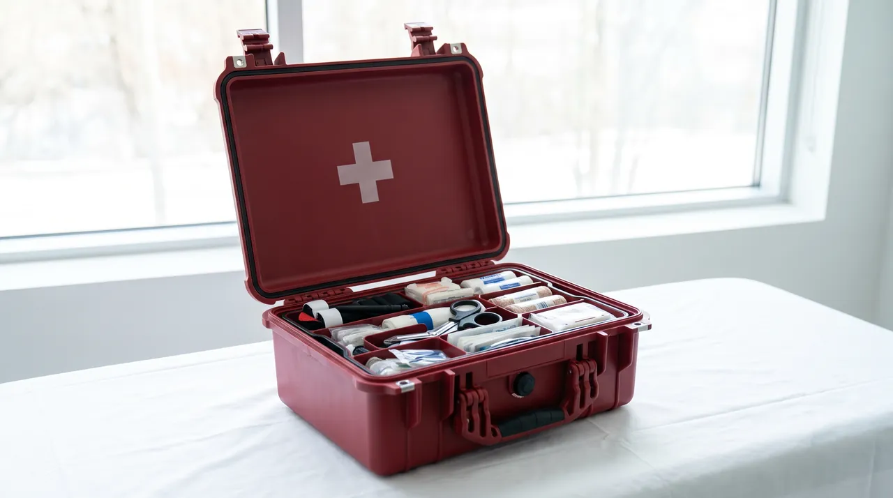
One point deserves emphasis: avoid highly resilient foam around the resonator. A high-rebound material keeps feeding energy back into the equipment during sustained vibration, forming a spring-mass coupling that can amplify response in specific frequency bands. A low-rebound, high-damping material is worth far more here than mere softness.
3. Stress Isolation for QBH Connectors and Delivery Fibers
The QBH connector is the interface between the laser source and the external optical path or process head. Its copper body carries real weight, and behind it runs a delicate delivery fiber. That fiber is one of the most fragile elements in the whole machine. Its minimum bend radius is specified by the manufacturer, typically 10 to 20 times the cladding diameter, which usually works out to a radius between 60 and 100 mm. If the fiber is pulled taut in transit, or bears against a sharp case wall, the fracture risk is very high.
The correct approach is to give the fiber a dedicated channel with generous arc guides whose radius is no smaller than the specified minimum, plus independent limit blocks that keep the fiber from sliding out of position during transport. The channel depth should slightly exceed the fiber diameter so the fiber neither floats nor gets flattened. The QBH connector body itself should be held in a dedicated contoured pocket or a nylon clamp so its own weight never becomes a force pulling on the fiber.
| Fiber or Cable Type | Typical Minimum Bend Radius | Recommended Channel Arc | Retention Method |
|---|---|---|---|
| --- | --- | --- | --- |
| Delivery fiber (QBH tail) | 60–100 mm | At least 1.2 times minimum | Contoured pocket plus limit block |
| Pump diode jumper | 30–50 mm | At least 1.2 times minimum | Half-round groove plus elastic clip |
| Water-cooling hose | 5 times outer diameter or more | Smooth arc, no sharp corners | Retaining clips plus anti-chafe sleeve |
| Control signal harness | 4 times outer diameter or more | Wide arc channel | Hook-and-loop tie with slack |
One frequently overlooked detail: the fiber channel must never share a route with cooling hoses or power cables. Hose vibration and cable friction transfer straight into the optical fiber through a shared channel. Physical separation is the cheapest and most direct measure available. At the same time, every tie point should retain a small amount of slack. Never pull the fiber into a straight, tensioned line, because the tighter it is bundled, the larger the peak force transmitted during a shock event.
4. Cleanliness and Vibration Control for Optics and Crystal Modules
High-power fiber lasers also contain collimating lenses, focusing lenses, isolators and gratings. The failure threshold of these components correlates strongly with surface cleanliness: a single micron-scale particle sitting on a high-power-density mirror surface is enough to create a local hot spot and progressively burn the coating. Protection of the optical modules must therefore solve three problems at once — no contact, no dirt and no moisture.
For cleanliness control, detachable optical modules should be bagged individually in non-outgassing PE or vacuum bags with silica gel desiccant inside, and their interfaces capped with cleanroom-grade covers. Liner material selection is critical here: ordinary EVA and some foamed materials release plasticizers and volatile organic compounds in a sealed environment, and these substances form a hazy film on optical surfaces. For contacting layers around the optical cavity, switch to non-outgassing PE, IXPE, or cleanroom-processed ESD foam.
For vibration control, optical modules should never be cantilever-mounted. If a module is fixed at one end and free at the other inside the case, the free end's acceleration response is amplified several times over, and that is the condition most likely to shift a mirror mount. The standard approach uses two or more support points plus limit blocks, converting the module from a cantilever into a simply supported beam.
| Cleanliness Risk | Source | Effect on the Optical Path | Control Measure |
|---|---|---|---|
| --- | --- | --- | --- |
| Particulate | Internal debris, liner shedding | Mirror hot spots, coating ablation | Clean interior, cleanroom bag, low-shed liner |
| Volatile organics | Outgassing from some foams | Surface haze, transmission loss | Non-outgassing materials, full curing first |
| Condensation | Rapid temperature change, poor sealing | Coating hydrolysis, mold growth | Desiccant, humidity card, seal verification |
| Static attraction | Friction charging in dry air | Particles drawn onto optics | ESD liner, grounded handling procedure |
Cleanliness and vibration control are two sides of one problem. Only when a module is firmly restrained will it stop generating friction debris through relative motion, and only when the interior is clean will particles be prevented from migrating, under vibration, to the most sensitive locations.
5. Freeze and Leak Protection for Water-Cooling Lines
Fiber lasers above 1 kW almost universally use water cooling, and the machine contains a reservoir, pump, manifold, quick couplers and several hoses. Water-circuit transport risk runs in two directions. First, residual water freezing at low temperature expands and can split a heat exchanger or hose outright. Second, sloshing in transit subjects couplers to cyclic lateral loads that gradually loosen them, and the escaping coolant creates a damp interior that threatens electrical insulation in turn.
The standard pre-shipment procedure is to drain or replace the coolant according to the manufacturer's instructions. If the minimum transport temperature could fall below 5 degrees Celsius, drain thoroughly and purge with dry air, or charge a specified concentration of antifreeze where the manufacturer permits. Every quick coupler should receive a dust plug, which both protects against contamination and prevents accidental loading in transit. An absorbent pad beneath the liner at the case floor will capture the small volume that might escape in an extreme case, keeping it away from other compartments.
| Ambient Temperature Range | Recommended Water-Circuit State | Additional Measures |
|---|---|---|
| --- | --- | --- |
| Above 5 °C | Coolant may remain, couplers plugged | Absorbent pad, ports facing upward |
| 0 °C to 5 °C | Drain or use low-concentration antifreeze | Desiccant plus transport temperature logger |
| -10 °C to 0 °C | Must drain and purge, or specified antifreeze | Absorbent pad, insulating liner, logger |
| Below -10 °C | Must drain and purge completely | Cold-chain transport protocol, on-arrival stabilization |
One rule matters as much as draining: do not power up immediately on arrival. A unit that traveled through a cold environment should rest in its unopened packaging at room temperature long enough for the whole machine to equilibrate, and only then be unpacked. Skipping this step is a recurring cause of condensation damage at commissioning sites.
6. Shell Material and Structural Selection
Shell material for a fiber laser source case is a four-way balance among weight, impact class, service environment and cost. Common options include polycarbonate (PC), PC/ABS blends, polypropylene (PP) and composite structures built from an aluminum frame with PC panels. Mechanical behavior differs substantially between them, and the cost of choosing badly usually appears after the first shipment.
PC offers first-tier cantilever impact strength among engineering plastics, combining toughness with impact resistance, and is well suited to a body that must survive drops. Its weaknesses are chemical resistance and UV stability, both of which depend on additives, and long outdoor exposure causes yellowing. PC/ABS blends balance cost against rigidity with good moldability, making them suitable for mid-size enclosures. PP excels in chemical resistance and weldability with low density and low cost, but its rigidity is modest and must be recovered through ribs and wall thickness. An aluminum frame with PC panels wins on dimensional stability and stacking load, which suits large, heavy laser source cases.
| Material | Density (g/cm³) | Impact Resistance | Rigidity | Chemical / Weather Resistance | Typical Application |
|---|---|---|---|---|---|
| --- | --- | --- | --- | --- | --- |
| PC | 1.20–1.22 | Excellent | Good | Moderate (additive dependent) | High-value units, drop resistance |
| PC/ABS | 1.10–1.15 | Good | Good | Moderate | Mid-size source cases, cost sensitive |
| PP | 0.90–0.91 | Fair | Fair | Excellent | Chemical environments, welded bodies |
| Aluminum frame + PC panels | Composite | Good | Excellent | Excellent | Large units, high stacking load |
| Glass-filled PP | 1.05–1.15 | Fair | Excellent | Good | High rigidity, lightweight goals |
Three structural priorities dominate the design. First, wall thickness must work together with rib placement; simply thickening walls adds weight, while intelligently positioned ribs deliver higher bending stiffness with less material. Second, the corner and edge radii should be generous to avoid stress concentration. Third, the floor support surface must form a stable interface with pallets, racks and vehicle floors. For the quantitative relationship between wall thickness and strength, see the analysis in Case Wall Thickness and Structural Strength.
7. Sealing Levels and the IP65 / IP67 Criteria
Fiber laser source cases are usually specified to IP65 or IP67. Both are defined by IEC 60529 and the equivalent GB/T 4208. IP65 means dust protection level 6 (dust tight) and water protection level 5 (protection against water jets). IP67 also means dust tight, but with water level 7, defined as temporary immersion, typically 1 meter for 30 minutes. For road transport and workshop staging, IP65 is usually sufficient. For cross-border routes, coastal transport or monsoon-season shipping where the case may encounter heavy rain or standing water, IP67 is the safer choice.
Sealing performance comes down to gasket material, cross-section geometry and compression ratio. Common gasket materials include EPDM, silicone and foamed silicone. The groove must be designed so that, once closed, compression lands between 25 and 35 percent. Insufficient compression leaks; excessive compression accelerates aging and creates permanent set. Corner treatment matters just as much. Corners are typically molded as one piece or bonded, and any joint should be kept away from the lower edge where water accumulates.
| Rating | Dust | Water | Typical Test Condition | Application |
|---|---|---|---|---|
| --- | --- | --- | --- | --- |
| IP54 | 5 | 4 | Splashing from all directions | Indoor staging |
| IP65 | 6 | 5 | 6.3 mm nozzle, 12.5 L/min jet | Road transport, workshop |
| IP66 | 6 | 6 | 12.5 mm nozzle, 100 L/min strong jet | Open-air loading |
| IP67 | 6 | 7 | 1 m immersion, 30 minutes | Coastal, storm, standing water |
For a closer look at how these ratings differ in practice, see IP65, IP66 and IP67 Differences. One caution: an IP rating describes only the enclosure's resistance to dust and water. It says nothing about shock, vibration or condensation. A case marked IP67 whose gasket is pulled open during a thermal swing loses its water resistance immediately, regardless of the label.
8. Cushion Liners: The Layering Logic of EPE, EVA, IXPE and PE
The liner is the most technically demanding part of the whole case solution. The same foam placed in different positions can produce opposite results. The sound approach is layered: the outer layer absorbs large impact energy, the middle layer distributes stress, and the inner layer provides fit and cleanliness compatibility.
EPE (expanded polyethylene) offers good resilience at low cost and suits large-area base cushioning, but its rebound behavior means it compresses progressively under sustained load, so it is poor for long-term support. EVA (ethylene-vinyl acetate) comes in adjustable densities with excellent formability; it can be die-cut or thermoformed into precise contoured pockets and works well as a locating layer. Medium-to-high-density EVA shows low compression set, making it a common choice for cradling optical modules. IXPE (irradiation cross-linked polyethylene) has fine, uniform cells with a smooth surface, ideal for the contact face. PE board is rigid and frequently used for dividers and structural skeletons.
| Material | Typical Density (kg/m³) | Rebound | Compression Set | Recommended Use |
|---|---|---|---|---|
| --- | --- | --- | --- | --- |
| EPE | 20–35 | High | Relatively large | Large-area base cushioning |
| EVA (medium) | 45–65 | Low | Small | Contoured locating, module cradles |
| EVA (high) | 70–110 | Very low | Very small | Heavy support, base plates |
| IXPE | 25–40 | Medium | Small | Contact faces, cleanroom surfaces |
| PE board | Thickness dependent | Rigid | Not applicable | Dividers, skeletons, reinforcement |
Liner design also has to consider operability — getting the unit in and out. Because optical equipment is often packed and unpacked repeatedly, an overly tight pocket makes operators pull hard, which manufactures a human-factor risk. A sound design leaves 0.5 to 2 mm of clearance per side and adds finger reliefs so the pack and unpack motion is natural. For more liner comparisons, see Internal Foam Types for Protective Cases and Cushion Liner Design and Selection.
9. Compartment Layout and Removable Divider Design
A fiber laser source shipment rarely contains only the main unit. The QBH protective cap, chiller couplers, control harness, spare gratings, calibration records and tools all travel in the same case. Mixed into one large cavity, metal parts knock against each other under vibration, tools scratch the housing and cables tangle with the delivery fiber. Compartmentalization is the most economical way to solve this.
The governing principle is isolation by risk class: the highest-risk optical interface gets its own compartment; cables get their own compartment and must be coiled on arcs; metal tools and spares get a separate compartment with barriers; paper documents get their own compartment with moisture protection. Dividers can be fixed, sliding or hook-and-loop removable. The value of removable dividers is that they let the internal volume be redrawn as the configuration changes, which suits small production runs across multiple models.
10. Latches, Hinges and Pressure Equalization Valves
These three hardware families decide whether the protection rating survives long-term use. Latches must deliver consistent clamping force so the gasket holds its design compression. Hinges must endure open-close cycles without developing play. Pressure equalization valves solve the differential pressure created by temperature change.
The role of the pressure valve is routinely underestimated. When a case moves from a hot workshop into a cold cargo hold, the air inside contracts and creates negative pressure. Atmospheric pressure then pushes the gasket inward, lifting it locally out of its groove. The case looks intact, yet it has effectively opened a path for water and dust. With a correctly sized valve fitted, the differential is continuously relieved and the gasket stays at its design compression. When selecting a valve, match crack pressure, airflow rate and water rating to the case rating. Details are covered in the Pressure Equalization Valve Selection Guide.
| Hardware | Key Specification | Common Failure | Selection Criteria |
|---|---|---|---|
| --- | --- | --- | --- |
| Latch | Clamping force, cycle life | Spring fatigue, force decay | Match material and geometry to cycle count |
| Hinge | Load capacity, play control | Axial movement, cracking | Metal pin, reinforced base |
| Pressure valve | Crack pressure, airflow | Membrane aging, blockage | Matched rating, replaceable membrane |
| Handle | Static and dynamic load | Root cracking | Integral molding or metal base plate |
11. Temperature, Humidity, Condensation and Salt Spray
Humidity control comes down to keeping relative humidity inside the case below the condensation threshold. The toolkit includes placing sufficient desiccant inside sealed cavities, sized by cavity volume, transit duration and target humidity; fitting a humidity indicator card in each monitored compartment so the receiver can judge at a glance; and using a temperature logger on any route that may see low temperatures, for after-the-fact traceability.
Condensation occurs whenever a surface temperature drops below the dew point. The two most dangerous moments are returning to a warm, humid environment and opening the case immediately, and the drop from a hot vehicle interior to a cool night. The first is solved by a written rule to stabilize before unpacking; the second by a degree of thermal insulation and a desiccant buffer.
Salt spray and UV mainly affect coastal transport and outdoor staging. Under neutral salt spray testing per GB/T 10125, metal parts should be stainless steel or plated, and hardware should be verified for the relevant duration. Plastic parts need attention to embrittlement after UV aging. See Salt Spray Corrosion Testing and UV Aging Test for Protective Cases for methodology.

12. Transport Testing: ISTA, GB/T 4857 and ASTM D4169
However elegant the liner design, without test validation it remains an assumption. Three systems dominate the industry, each with its own emphasis. ISTA simulates the distribution process for packaged products. GB/T 4857 provides the basic test methods for transport packages in China. ASTM D4169 organizes performance testing by distribution cycle and assurance level.
| Test Item | Reference Standard | Typical Parameters | Pass Criteria |
|---|---|---|---|
| --- | --- | --- | --- |
| Vibration | ISTA series, GB/T 4857.7 | Random vibration, 5–200 Hz | No displacement, no loosened fasteners |
| Drop | GB/T 4857.5 | Drop height set by weight | No shell rupture, no payload shift |
| Stacking | GB/T 4857.3 | Load by stack height and duration | No permanent deformation, no collapse |
| Shock | ASTM D4169 | Acceleration per assurance level | No functional failure |
| Sealing | IEC 60529 / GB/T 4208 | Water jet or immersion | No internal water ingress |
| Thermal cycling | GB/T 4857.2 | Defined temperature and humidity cycles | No condensation, no mold |
On the relationship between transport vibration and resonance, see Transport Vibration Testing Essentials and Vibration Resonance in Transport. For high-value fiber laser sources, run at least one instrumented, weighted shipment in the finished case after the liner is frozen, rather than testing an empty shell alone. Only with the actual unit inside does the test reflect the real mass-spring response.
13. Customization: Tooling, OEM/ODM and Documentation
Optical equipment packaging is usually custom, because external dimensions and internal cavity layouts differ from any general-purpose case. A complete customization process typically runs through requirement confirmation and protection-rating definition, transport risk table review, structure and liner design, 3D modeling and prototyping, drop and vibration validation, pilot production review, and volume delivery. Where new tooling is involved, mold review, trial shots and first-article approval are added.
| Stage | Deliverable | Customer Confirmation Point |
|---|---|---|
| --- | --- | --- |
| Requirements | Rating, dimensions, payload list | Transport route and handling methods |
| Design | 3D model, liner compartment drawing | Cavity layout and access convenience |
| Prototype | Sample case plus test report | Whether test criteria are met |
| Pilot run | First article, inspection records | Dimensional and cosmetic consistency |
| Volume delivery | Certificate, packing documents | Batch traceability information |
The documentation set typically includes a product certificate, packing list, liner layout drawing, gasket maintenance instructions, desiccant replacement interval recommendations, and transport and storage notes. Export projects also require documentation in the appropriate language. JUNZHIJIA supports custom tooling, OEM/ODM cooperation and branded identification, and provides a one-to-one liner layout proposal for each machine model.
Frequently Asked Questions FAQ
Q: Why can't a fiber laser source simply be shipped in an ordinary tool case?
A: An ordinary tool case is designed to hold and carry tools, and its liner logic is "fill it up so nothing moves." A fiber laser source instead needs a combination of zoning, limiting, cleanliness and moisture protection. A general case has no arc guide channel for the delivery fiber, so the tail fiber is easily pinned against a wall or pulled taut in transit. Its liner is often made from recycled foam that releases volatiles inside a sealed environment, forming a contamination film on high-power optics, and it rarely carries a pressure equalization valve, so a thermal swing pulls the gasket open. More importantly, optical damage is delayed rather than immediate. Nothing looks wrong at delivery, and the symptom appears weeks later as power loss or an end-face burn, by which time responsibility is almost impossible to establish. The repair itself may require returning the unit to the factory for fiber splicing and full recalibration. A dedicated case designed around documented failure modes is therefore not an accessory but part of the machine's calibration warranty.
Q: Should the resonator and gain module be clamped tight or left with clearance?
A: The correct answer is controlled support, not simple clamping and not open clearance. Cradle the base with medium-to-high-density EVA across a large area so contact pressure per unit area stays low. Limit the sides with low-rebound PE or IXPE that permits microscopic movement but never cumulative movement. Leave 3 to 8 mm of compression allowance at the top so the closed lid applies light preload and removes free travel. The unit then neither rattles inside the case nor gets pinned rigidly, which would concentrate stress at a few points. Note especially that high-rebound foam should be avoided around the resonator. Under sustained vibration it behaves like a spring and feeds energy back into the equipment, amplifying response in particular frequency bands, which is exactly the fatigue mechanism that loosens internal fasteners. A low-rebound, high-damping material is worth far more here than softness alone. If the customer's route involves repeated short shipments, re-verify the preload after a few cycles, because foam takes a compression set over time and the initial interference gradually disappears.
Q: What special handling do the QBH connector and delivery fiber need in transit?
A: First, give the fiber a dedicated channel whose arc radius is at least 1.2 times the manufacturer's specified minimum bend radius; delivery fiber minimums commonly fall between 60 and 100 mm depending on cladding diameter. Second, retain the QBH body in its own contoured pocket or a nylon clamp so its weight never becomes a force pulling on the fiber. Third, never route the fiber channel together with cooling hoses or power cables, because physical separation is the cheapest and most direct protective measure available. Fourth, leave a small amount of slack at every tie point and never pull the fiber into a straight, tensioned line, since a tighter bundle transmits a larger peak force during a shock event. Finally, fit a cleanroom-grade dust cap to the connector face and confirm before bagging that it carries no fingerprints or particles. Contamination at the end face is not a cosmetic issue; under full power it becomes a localized burn spot that destroys the connector and forces a factory repair.
Q: Does the water circuit need to be drained before shipment, and at what temperature is draining mandatory?
A: It depends on the lowest temperature the route may encounter. Above 5 degrees Celsius, coolant may remain in the circuit, but every quick coupler must be plugged and oriented upward, with an absorbent pad on the case floor to contain any seepage. Between 0 and 5 degrees Celsius, drain the circuit or charge low-concentration antifreeze, and place a transport temperature logger inside the case. Between minus 10 and 0 degrees Celsius, draining and purging are mandatory, or a manufacturer-approved antifreeze must be charged at the specified concentration. Below minus 10 degrees Celsius, the circuit must be completely drained and purged with dry air under a cold-chain protocol agreed with the carrier. Water expands by roughly nine percent when it freezes, which is more than enough to split a heat exchanger or a hose. On arrival, do not power up immediately; let the unit rest in its unopened packaging at room temperature until temperatures equalize, then unpack and inspect, because this rest period is the key safeguard against start-up condensation.
Q: If a case is rated IP67, does that guarantee no water reaches the equipment inside?
A: No, that inference does not hold. An IP rating describes the enclosure's protection under standard test conditions, and it presupposes that the gasket sits at design compression, that the groove is undamaged and that the hardware maintains correct clamping force. In real transport, thermal pressure differentials create negative or positive pressure across the gasket. Without a pressure equalization valve, atmospheric pressure can lift the gasket out of its groove, so the case looks perfectly intact while a water path has already opened. Gaskets also age under ultraviolet exposure, ozone and repeated compression, so compression set grows and clamping force decays over time. IP67 is therefore a design starting point rather than an endpoint. It must be paired with a correctly matched valve, disciplined open-and-close handling, periodic gasket inspection and replacement at the recommended interval. Only then does the rating remain meaningful across the service life of the case, and only then can a buyer rely on it in a warranty discussion.
Q: How should liner foam be chosen, and why avoid recycled foam?
A: Choose the liner in layers according to function. Large-area base cushioning can use EPE, which is resilient and inexpensive but unsuitable for long-term support because it compresses progressively. The locating layer should use medium-to-high-density EVA, which has low compression set and can be die-cut or thermoformed into accurate contoured pockets. The contact face against the equipment can use IXPE, which has fine uniform cells and a smooth surface that is less likely to shed. Recycled foam is problematic because its composition is uncontrolled; it may contain plasticizers, residual blowing agents and fine debris. Inside a sealed case these substances release slowly, and the release rate rises with temperature, eventually forming a hazy contamination film on optical surfaces or seeding hot spots where power density is high. For sensitive equipment such as fiber laser sources, contact layers should use non-outgassing, low-shed materials that have been fully cured, and the case interior should be cleaned before packing. Ask the supplier for the foam specification sheet rather than accepting a generic description, because density and formulation vary widely.
Q: Why does sealing sometimes fail after a case has been stacked in storage or transport?
A: Seal failure originates in elastic or plastic deformation of the case under stacking load. When the lid carries weight from above, it deflects slightly. If the supporting structure lacks stiffness, the gasket groove compression drifts away from its design value and can even open locally at the corners. Plastic cases also creep under long-term static load, and the deformation accumulates irreversibly over months of storage. Countermeasures include limiting stack height to the design value, using pallets to distribute load, avoiding point loads directly over the lid center, and placing the heaviest cases at the bottom of the stack. Structurally, ribs in the lid and load-bearing columns at the corners improve behavior considerably, and a composite aluminum-frame construction may be necessary where stiffness is critical. Always confirm the load rating marked on the case top before stacking, and recheck gasket compression after a long storage period, because a case that passed sealing tests when new may not hold its rating after months under continuous load.
Q: What review stages does a custom fiber laser source case normally go through?
A: A complete process has seven key stages. First, requirement confirmation covering protection rating, external dimensions, payload list and transport route. Second, a risk review in which the customer and supplier complete a failure-mode table together. Third, design, delivering a 3D model and a liner compartment drawing. Fourth, prototyping, producing a sample case and completing drop, vibration, stacking and sealing tests. Fifth, first-article approval, where the customer verifies dimensions, appearance and the test report. Sixth, pilot production review, checking batch consistency and process stability. Seventh, volume delivery with a certificate, packing list, liner layout drawing and maintenance instructions. Where new tooling is involved, mold review, trial shots and tooling first-article approval are added. This sequence keeps design intent, manufacturing capability and field reality aligned before volume tooling is cut, and it gives both sides a documented basis for accepting or rejecting each milestone. Customers should involve the actual handling and transport staff in the reviews wherever possible.
Conclusion and Related Reading
JUNZHIJIA builds fiber laser source cases around documented failure modes, from zoned liners to custom tooling. Manufactured by Kexin New Materials (Guangdong) Co., Ltd., with full OEM/ODM support.
Related Reading