

In cement grinding halls, open quarries, photovoltaic sites and desert telecom shelters, equipment usually stops working because of dust rather than a dramatic drop. Particles below 75 micrometres follow breathing airflow into the joint between lid and base, deposit a hygroscopic or conductive film on boards, scatter light on optical windows, and turn grease on guide rails and lead screws into lapping compound. The difficulty is that finer particles pass more easily through a nominally closed joint, while a tighter joint means worse opening feel and shorter seal life.
JUNZHIJIA designs dustproof cases around a single engineering principle: dust protection is not about sealing a box shut, but about establishing a quantifiable, verifiable and repeatable balance between pressure equalisation, service life and particle capture efficiency. The sections below work through that balance from damage mechanisms to the parameters and acceptance criteria that belong in a purchase specification.
Table of Contents
- What Dust Actually Does to a Protective Case
- Reading IP5X and IP6X Correctly under IEC 60529
- Dust Chamber Testing: Methods and Pass Criteria
- Sealing Interface Design: O-Rings, Lip Seals and Face Compression
- Labyrinth Geometry: Non-Contact Defense and Its Limits
- Filter Vents: Balancing Pressure Equalisation Against Particle Ingress
- Positive Pressure Dust Protection: When Active Defense Pays Off
- Sealing Face Wear: The Coupled Failure of Abrasion and Embedding
- Material Modulus and Shell Stiffness Behind Seal Durability
- Latch, Hinge and Clamp Force Distribution
- Liners and Compartments as a Second Line of Defense
- Industry Application Matrix and Selection Checklist
- Acceptance Criteria and Incoming Inspection Plan
- Frequently Asked Questions FAQ
- Conclusion and Related Reading
What Dust Actually Does to a Protective Case
Before any sealing decision, dust has to be resolved into measurable parameters: size distribution, hardness, shape, moisture content, electrostatic behaviour and airborne concentration. Cement raw meal sits around 10 to 30 micrometres and cakes once it absorbs moisture. Quarry and granite cutting dust runs 20 to 80 micrometres at roughly Mohs 7 and is the classic abrasive threat. Metal grinding spans sub-micron fume to sharp flakes of several hundred micrometres. Coal and carbon powders add conductivity and combustibility. Each demands a different response.
Once inside, dust damages equipment through six routes: abrasive wear when particles embed in the seal lip and score the mating face; electrical failure when hygroscopic dust forms an ion migration path; optical attenuation from a scattering layer on windows; rising thermal resistance as heatsink gaps fill, adding 10 to 20 °C to internal temperature rise; binding motion pairs as grease becomes lapping compound; and ignition risk from static accumulation in combustible atmospheres.
| Dust type | Median size | Dominant risk | Design response |
|---|---|---|---|
| --- | --- | --- | --- |
| Cement and lime | 10–30 µm | Caking, alkaline attack, groove clogging | High-grade seal, washable exterior, anti-caking finish |
| Quarry and rock | 20–80 µm | Severe abrasive wear | Labyrinth pre-stage, hard mating face, wiper lip |
| Metal swarf | 1–300 µm | Conductive bridging, sharp-edge penetration | Double seal, antistatic liner, magnetic baffle |
| Coal and carbon | 5–50 µm | Conductive deposit, ignition risk | Antistatic shell, ground terminal, positive pressure |
| Fibrous and salt dust | >20 µm | Clogging, hygroscopic corrosion | External shield, sealed joint, desiccant control |
Dust almost never acts alone: it superimposes on thermal cycling, humidity swings and vibration. Cycling drives the breathing airflow that pulls particles in, humidity turns an inert particle into an electrolyte, and vibration migrates deposits to the seal face. Judge dust protection not by static gap width but by how many particles can cross the joint over a full service cycle.
Reading IP5X and IP6X Correctly under IEC 60529
IEC 60529, mirrored by GB/T 4208, uses two characteristic numerals: the first covers solid ingress, the second water. Dust ratings come entirely from the first numeral, and the levels that matter are 5 and 6. Reading IP5X as half the protection of IP6X is a common purchasing error. The standard defines 5 as dust-protected, where a limited quantity may enter but must not interfere with operation or safety, and 6 as dust-tight with no ingress at all. The difference is qualitative, not quantitative.
The second confusion is mixing the numerals: the 6 in IP6X says nothing about water, just as the 7 in IPX7 says nothing about solids, and a specification reading simply IP6 is incomplete without the placeholder X. JUNZHIJIA writes the full code in every proposal to remove ambiguity.
The choice is a cost and risk trade-off. IP6X demands a continuously closed joint, a dust-tight vent element and enough shell stiffness to hold clamp force under thermal soak and stacking load, raising cost, weight and opening effort. IP5X permits harmless ingress and simplifies the design when the payload is not dust sensitive. The decisive question is where the dust lands and whether it triggers any of the six failure routes.
| Item | IP5X dust-protected | IP6X dust-tight |
|---|---|---|
| --- | --- | --- |
| Definition | Limited ingress allowed, no effect on operation or safety | No ingress |
| Test dust | Talcum powder through 75 µm sieve | Same |
| Concentration | 2 kg per cubic metre | Same |
| Duration | 8 hours | 8 hours |
| Pressure condition | Ambient, agitated cloud | Internal vacuum, differential at or below 2 kPa |
| Extraction rate | Not applicable | 40 to 60 shell volumes per hour |
| Verdict | Deposit must not affect function or safety | No visible deposit |
A rating certificate only covers the sample as submitted: a softer seal batch, lower latch torque or a coarser membrane can each drop real performance by a level. JUNZHIJIA therefore locks seal compound, hardness, compression ratio, latch count and membrane specification into the supply agreement and repeats them in incoming inspection. Further background is available in Dustproof Design for Outdoor Cases and Toolbox IP54 versus IP65 Ratings.
Dust Chamber Testing: Methods and Pass Criteria
Dust performance can only be established in a dust chamber; visual checks and water sprays are not substitutes. A chamber comprises a sealed volume, a talcum circulation system, a blower or nozzle arrangement that keeps the cloud suspended, a vacuum port and a differential gauge. The powder must pass a specified metal square-mesh sieve and its reuse count must be controlled, because repeated fracturing shifts the distribution finer and distorts severity.
The sample is assembled exactly as it will be used, with lid, latches, vent and every interface fitted, then placed in the chamber. For IP6X the interior is connected to a vacuum pump and extracted at a rate calculated from free internal volume so the shell stays below ambient; for IP5X no vacuum is drawn. The run lasts eight hours, after which the sample rests before being opened.
Pass criteria need to be operational. For IP6X the usual method is to wipe a suspect area with clean white cloth or lift a tape sample and compare it against an unused reference; a stricter variant places weighed glass slides inside and limits mass gain. For IP5X the location decides the verdict: dust on a non-functional surface that does not affect cooling or insulation can pass, while dust on a board, connector, optical window or motion pair should fail even in tiny amounts.

Four failure modes dominate chamber testing. The seal lip flips or migrates when the groove is oversized or compression too low. The vent clogs, so during the vacuum phase the shell is sucked in and the joint opens momentarily. Clamp force is insufficient and the lid lifts locally. Interfaces and cable entries were never included in the protection concept and act as a short circuit for dust. JUNZHIJIA runs two development rounds: the first exposes structural weaknesses, the second confirms the frozen design, with a closed-loop record of every change.
| Test parameter | IP5X | IP6X | Note |
|---|---|---|---|
| --- | --- | --- | --- |
| Test dust | Talcum | Talcum | Through 75 µm metal sieve, moisture controlled |
| Concentration | 2 kg/m³ | 2 kg/m³ | Referred to effective chamber volume |
| Duration | 8 h | 8 h | No opening mid-test |
| Internal pressure | Ambient | At or below 2 kPa below ambient | Monitored with a differential gauge |
| Extraction rate | — | 40–60 volumes per hour | Derived from free internal volume |
| Sample condition | Fully assembled | Fully assembled | Including vent, interfaces and latches |
| Verdict | Deposit harmless | No visible deposit | Weighing method recommended |
A usable report records sample number, seal batch, latch torque, membrane model and opening photographs; without those fields production traceability fails. Where water protection is also required the joint logic is identical although the equipment differs: see System-Level IP67 Design.
Sealing Interface Design: O-Rings, Lip Seals and Face Compression
The sealing interface is the heart of dustproof design. A reliable interface satisfies three conditions at once: contact stress high enough to block the particle path, contact width large enough to create a tortuous route, and mating roughness low enough to stop particles lodging. Low contact stress lets breathing airflow carry fines through a gap of a few microns; excessive roughness lets particles sit between asperities and prop the face into a stable leak path.
O-ring design turns on two ratios. Compression normally sits between 15 and 30 percent: below 15 percent contact stress cannot compensate for flatness error, above 30 percent compression set accelerates and opening effort climbs steeply. Groove fill is held between 70 and 90 percent so thermal expansion and compression flow have room without extruding the seal. Cases opened frequently should sit at the low end of the range and be compensated with greater contact width, for example a flat section or dual-bead profile.
Lip seals dominate in larger enclosures. Their advantage is high local contact stress at low clamp load, because contact concentrates on a narrow land, plus useful self-energising behaviour as internal pressure pushes the lip onto the face. The trade-off is sensitivity to wear and roll-over; once a hard particle cuts a notch in the lip, sealing decays quickly. In quartz and metal swarf environments JUNZHIJIA therefore specifies a twin-lip section: an outer wiper rejects coarse particles and scrubs the face, a primary lip performs the final block.
| Seal type | Compression | Contact width | Opening effort | Wear resistance | Best used for |
|---|---|---|---|---|---|
| --- | --- | --- | --- | --- | --- |
| Solid O-ring | 15–30% | 1.5–4 mm | Medium | Medium | Small cases, infrequent opening |
| Hollow extruded bulb | 20–40% | 4–10 mm | Low | Lower | Large lids, poor flatness |
| Single lip | By lip design | 0.5–2 mm | Low | Lower | Frequent access, weight sensitive |
| Twin lip wiper plus primary | 10–20% primary | 0.5–2 mm | Medium | High | Hard mineral dust, long outdoor service |
| Dual bead with buffer cavity | 15–25% each | 2–5 mm each | High | High | IP6X targets, critical payloads |
| Metal face with conductive gasket | — | Full perimeter | High | High | Combined EMC and dust-tight duty |
The mating face matters as much as the seal: injection-moulded faces should be held to Ra 0.8 to 1.6 micrometres, machined metal to Ra 0.4 to 0.8. Flatness matters more still, because deviation across a large lid is measured in millimetres and no seal can absorb that economically. Control deformation structurally through ribs and clamp distribution, then let the seal absorb only micro-irregularity. The internal target at JUNZHIJIA is less than 0.1 mm normal deflection in the groove region at nominal latch torque.
Labyrinth Geometry: Non-Contact Defense and Its Limits
A labyrinth is a dust defense that does not rely on clamp force. Its principle is not blocking but redirecting: a multi-stage folded channel turns a straight particle path into a series of turns, so particles lose energy through inertial impact, gravitational settling and flow reversal, and drop out in the cavity. Because the critical surfaces never touch, a labyrinth barely wears, outlasts any elastomer lip and adds nothing to opening effort.
Three parameters govern performance. Stage count, the number of flow reversals, is normally two to four; more stages improve capture but raise tooling cost. Channel clearance is usually 0.5 to 1.5 mm: tighter risks rubbing once the shell deflects or tolerances stack, looser degrades capture. Turn angle should be at or beyond 90 degrees so particles have a genuine inertial impact opportunity.
| Parameter | Recommended range | Effect |
|---|---|---|
| --- | --- | --- |
| Stages | 2 to 4 | More stages raise capture and tooling cost |
| Clearance | 0.5–1.5 mm | Wider gaps lower capture but tolerate deflection |
| Turn angle | 90–180 degrees | Sharper turns improve inertial impact |
| Channel length | At least 3 times clearance | Longer paths allow settling |
| Cavity volume | Six months of deposit | Insufficient volume shortens cleaning intervals |
The limits must be stated plainly. A labyrinth works well on coarse particles above roughly 50 micrometres and does almost nothing against sub-micron fume, because fine particles follow the streamlines. It also cannot resist a sustained pressure difference: a shell left at negative pressure after a high-altitude descent draws fines straight through. Its correct role is therefore as a pre-stage ahead of an elastomer seal, removing coarse particles and most of the mass flow while the lip handles fines. Used that way, lip wear drops by an order of magnitude and the assembly still reaches IP6X.
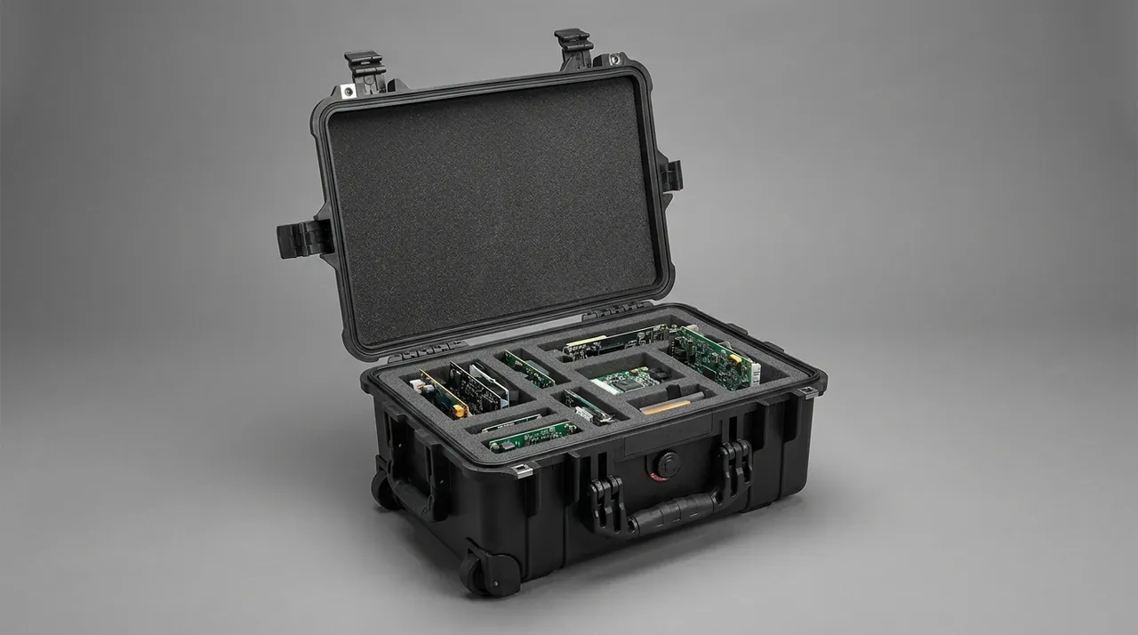
Injection-moulded labyrinth walls need adequate draft and no undercuts; rotomoulding gives generous radii but looser dimensional control, so clearances need dedicated verification. At JUNZHIJIA a labyrinth proposal must clear a tooling feasibility review and an assembly tolerance study or revert to a twin-lip seal. See Rotomolded Protective Cases and Engineering Plastics for Outdoor Cases.
Filter Vents: Balancing Pressure Equalisation Against Particle Ingress
Every sealed enclosure faces the same problem: temperature and altitude changes drive internal pressure away from ambient. A 40 litre case cycling between a 45 °C afternoon and a 5 °C night develops several kilopascals of differential, and transport to a 3000 metre site is worse. A rigid, airtight shell responds by deforming, opening the joint or refusing to open. Yet the moment a plain vent hole is drilled, dust has a direct route in.
A filter vent resolves the contradiction. Its core is an expanded PTFE microporous membrane with pores from roughly 0.1 to 5 micrometres, far below virtually all dust, combined with porosity of 70 to 90 percent so meaningful airflow passes at very low differential. Such membranes are themselves rated dust-tight, so a vent does not degrade the enclosure rating provided the membrane is intact, its housing is sealed to the shell and it has not clogged.
Selection checks four parameters. Airflow should be derived from the peak breathing flow implied by shell volume and rate of temperature change, with a two to three times margin. Protection rating matters for critical payloads: specify IP6X or better for the membrane assembly. Temperature and chemical compatibility are usually limited by the housing and bonding process rather than the PTFE. Mounting style, threaded, snap-in or weld-in, should suit maintenance access, and threaded types need their own interface seal verified.
| Symptom | Likely cause | Corrective action |
|---|---|---|
| --- | --- | --- |
| Crusted membrane, falling airflow | Dust plus humidity caking | Add pre-filter, relocate, shorten change interval |
| Dust at vent to shell joint | Unsealed thread, low torque | Add gasket, specify torque, use weld-in type |
| Membrane wetted by oil mist | Oil and dust coexisting | Add mist separator, use oleophobic membrane |
| Membrane ruptured | Impact or overpressure | Fit guard, increase vent area |
| Case still hard to open | Insufficient vent area | Increase membrane area or vent count |
Position determines service interval: choose a leeward side or underside face out of the dominant dust direction, shield any top-mounted vent, and add a replaceable coarse pre-filter. For permanently installed equipment JUNZHIJIA recommends a three-layer arrangement of vent, removable shield and pre-filter that extends membrane life from a few months to more than a year. See Pressure Equalization Valves for Protective Cases.
Positive Pressure Dust Protection: When Active Defense Pays Off
Passive sealing keeps outside dust out; positive pressure makes internal air flow outward instead. Held slightly above ambient, the pressure gradient across every gap points outwards and particles cannot travel against it. The approach is well established in cabinets and permanently installed instrument bays, and remains a costly option for portable cases.
A system comprises an air source, a filtration and drying stage, a pressure regulator with monitoring, and overpressure relief. Set point should stay modest, typically 5 to 30 mbar or about 0.5 to 3 kPa: too little cannot overcome wind gusts, too much loads the shell, accelerates seal creep and wastes air. Intake air must be filtered and dried, because an unfiltered supply turns the system into a machine for pumping dust and moisture into the case.
Air source selection follows site conditions. Fixed sites with compressed air or mains power run a small continuous pump; unpowered field points rely on dry gas cylinders or manual top-up with a check valve and pressure switch, and a well-sealed system holds pressure for weeks on one charge. JUNZHIJIA always measures leakage rate before recommending positive pressure, because if the source cannot outpace leakage the system spends its life below set point, wasting air without delivering protection.
| Dimension | Passive sealing | Active positive pressure |
|---|---|---|
| --- | --- | --- |
| Principle | Block the particle path | Reverse the flow direction |
| Initial cost | Low | High |
| Running cost | Near zero | Power or gas plus filter changes |
| Maintenance | Low | Higher, pressure and supply checks |
| Failure character | Gradual as seals wear | Sudden when supply stops |
| Portability | Good | Poor |
| Best fit | Portable and transport duty | Fixed cabinets, unattended sites |
Acceptance must include a supply-loss test: after the source is cut, the enclosure should hold pressure above the lower limit for a specified period with no ingress before pressure is fully lost. That result separates genuine positive pressure protection from brute-force high flow. For long-term field electronics JUNZHIJIA specifies positive pressure in parallel with passive sealing rather than instead of it; see Protecting Electronics in Outdoor Cases.
Sealing Face Wear: The Coupled Failure of Abrasion and Embedding
Seal face wear is the signature failure mode of dustproof cases in mineral environments, and it is distinctive because embedding and abrasion accelerate each other. A particle embedded in the elastomer becomes an abrasive tool, scoring the face on every cycle; the score lowers contact stress and admits more and larger particles. Once that loop starts, sealing falls away while the case still looks normal.
Material choice is the first lever. Silicone offers the widest temperature range and lowest compression set but only moderate tear and abrasion resistance, so sharp particles cut it. EPDM gives excellent weathering and ozone resistance at low cost but swells in mineral oil, which rules it out where oil mist and dust coexist and points to NBR or FKM. Thermoplastic elastomer moulds or co-extrudes with the shell and recycles well, but shows higher compression set at temperature. Hardness involves a real trade-off: compounds around 40 to 50 Shore A conform to rough faces but embed particles easily, while compounds near 60 to 70 Shore A resist embedding but need more clamp load for the same contact stress.
| Failure mode | Root cause | Evidence | Countermeasure |
|---|---|---|---|
| --- | --- | --- | --- |
| Abrasive scoring | Hard particles in the lip | Linear scratches, falling contact stress | Wiper lip, harder lip surface, polished face |
| Compression set | Long compression plus heat | Poor rebound, lid will not seat | Low-set compound, lower compression, rebound feature |
| Lip roll-over | Oversized groove, misalignment | Everted lip, lost contact | Tighten groove tolerance, add anti-roll step |
| Deposit lifting | Uncleaned groove | Seal raised locally, visible gap | Open groove design, defined cleaning interval |
| Swelling or hardening | Media incompatibility | Volume change, loss of elasticity | Select compound by media |
| Low temperature stiffening | Below brittle point | Seal loses conformity | Low-temperature grade, insulation |
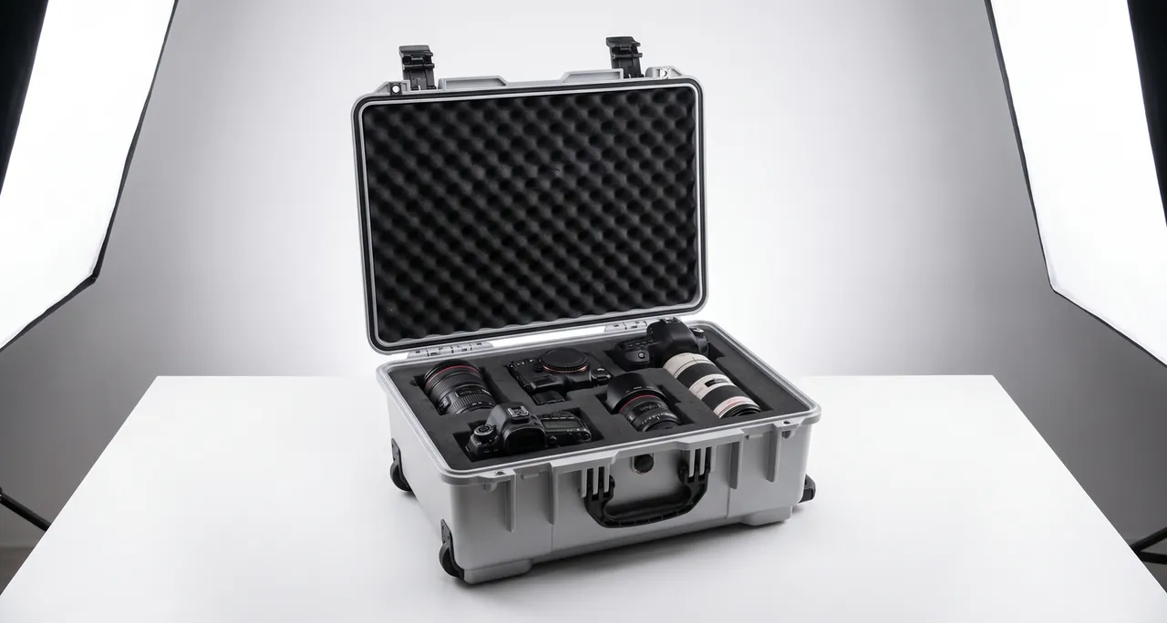
Life verification cannot simply count cycles. A meaningful accelerated sequence combines open-close cycles, dust dosing and humidity-temperature cycling: JUNZHIJIA doses test dust every 500 cycles, repeats an eight-hour dust test every 1000 cycles, and requires the rating after 5000 cycles to stay within one level of the initial result. Maintainability belongs in the same review: seals must be replaceable by hand, grooves need a feature preventing reversed assembly, and documentation should state the seal part number and change interval.
Material Modulus and Shell Stiffness Behind Seal Durability
Seal stability rests on shell stiffness. However good the seal profile, lid deflection under clamp or external load drops local contact stress below threshold and dust enters at that spot. The issue is scale: an elastomer offers a limited compression range, typically 0.5 to 3 mm, while shell deflection can easily exceed it.
Elastic modulus is the first variable: polypropylene measures roughly 1.0 to 1.6 GPa in flexure, polyethylene 0.4 to 1.0 GPa, PC/ABS alloy 2.0 to 2.6 GPa and aluminium about 69 GPa. Low-modulus materials are tough but short on stiffness and need thickness and ribbing; high-modulus materials are stiff but more brittle and expensive. In dust service JUNZHIJIA does not recommend adding wall thickness, because thick sections bring sink marks, warp and weight. The efficient route is a thin wall with dense ribbing and well-distributed clamp points.
| Material | Flexural modulus at room temperature | Retention at 60 °C | Design implication |
|---|---|---|---|
| --- | --- | --- | --- |
| Rotomoulding PE | 0.4–1.0 GPa | About 40–55% | Thick sections, dense clamp points |
| Injection PP | 1.0–1.6 GPa | About 45–60% | General purpose, needs ribbing |
| Glass-filled PP | 2.5–4.5 GPa | About 55–70% | Good hot stiffness, watch fibre bloom |
| PC/ABS | 2.0–2.6 GPa | About 70–85% | Precision cases, higher cost |
| Aluminium | About 69 GPa | About 95% | Best stiffness, manage galvanic risk |
Temperature must be carried into the calculation: polypropylene at about 1.3 GPa at room temperature can fall below 0.6 GPa at 60 °C, a loss of more than half. A case that passes on the bench may lose clamp force in a sun-loaded enclosure, so high-temperature verification cannot stop at heat ageing of the seal compound; it must include a dust re-test at temperature. Material behaviour is covered in Plastic Materials for Protective Cases. Rib layout decides how efficiently modulus is used: a continuous ring rib inboard of the groove raises section inertia, radial short ribs between latches spread clamp load along the seal band, rib thickness sits at 0.5 to 0.7 of wall and height at two to four times wall.
Latch, Hinge and Clamp Force Distribution
Clamp force distribution is the most underestimated part of dustproof design. A seal only works where it is compressed, and compression comes from the latches; too few or too widely spaced, and a pressure decay zone opens on the seal band between fixing points, exactly where dust enters first. The practical rule is one clamp point every 150 to 250 mm along the perimeter, relaxed on the hinge side but tightened at corners.
Magnitude has to match the seal: a hollow bulb at 50 Shore A needs roughly 30 to 80 N of line load per 100 mm, about 100 to 300 N per latch. Too little leaves the joint open; too much accelerates compression set and spoils opening feel. JUNZHIJIA measures pressure distribution with indicating film before tooling release and freezes latch specification and torque only after confirming no low-pressure zone.
| Design factor | Recommended practice | Common mistake |
|---|---|---|
| --- | --- | --- |
| Clamp spacing | 150–250 mm, tighter at corners | Corner latches only, no mid-span |
| Force per latch | 100–300 N to suit the seal | Set by feel, never quantified |
| Hinge side | Continuous hinge or extra points | No compensation at hinge |
| Latch type | Compression cam or toggle | Plain over-centre catch |
| Marking | Closing torque stated on the plate | No marking, arbitrary field practice |
Latch mechanism matters too. A compression latch generates a downward component as it closes and actively presses the lid onto the seal, whereas a simple catch supplies only tension and relies on lid weight and stiffness, failing badly on light lids or vertical mounting. For frequently opened cases JUNZHIJIA combines a compression latch with a quick-release action and a clear visual closure indicator. The interaction is examined in Hinges, Latches and Seals in Toolboxes.
Liners and Compartments as a Second Line of Defense
Even a shell rated IP6X admits dust in real service, through air exchange whenever the case is opened and particles carried in on tools, samples or gloves. Dust protection therefore needs a second line inside the case. Liner selection for dust service differs from cushioning selection: cushioning cares about density, resilience and energy absorption, while dust service cares about shedding and cleanability. Open-cell foam sheds crumbs and cannot be wiped, whereas closed-cell EPE, EVA and IXPE have a dense skin that wipes clean and can be given an antistatic finish. Trade-offs are set out in EPE versus EVA Foam for Toolboxes.
Compartmentalisation reduces the area exposed at each opening. A single large cavity exposes everything every time the lid is raised, which on a dusty site means one ingestion event per access; independent compartments with their own drawers, flaps or doors cut cumulative ingress by roughly an order of magnitude. Dividers should shield as well as separate, so they do not become migration paths. Practice is covered in Removable Divider Systems for Cases.
| Second-line measure | Mechanism | Where it fits |
|---|---|---|
| --- | --- | --- |
| Closed-cell liner | Wipeable, non-shedding surface | General use, precision payloads |
| Antistatic treatment | Reduces electrostatic attraction | Coal, carbon and plastic dust |
| Inner lid or dust curtain | Shields main cavity when open | Frequently accessed tool cases |
| Independent compartment doors | Smaller exposed area per access | Mixed payloads |
| Removable washable liner | Periodic full cleaning | Long field deployments |
Cleanability is a whole-life property: exterior surfaces should avoid deep recesses and unwipeable textures, internal corners should use cleanable radii, and liners should lift out for washing. JUNZHIJIA ships a cleaning and maintenance card with custom projects stating cleaning frequency, approved agents and the seal change interval.
Industry Application Matrix and Selection Checklist
Dust characteristics vary enormously between industries, so selection should start from dust type, concentration, exposure duration and opening frequency, then work backwards to the configuration. The matrix below gives starting points only.
| Industry or site | Dust character | Starting configuration | Critical verification |
|---|---|---|---|
| --- | --- | --- | --- |
| Cement and building materials | Fine, cakes when damp | IP6X, twin lip, dust-tight vent, closed-cell liner | Eight-hour dust test plus hot re-test |
| Quarrying and mining | Quartz, highly abrasive | Labyrinth pre-stage, wiper lip, hard face | Dust re-test after 3000 cycles |
| Solar and wind service | Fine sand, UV, wide daily swing | IP6X, high-flow vent, UV-stable shell | Thermal cycling plus dust re-test |
| Metalworking | Conductive swarf with oil mist | Double seal, oleophobic vent, antistatic liner | Combined oil mist and dust test |
| Chemical powder handling | Fine, possibly combustible | Positive pressure, antistatic shell, grounding | Leakage rate and supply-loss hold |
| Field medical response | Moderate dust, frequent access | IP5X main cavity, inner lid | Cycle life and cleanability |
The selection sequence reduces to five steps: quantify particle size and hardness; decide the permissible ingress quantity, which sets IP5X or IP6X; choose seal form and labyrinth stages; match vent and clamp points; then define verification and maintenance. The first step is most often skipped and drives every subsequent cost. Where water protection is also in scope, the second numeral can be settled with reference to IP65, IP66 and IP67 Differences.
Acceptance Criteria and Incoming Inspection Plan
Acceptance operates at three levels: type testing, a full verification once at design freeze; routine production testing, a quick check on every unit; and incoming inspection, sampling seal and membrane batches. Drop any one and production consistency cannot be claimed.
Type testing covers the dust test to the target rating, cycle life testing, a dust re-test after thermal cycling and under stacking load, vent airflow measurement, and seal hardness and compression set. Routine testing can substitute a cheaper proxy, most usefully a pressure decay check in which a small positive pressure is introduced and the rate of loss measured. It is not equivalent to the dust test, but it reliably rejects units with seal assembly faults.
| Inspection item | Method | Criterion | Frequency |
|---|---|---|---|
| --- | --- | --- | --- |
| Dust rating | Eight-hour chamber test | Per IP5X or IP6X | Type and annual |
| Air tightness proxy | Pressure decay | Decay rate within limit | Every unit |
| Seal hardness | Shore A durometer | Specification plus or minus 5 | Incoming sample |
| Seal dimensions | Calliper or projector | To drawing tolerance | Incoming sample |
| Latch clamp force | Force gauge | 100–300 N | Production sample |
| Vent airflow | Flow bench | Not below specification | Incoming sample |
| Internal cleanliness | White cloth comparison | No visible deposit | Type testing |
JUNZHIJIA ships a summary of these records with production batches and fixes the numerical criteria and sampling plan, normally referenced to an AQL level, in the technical agreement. For custom programmes the acceptance standard should be signed before tooling starts. A fuller treatment is given in Custom Case Acceptance and AQL.
Frequently Asked Questions FAQ
Q: Should I always specify IP6X, or is IP5X enough in practice?
A: The decision turns on where the dust lands and whether it can cause harm, not on picking the larger number. IP6X requires that no dust enters at all, which means a continuously closed joint, a vent element that is itself dust-tight, and enough shell stiffness to hold clamp force through thermal soak and stacking load, all of which raise cost, weight and opening effort. Where the payload is not dust sensitive, or where any deposit lands on non-functional surfaces and does not affect cooling or insulation, IP5X is entirely adequate and gives better opening feel and longer seal life. The moment dust can reach a circuit board, a connector, an optical window or a precision motion pair, specify IP6X and require the vent and cable entries to meet the same level. JUNZHIJIA asks customers to declare a sensitive-area list before the rating is fixed, because that list is what actually drives the cost of the design.
Q: Why does a dustproof case need a vent at all, and does fitting one let dust in?
A: A vent is necessary, and a correctly specified one does not admit dust. A rigid, fully sealed enclosure develops a real pressure differential whenever temperature or altitude changes: a case of a few tens of litres cycling through a daily swing of several tens of degrees sees several kilopascals, and transport to altitude is worse. That differential either deforms the lid, opens the joint momentarily or makes the case impossible to open, and dust is drawn in precisely during those breathing moments. A filter vent uses an expanded PTFE membrane whose pores are in the sub-micron to few-micron range, far below the size of virtually all airborne dust, while still passing enough air to equalise pressure. What actually causes ingress is not fitting a vent but specifying one with an inadequate rating, failing to seal the vent housing to the shell, or mounting it facing the dust stream so the membrane clogs and then fails.
Q: How often should a filter vent membrane be replaced, and what happens when it clogs?
A: The interval depends on dust loading, humidity and mounting position. A dry, leeward location protected by a pre-filter can run for more than a year, while a dusty, humid site with no shielding may clog in three to six months. The direct way to decide is to measure airflow at a specified differential and replace once flow falls below an agreed fraction of the rated value. Clogging progresses through three stages. At first, pressure equalisation simply becomes slower and nobody notices. Next, the case visibly balloons or is sucked in during rapid temperature changes and the lid feels heavy to open. Finally, the joint is forced open repeatedly under differential pressure, dust is drawn in quantity, and the lid and latches carry loads they were never designed for, which can lead to permanent deformation. Vents should therefore be on the periodic inspection list, with a pre-filter and shield added in heavy dust.
Q: Is positive pressure dust protection worth the investment?
A: The deciding metric is the ratio between system leakage rate and the supply capacity of the air source. Measure leakage first, using a pressure decay test at the intended set point. If the pump or cylinder can comfortably outpace that leakage, the enclosure will hold pressure indefinitely and the concept is sound. If it cannot, the system spends most of its life below set point, consuming air or power without delivering protection, and the right move is to improve the passive sealing before considering positive pressure at all. Three cost lines need to be added up: capital, covering the air source, filtration and drying, pressure monitoring and overpressure relief; running cost, covering power or gas and filter changes; and maintenance, covering inspection labour and response to supply loss. Positive pressure fails abruptly rather than gradually, so unattended sites need monitoring and alarm. Where the case is opened often, the same check should be repeated after a few weeks of service, because a gasket that has taken a permanent set will let fine dust past even though the case still closes with normal resistance. Q: Silicone or EPDM for the seal, and how should hardness be set in dusty service?
A: Neither is universally better; the choice follows the media and the temperature range. Silicone has the widest temperature window, stays flexible at low temperature and shows the lowest compression set, which suits outdoor cases with large daily swings or genuine cold exposure, but its tear and abrasion resistance is only moderate and sharp particles can cut the lip. EPDM offers excellent weathering and ozone resistance at low cost but swells in mineral oil, so it is wrong for metalworking environments where oil mist and dust coexist, where NBR or FKM is the correct substitution. Hardness involves a genuine compromise in dust: softer compounds around 40 to 50 Shore A conform well to imperfect faces but accept embedded particles more readily, while harder compounds near 60 to 70 Shore A resist embedding but need more clamp load for the same contact stress. JUNZHIJIA normally specifies 50 to 60 Shore A for small cases with good flatness and dense clamp points, and 40 to 50 for large lids where stiffness compensation is also applied.
Q: After a year in a dusty site the lid no longer closes tightly; what is happening?
A: The most common cause is compression set in the seal acting together with dust packed into the groove. A seal held in compression for months and exposed to heat progressively loses its ability to recover, which shows up as a lid that closes with less resistance and latches that still feel loose when engaged. At the same time, accumulated dust in the groove props the seal up locally and opens a gap you can actually see. Because the two mechanisms accelerate each other, replacing the seal without cleaning the groove, or cleaning the groove without checking rebound, only half fixes the problem. Three further checks are worth making: whether latch wear has reduced the compression stroke, whether hinge slack has shifted the lid out of alignment, and whether the lid itself has taken a permanent set from long-term stacking or heat. Treating seals as planned consumables with a defined change interval avoids reaching this point at all.
Q: Can the dust test and the water test be combined into a single run?
A: They should not be combined, and the sequence matters if both are required. The dust test uses dry talcum powder and the water test uses water; mixing them produces a caked slurry that contaminates the equipment and destroys the verdict, because any powder left on the seal absorbs water and turns to paste, making it impossible to tell a genuine seal failure from residue. The accepted approach is to run the dust test first, clean and dry the sample thoroughly, then run the water test, or simply to use two separate samples. If water must come first, the case has to be completely dried and every trace of moisture and residue removed from the seal groove before it enters the chamber, otherwise powder adheres to damp surfaces in quantity and the severity of the test is no longer controlled. JUNZHIJIA normally schedules two independent samples so that neither result can be compromised by the other.
Q: What information should I give a manufacturer to get a custom dustproof case right first time?
A: Six categories of information are needed. First, the dust itself: type, particle size distribution, hardness, concentration, and whether oil mist or electrostatic behaviour is involved. Second, the target rating and its verdict: IP5X or IP6X, and whether a water rating is required at the same time. Third, the service conditions: volume, payload, number of stacked layers, temperature range, altitude change and expected opening frequency. Fourth, payload sensitivity: which zones count as sensitive and whether any deposit at all is tolerable there. Fifth, the interfaces, since vents, cable entries, display windows and external terminals are the usual weak points in an otherwise sound design. Sixth, verification and documentation: which type tests are required, the sampling plan, and the document set to ship with each case.
Conclusion and Related Reading
JUNZHIJIA builds dustproof cases around verifiable performance: quantify the dust, engineer the seal and vent together, and hold production to the same criteria as the qualified sample. Custom tooling, OEM and ODM programmes and accompanying documentation are available.
Related Reading