

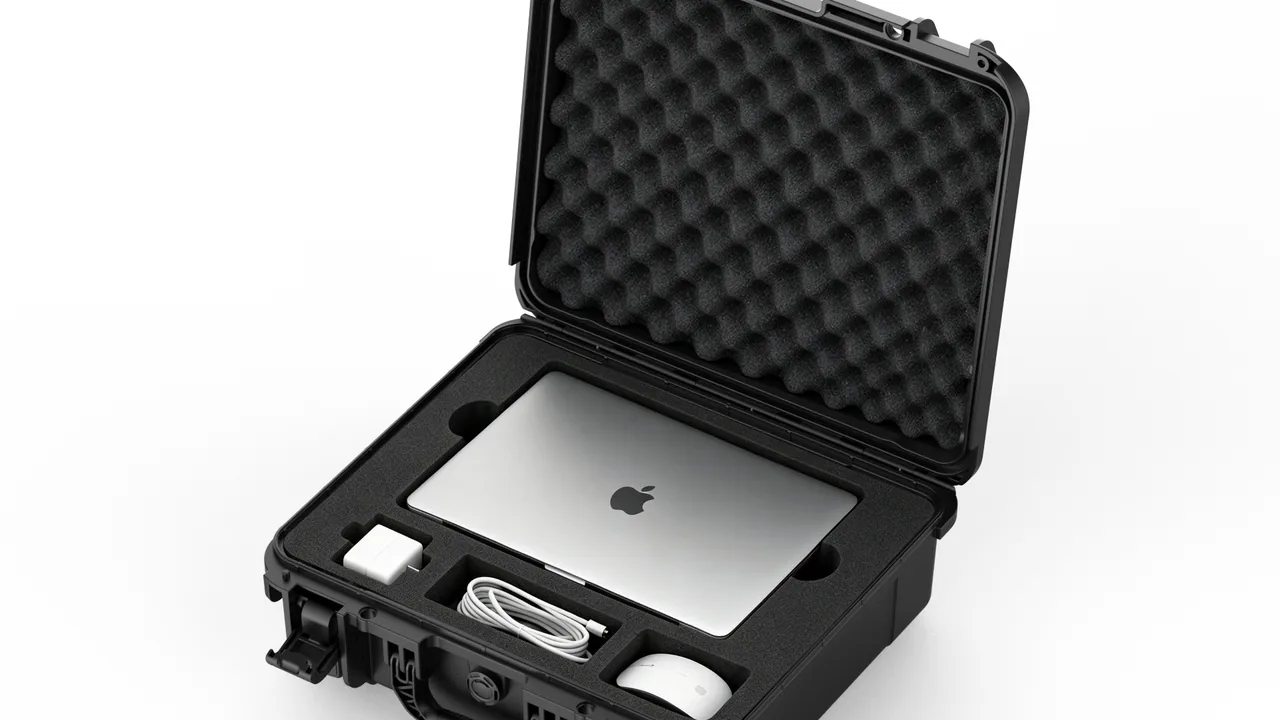
The diaphragm of a condenser microphone is between 1.5 and 6 micrometres thick, roughly one tenth of a sheet of cling film, carrying a vapour-deposited gold layer a few nanometres deep as its electrode. The gap between that diaphragm and the backplate sits between 20 and 50 micrometres, and normal working displacement is measured in nanometres. What this structure must survive is stacking pressure inside a tour container, drops from a baggage belt, and hours of vibration in a broadcast van. The difficult part is that microphone damage rarely reads as failure; it reads as drift. Sensitivity moves by one or two decibels, self-noise rises, the top end collapses slightly, and a mixing engineer compensates with EQ until the moment someone notices the sound is simply not right, long after any single journey could be blamed.
JUNZHIJIA applies a specific protection principle to audio capture equipment: refine the objective from "the microphone must not break" to "the acoustic character must not drift", by setting separate shock, humidity and electrostatic thresholds for the diaphragm, the contacts and the electronics, so that every microphone arrives with the frequency response recorded at the factory. Executing that principle means classifying sensitivity first, then assigning liner density and cavity tolerance by class, and finally closing the loop with desiccant, labelling and periodic re-measurement.
Table of Contents
- Vulnerability Map of Capture Systems
- Condenser, Dynamic and Ribbon Differences
- Shock and the Diaphragm
- Humidity, Salt Fog and Mould
- Cushioning Liners and Cavity Tolerance
- Compartment Layout Logic
- Wireless System Requirements
- Shell Structure and Hardware
- Sealing and Desiccant Management
- Handling, Stacking and Airline Check-In
- Labelling, Count-Out and Traceability
- Acceptance, Cleaning and Service Life
- Frequently Asked Questions FAQ
- Conclusion and Related Reading
Vulnerability Map of Capture Systems
A capture system is not one device but a chain: transducer plus suspension plus electronics plus transmission, and each link has a different failure threshold. The transducer is the most fragile, sensitive to shock, humidity, static and air movement. The suspension fears plastic deformation and thread damage. The electronics fear solder fatigue, battery leakage and interference. The transmission path fears fretting wear and conductor fatigue.
Turning those four groups into measurable inputs produces the reference table below.
| Element | Sensitive load | Typical failure | Measurable metric | Working threshold |
|---|---|---|---|---|
| --- | --- | --- | --- | --- |
| Diaphragm and backplate | Shock, humidity, static | Set, debonding, mould | Sensitivity, response | Drift under 1 dB |
| Shock mount | Static load, shock | Element yield, cord ageing | Isolation frequency | 8 to 15 Hz |
| Impedance converter | Vibration, moisture | Solder cracking, leakage | Self-noise | Rise under 2 dB(A) |
| XLR contacts | Vibration, corrosion | Rising contact resistance | Contact resistance | Under 10 milliohms |
| Cable conductors | Repeated bending | Strand breakage | Continuity, shield | Shield under 50 milliohms |
| Wireless transmitter | Shock, batteries | Antenna loosening, leakage | RF output power | Deviation under 1 dB |
The table exposes a fact that is routinely missed: acoustic failure in microphones is almost always a downstream consequence of mechanical or chemical failure. The diaphragm has not torn, but charge on the backplate has decayed through an adsorbed water film, so sensitivity drops. The connector has not broken, but wear through the gold flash has pushed contact resistance from 5 to 50 milliohms and raised the noise floor. Protection design therefore targets those indirect paths rather than visible destruction. JUNZHIJIA normally begins a broadcast or touring programme by requesting the microphone schedule and recent calibration records, then classifies sensitivity before assigning liners.
Condenser, Dynamic and Ribbon Differences
Different transduction principles demand very different protection, and one universal foam slot for every microphone is the most common field error.
A condenser microphone works from the capacitor formed by diaphragm and backplate. Diaphragm thickness is 1.5 to 6 micrometres under very low tension, and true condenser types require 48 volt phantom power. Three weaknesses dominate: humidity changes the polarisation state and invites mould, shock drives the diaphragm past its elastic limit, and electrostatic discharge destroys the field-effect transistor in the impedance converter. Each unit needs its own cavity with no hard contact, plus desiccant.
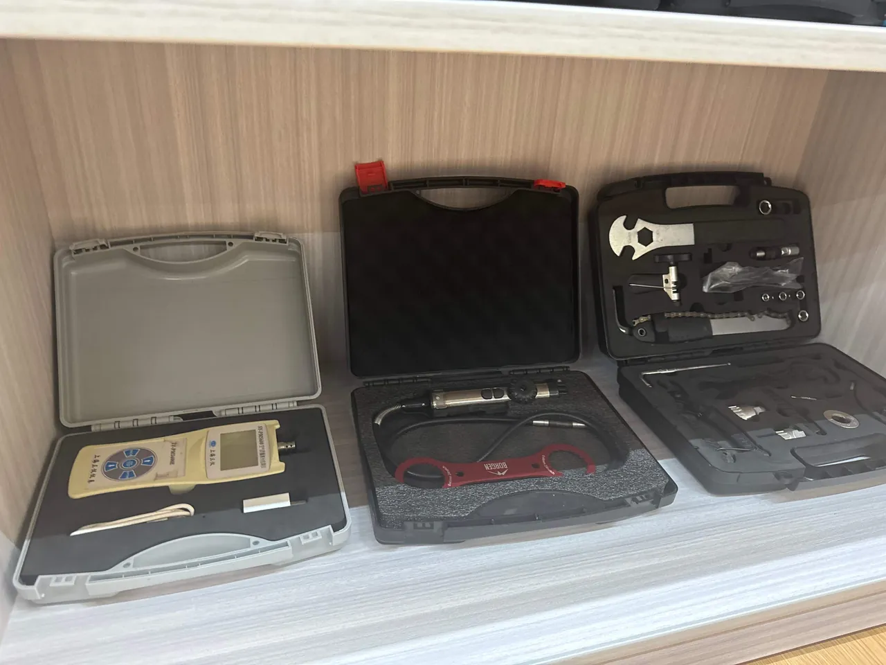
A dynamic microphone moves a voice coil bonded to a diaphragm of roughly 25 to 50 micrometres inside a magnetic gap, giving far greater mechanical strength and low humidity sensitivity. It has two exclusive risks instead: strong external fields can shift the magnetic operating point, so it should travel away from loudspeakers and large transformers, and a severe drop can shift the coil in the gap, producing rub and distortion that never recovers.
Ribbon microphones are the most fragile class. The ribbon is only 1 to 2 micrometres thick, suspended under its own tension in a strong field, and acceleration in any direction can stretch it permanently. Ribbons also fear air movement, even close speech, and phantom power, since an accidental 48 volts fuses the element. They must travel upright in the manufacturer's bag with no possibility of swinging.
| Type | Diaphragm | Shock tolerance | Humidity sensitivity | Exclusive risk | Storage rule |
|---|---|---|---|---|---|
| --- | --- | --- | --- | --- | --- |
| True condenser | 1.5–6 micrometres | Low | Very high | ESD, polarisation decay | Single cavity plus desiccant |
| Electret | 2–6 micrometres | Low | High | Irreversible charge loss | Single cavity plus desiccant |
| Dynamic | 25–50 micrometres | Medium-high | Low | Coil rub, magnet shift | Keep from strong fields |
| Ribbon | 1–2 micrometres | Very low | Medium | Air blast, phantom power | Upright in soft bag |
| Wireless handheld | As dynamic | Medium | Medium | Antenna base loosening | Remove batteries |
Shock and the Diaphragm
Understanding why microphones fear shock starts with the relationship between sound pressure and diaphragm displacement. A condenser rated at 20 millivolts per pascal with a 140 decibel maximum level moves only a few micrometres at its limit, because every 6 decibels doubles pressure and displacement. 140 dB SPL equals 200 pascals, which across a 20 millimetre diaphragm is about 0.063 newtons, a remarkably small force that reveals how low the mechanical impedance really is.
Working backwards, a drop exposing the microphone to 500 G multiplies the diaphragm's own weight by five hundred. The diaphragm mass is measured in milligrams, but the tensioned structure supporting it can carry far less, so displacement under shock easily reaches hundreds of times the working value. That is the physical origin of a microphone that looks undamaged yet sounds different: the diaphragm has not ruptured, but its support has yielded or partly debonded, the tension distribution has changed, and the response has moved with it.
A shock mount provides isolation at exactly this point. A typical four-point elastic suspension has a natural frequency of 8 to 15 hertz and attenuates strongly above 30 hertz. It only works while healthy, because elastic elements creep under sustained load and rubber cords lose compliance after two to three years, raising the isolation frequency. The field test is simple: nudge the mounted microphone and time the free oscillation; a period noticeably shorter than the design value means the element has hardened.
One further mechanism deserves attention, the transient air pressure pulse inside the case. At the instant of impact the trapped air compresses and a pressure wave acts on every internal surface. For a structure of such low mechanical impedance that wave is equivalent to a high-level acoustic transient. This is why filling a case with soft foam cannot replace a rigid dedicated cavity: foam blocks solid load paths but not airborne ones. The effective answer places each microphone in a relatively enclosed cavity separated from the main volume by foam walls, which attenuates the transmitted wave.
Humidity, Salt Fog and Mould
Humidity is the primary enemy of condenser microphones and it attacks through four parallel routes. Polarisation decay: an adsorbed water film raises surface conductivity so stored charge leaks away and sensitivity falls irreversibly. Mould growth: organic residue on the diaphragm becomes a culture medium, and hyphae alter mass distribution and damping. Corrosion: pores in the gold flash expose nickel or copper, which corrodes electrochemically and lifts contact resistance. Condensation: moving a cold microphone into warm humid air wets the grille immediately and water tracks inward to the diaphragm.
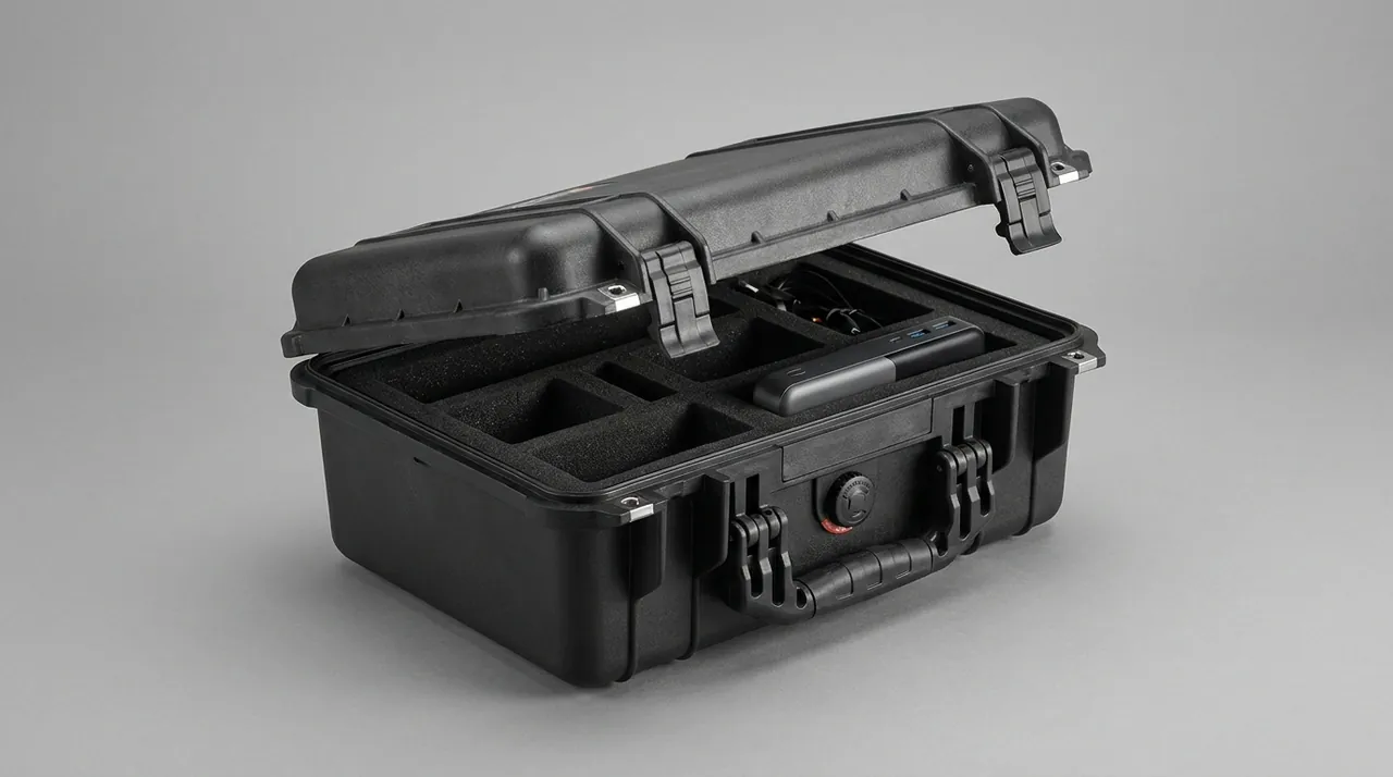
Sixty percent relative humidity is the warning line and seventy percent the loss-of-control line. Below forty percent, mould and corrosion rates drop sharply, but below twenty percent some rubber elements and fabric linings embrittle. The ideal storage window is 40 to 55 percent at 15 to 25 degrees Celsius.
Coastal and marine work adds salt aerosol. Sodium chloride settling on grilles and plating absorbs moisture to form an electrolyte film, and corrosion proceeds roughly an order of magnitude faster than in clean humid air. GB/T 10125 neutral salt spray serves as a screening test for plating and grille materials, commonly 48 to 96 hours without red rust, though it is an accelerated comparison method and not a service-life prediction.
Desiccant is the executing control and its quantity must be calculated from case volume and exposure, not guessed. Silica mass in grams is approximately case volume in litres multiplied by 0.8, by the number of exposure months, and by a humidity factor above 1.5 for tropical routes and around 1.0 for dry ones. Keep desiccant in a vented box that never touches a microphone, so silica dust cannot reach the diaphragm, and fit an indicator card read at first opening and logged in the equipment record. Regenerate indicating silica at 120 degrees Celsius for two hours.
Cushioning Liners and Cavity Tolerance
Microphones are small and expensive, so liner design should optimise accuracy rather than thickness. Cavity tolerance decides whether a microphone has any freedom to move, and micro-motion is the root of wear and fatigue.
Cavity clearance should sit between plus 0.5 and plus 1.5 millimetres over the body. Too much clearance lets the microphone strike the cavity wall under shock; too little makes retrieval hard and applies continuous restoring pressure that can deform a grille over long storage. Where a microphone carries switches or pattern selectors, the cavity needs a relief pocket so the lever's spring element is not held under permanent load.
Material selection favours EVA or high-density EPE. EVA at 60 to 120 kilograms per cubic metre is stiff enough to hold crisp cavity edges while still cushioning, and suits the structural skeleton. High-density EPE at 35 to 60 kilograms per cubic metre is light and cheap, suiting divider walls and filler blocks. Facing layers should be IXPE or fabric, which have low friction and will not scuff grilles or plating.
| Position | Material | Density | Function | Common error |
|---|---|---|---|---|
| --- | --- | --- | --- | --- |
| Structural skeleton | EVA | 60–120 kg/m3 | Cavity location, load bearing | Density too low, cavity collapses |
| Divider walls | High-density EPE | 35–60 kg/m3 | Isolation, pressure wave damping | Walls too thin |
| Facing layer | IXPE or fabric | 30–80 kg/m3 | Anti-scuff, low friction | Ordinary sponge sheds |
| Base cushioning | EPE | 20–35 kg/m3 | Drop travel absorption | Too thick, causes sway |
| Lid pressure pad | EVA with fabric | 60–100 kg/m3 | Prevents ejection | Over-compression distorts |
Two chemical constraints apply alongside the mechanical ones. Electrostatic control comes first, because the impedance converter is extremely ESD sensitive and ordinary foam can discharge enough energy to destroy it, so materials at 10 to the sixth through 10 to the ninth ohms surface resistance are required. Low outgassing comes second, since some reclaimed-content foams release species that condense as haze on grilles and plating, so JUNZHIJIA runs a 70 degree Celsius, 24 hour check on every incoming lot. Process comparisons appear in EVA Foam Insert Custom Process and Case Pick and Pluck Foam.
Compartment Layout Logic
Compartment design answers one question: does every item have exactly one stable position, and does that position create no hard contact path to anything else. For multi-microphone kits this single question decides whether a return-to-factory calibration is needed after every tour leg.
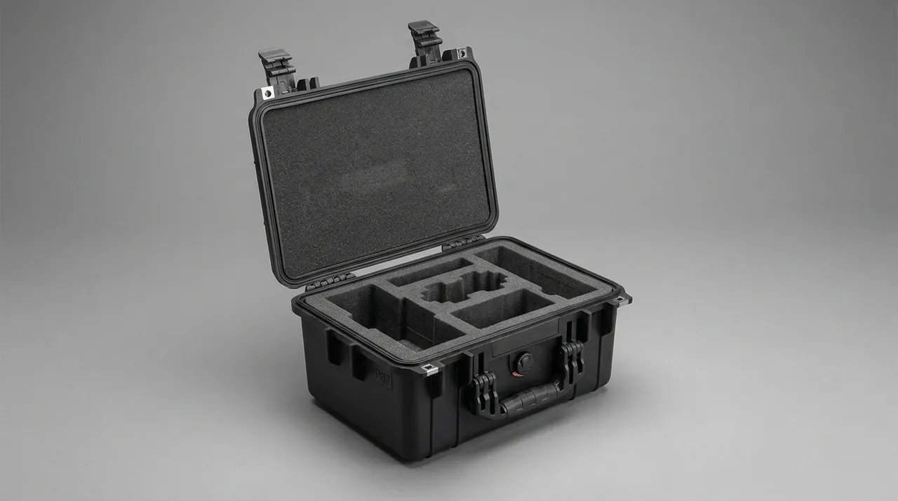
The body zone is the core. Each microphone needs its own cavity, walls between cavities at least 12 millimetres thick, and cavity depth covering 60 to 80 percent of body length so shock cannot eject it while enough grip space remains. A consistent horizontal orientation with grilles facing inward means that even if a cavity loosens slightly the grille cannot strike a neighbouring wall. Ribbon microphones are the exception and must stay upright or in the maker's specified attitude.
Shock mounts involve a genuine trade-off. Keeping them fitted means instant setup and fewer lost parts, but elastic elements creep under sustained load and cords age. JUNZHIJIA grades by trip length: single-day remotes keep mounts fitted, while tours beyond three days separate them into dedicated cavities, stored in a natural attitude and checked periodically for free oscillation period.
Windscreens and pop filters are soft bulky items that too often get stuffed into voids, which is wrong. Foam windscreens take permanent compression set under sustained load and no longer seal to the head, changing acoustics. Give them a shallow cavity slightly deeper than their natural height with no compression. Fur windscreens fear pressure even more and belong in a lid-side mesh pocket in their own bag.
Cables and connectors cause the most repeat failures. Coil XLR leads loosely, never below a 200 millimetre diameter, because tight bends fatigue conductors; secure with hook-and-loop straps rather than rubber bands, which perish and leave residue. Spare adapters and hardware go in a lidded parts box. Batteries must come out of every transmitter and body before packing, which serves both leak prevention and air transport rules.
Poka-yoke and labelling complete the compartment. Multiple identical microphones are easily confused, so every unit needs a unique number marked beside its cavity, with a layout diagram and count-out list on the inside of the lid. Where a cavity has ambiguous orientation, build in an asymmetric feature. This discipline is set out further in Precision Instrument Protective Cases.
Wireless System Requirements
Wireless microphone systems carry three risks that wired microphones do not: batteries, antennas and frequency management.
Batteries come first. Alkaline cells left in equipment leak, and electrolyte wicking into a circuit board causes irreversible corrosion at a repair cost approaching replacement. Lithium cells add regulatory exposure, because ICAO and IATA dangerous goods rules cap state of charge at 30 percent for cells shipped alone, require UN38.3 qualification, and limit packaging, quantity and declaration, so non-compliant shipments are stopped at security. Whatever the chemistry, remove cells before packing, place them in a dedicated battery box with electrodes insulated by tape or individual slots, store that box in its own cavity away from the bodies, and mark cell type and quantity on the case exterior.
Antennas come second. On handheld transmitters the antenna base is a small threaded or bayonet joint that loosens under repeated shock, reducing radiated efficiency and range. On bodypack transmitters the antenna is a flexible lead whose conductor can fracture from tight bending with no external sign. Transport antennas in a natural extended attitude or as the maker recommends, never trapped under equipment.
Frequency management looks unrelated to transport but is tightly coupled to it. Available spectrum differs by country, so cross-border tours need coordination completed before departure and documented in the case file, including any licences or permits required for local inspection. There is also a practical hazard in dense storage: if one transmitter powers on unintentionally it generates intermodulation against the others, so confirm every unit is off before closing the lid.
| Component | Principal risk | Transport measure | Inspection item |
|---|---|---|---|
| --- | --- | --- | --- |
| Handheld transmitter | Cell leakage, loose antenna | Remove cells, antenna relaxed | RF power, antenna tightness |
| Bodypack transmitter | Antenna fracture, clip set | Own cavity, no stacking | Pull test, continuity |
| Receiver | Panel impact, BNC loosening | Panel inward, port caps | Port tightness, display |
| Batteries | Leakage, air rules | Dedicated box, insulated | Appearance, voltage |
| Antenna distributor | Port deformation | Port caps, lay flat | Port continuity |
Shell Structure and Hardware
Microphone cases are usually small and medium enclosures, and their design priorities differ from large rack cases: opening cycle life, seal stability and efficient use of internal volume matter more than extreme stacking capacity.
Three material routes serve this size. Injection-moulded ABS or PP is light, dimensionally accurate and well finished, suiting kits of two to eight microphones, with the caveat of modest low-temperature impact resistance. Rotomoulded PE offers toughness, uniform wall and strong corners for checked baggage and rough handling, at the cost of looser tolerances that need liner compensation. Aluminium frame construction gives the best strength-to-weight ratio and a professional appearance for fixed storage and frequent access, but corners are the weak point and cost is higher. JUNZHIJIA typically recommends rotomoulded or injection shells with an EVA liner skeleton for touring work.
Hardware selection determines real service life. Latches should be metal or high-strength engineering plastic rated to at least 10000 cycles and must give clear confirmation when closed, since an unlatched case opening during handling is a standard touring accident. Hinges should be full-length or concealed so nothing protrudes into a stack. Handles must balance both empty and loaded, preventing the case from tipping forward when carried.
Refined use of internal volume distinguishes a good small case. A lid-side mesh pocket or elastic band holds documents and fur windscreens; a shallow base drawer takes cables and the parts box; a moulded recess in the inner wall locates the desiccant box. None of these add much cost and all raise field efficiency. Layout thinking from Cushion Liner Cases transfers well here.
Sealing and Desiccant Management
Microphone transport does not need immersion protection, but it does need a stable low-humidity interior and dependable dust exclusion.
Under IEC 60529 and GB/T 4208 the sensible range is IP54 to IP65. The first digit should be 5 or 6, and 6 is recommended for condenser work, because any particulate settling behind the grille changes the diaphragm's mass loading and damping and therefore the top-end response. The second digit of 4 covers loading in rain and brief dock exposure; 5, protection against jets, suits open stages and wet-season touring.
Three details decide whether a seal performs. Gaskets should be EPDM or silicone at 40 to 55 Shore A with compression set under 25 percent. Groove compression should be 20 to 30 percent of free gasket height. Latch count and spacing must stop the lid bowing along its long edge, and on smaller enclosures two latches suffice provided they sit symmetrically at opposite ends rather than on the same side.
The drying system is a mandatory companion to sealing. Beyond the silica quantity formula, three operational points matter: fix the desiccant box in a dedicated internal recess so it cannot roll against a microphone; use a vented but dust-tight container such as a perforated plastic box or a metal box with a nonwoven liner; and mount the humidity indicator where it is read at first opening, normally inside the lid. JUNZHIJIA specifies regenerable indicating silica for touring programmes and documents regeneration at 120 degrees Celsius for two hours. Related practice appears in Outdoor Case Rain and Humidity.
Handling, Stacking and Airline Check-In
Load spectra differ sharply by scenario and each demands a different emphasis.
Touring container transport means long duration, repeated handling and dense stacking, dominated by sustained low-frequency vibration and static stack load rather than high single shocks. Limit stacking to five layers and place microphone cases above rather than at the bottom.
Outside broadcast vehicles add random vibration and thermal shock. Urban roads concentrate energy near 3 to 8 hertz from the suspension and again at 20 to 60 hertz from road texture and body panel resonance. The thermal risk is condensation: opening a case straight out of an air-conditioned vehicle lets humid air condense on a cold grille. Let the case equilibrate in the destination environment for one to two hours before opening.
Checked airline baggage is the harshest case. Belt systems drop from 0.5 to 1.2 metres in random attitudes, and cruise holds sit near 0.75 atmospheres, or 0.6 when unpressurised, producing a differential of 0.25 to 0.4 atmospheres. Three requirements follow: all-round cushioning valid in any attitude, meaning foam on all six directions and a lid pad that reliably prevents ejection; a pressure equalization valve with an expanded PTFE membrane passing 100 to 500 millilitres per minute at 7 kilopascals; and a shell with genuine corner impact strength. Mark the exterior as precision instruments with an up arrow, and remember the valve manages pressure, not moisture, so desiccant stays in.
| Scenario | Dominant load | Typical magnitude | Protection emphasis |
|---|---|---|---|
| --- | --- | --- | --- |
| Touring container | Sustained vibration, stacking | 0.3–0.6 Grms, five layers | Layer limit, isolation, retention |
| Broadcast vehicle | Random vibration, thermal shock | Peaks at 3–8 and 20–60 Hz | Equilibrate before opening |
| Checked baggage | Random drop, low pressure | 0.5–1.2 m, 0.6–0.75 atm | All-round cushioning, valve |
| Manual handling | Drop, impact | 50–200 G single event | Handles, corner reinforcement |
| Warehouse storage | Static load, humidity | 40–55 percent RH | Desiccant, periodic checks |
Labelling, Count-Out and Traceability
The hard part of managing a multi-microphone kit is the count. A sixteen-microphone drum kit with shock mounts, cables, windscreens, transmitters, receivers and batteries easily exceeds eighty separate items, and any single omission stops the session.
Traceability rests on a three-level coding scheme. Level one is the case identifier, unique and marked outside with a content summary, weight and responsible person. Level two is the position code, a fixed reference such as A1 or B1 for every cavity and compartment. Level three is the asset number on each device, tied to its calibration record. One layout diagram links the three levels, fixed inside the lid and mirrored in a digital file.
Count-out should be a fixed ritual at three points: before departure, on arrival and before return, working cell by cell against the diagram rather than from memory. A digital variant places a two-dimensional code at each cavity so a phone scan highlights missing items automatically. JUNZHIJIA can pre-apply those labels on volume programmes and align them with the customer's asset system.
Binding calibration records is where traceability pays for itself. Calibrate each condenser annually and store the response and sensitivity; measure self-noise and sensitivity before dispatch and again on arrival; comparing the two immediately shows whether transit caused acoustic drift. That record serves quality control, insurance claims and responsibility allocation, so JUNZHIJIA recommends a fixed acoustic status sheet in every case file listing each serial, last calibration date, and the pre- and post-travel sensitivity values.
Acceptance, Cleaning and Service Life
The case itself needs maintenance, otherwise it stops being a protector and becomes a risk.
Liner replacement is the key item. EVA and EPE creep under sustained compression so cavities gradually enlarge and micro-motion returns. Judge by trial fit: insert the microphone, rock the case gently, and any visible movement means the cavity is worn. Replace every two years under normal use and annually on touring duty, and treat permanent compression set beyond 10 percent as a trigger regardless of age.
Cleaning matters just as much. Dust and saliva residue on grilles alter acoustics, so brush with a soft brush and dedicated cleaner, and never blow with compressed air, since the jet itself can drive the diaphragm. Vacuum foam debris from the case interior periodically. Treat gold-plated contacts with contact cleaner and never abrade them.
Seal and hardware service runs on a schedule: inspect gaskets every six months for compression marks, cracking or permanent set and replace as needed; grease latch and hinge pivots annually; verify valve airflow yearly with a simple pressure decay check; regenerate or replace desiccant whenever the card changes colour.
Acceptance of new cases should use AQL sampling rather than ad hoc inspection, typically general inspection level II at AQL 1.0 to 2.5, covering finish, dimensions, cavity fit, latch cycling, sealing by simple negative-pressure hold or paper strip pull, and drop sampling. JUNZHIJIA supplies an acceptance report against those items for volume deliveries and can add instrumented drop and vibration testing on request. Comparable discipline is described in Precision Instrument Protective Cases and Guitar and Violin Cases.
Frequently Asked Questions FAQ
Q: Can a microphone case and a camera case be used interchangeably?
A: They should not be swapped, because the protected object and the failure thresholds differ completely. Camera bodies and lenses centre on glass scratching, barrel deformation and stabiliser module displacement, with load sensitivity biased toward mid and low frequency shock and axial force through the barrel, so liners there prioritise cradling the barrel and spreading axial load. Microphones centre on diaphragm tension distribution and polarisation charge decay, and their sensitivity is omnidirectional, with humidity and electrostatic susceptibility far exceeding that of a camera. Three consequences follow. A microphone liner needs a drying system and humidity indication that camera cases never require. It needs antistatic material, because ordinary foam can discharge enough energy to destroy a field-effect transistor, whereas cameras tolerate static far better. And cavity design must isolate internal air pressure pulses, since the diaphragm's extremely low mechanical impedance turns the transient at impact into the equivalent of a high-level acoustic event, something a lens barrel essentially ignores. JUNZHIJIA specifies dedicated enclosures by device class and treats a shared case only as temporary staging.
Q: Do condenser microphones really need desiccant, and how much should be used?
A: Yes, and the quantity must be calculated from case volume and exposure rather than guessed from a sachet left in the box. Condenser microphones suffer humidity damage through four parallel routes: an adsorbed water film on the backplate raises surface conductivity so stored charge leaks and sensitivity falls, organic residue on the diaphragm becomes a mould substrate, pores in connector plating initiate electrochemical corrosion, and moving a cold microphone into warm humid air condenses water on the grille which then tracks inward. Those mechanisms accelerate noticeably above 60 percent relative humidity and run out of control past 70 percent, while the ideal storage window is 40 to 55 percent. Estimate silica mass in grams as case volume in litres times 0.8, times exposure months, times a humidity factor above 1.5 for tropical or monsoon routing and around 1.0 for dry routing. Keep it in a vented box that never touches a microphone so dust cannot reach the diaphragm, and mount an indicator card inside the lid to read and log at first opening.
Q: Should the shock mount stay fitted to the microphone during transport?
A: That depends on trip length and usage frequency. Leaving it fitted means instant setup on arrival and fewer parts to lose, but elastic elements creep under sustained load, rubber cords lose compliance after two to three years, and the isolation frequency climbs away from its design value of 8 to 15 hertz, so attenuation degrades. There is also a kinematic penalty: suspended inside the mount, the diaphragm absorbs the full displacement the suspension transmits. JUNZHIJIA grades by trip. Single-day remotes and short moves inside a fixed studio keep the mount fitted. Tours beyond three days separate it into its own cavity, stored in a natural attitude rather than held under one-directional load. Either way, inspect the suspension periodically by nudging the mounted microphone and timing the free oscillation; a period noticeably shorter than the design value means the elastic element has hardened and the cords or the whole mount should be replaced before the next leg.
Q: How should batteries in wireless microphone systems be handled in transit?
A: Remove every cell from transmitters and microphone bodies before packing, without exception. Alkaline cells left installed leak, and electrolyte wicking along the battery compartment into the circuit board causes corrosion that is effectively irreversible, usually costing close to replacement. Lithium cells add regulatory exposure on top: ICAO and IATA dangerous goods rules cap state of charge at 30 percent for cells carried as spares, require UN38.3 qualification, and constrain packaging, quantity and declaration, so a non-compliant shipment can simply be held at security. The correct procedure is to place cells in a dedicated battery box with electrodes insulated by tape or individual slots, store that box in a separate cavity away from microphone bodies, and mark cell chemistry and quantity on the case exterior. Fit cells only on arrival, and note that a transmitter left switched on inside a densely packed case will generate intermodulation against its neighbours, so confirm every unit is powered down before the lid closes. Where bodypacks with lithium cells must travel in the cabin, confirm quantity limits with the carrier in advance.
Q: Is thicker liner foam better for a microphone case?
A: No, because the governing parameter is cavity accuracy rather than thickness. Cavity clearance over the body should sit between plus 0.5 and plus 1.5 millimetres. Too much clearance lets the microphone strike the cavity wall under shock and creates local high stress; too little makes retrieval difficult and applies continuous restoring pressure that can deform a grille during long storage. Extra thickness does add drop travel, but a device weighing a few hundred grams needs very little of it, and over-thick liners bring three penalties: bulk and weight grow, which hurts carrying and stacking; base stiffness falls so the microphone sways inside the case; and cavity depth becomes relatively shallow, making extraction awkward. The correct sequence is to fix cavity geometry and tolerance from the microphone outline first, then check the cushion thickness needed for its mass and drop height, and finally balance stiffness against cushioning with a layered build of an EVA skeleton, high-density EPE dividers and an IXPE or fabric facing.
Q: What should be considered when microphone cases travel as checked airline baggage?
A: Checked baggage is the harshest of the three scenarios and demands three things at once. First is all-round drop protection. Belt systems drop from 0.5 to 1.2 metres in random attitudes, so the liner must protect in any orientation rather than only along one axis: foam on all six directions, plus a lid pad that reliably prevents ejection from the cavity. Second is pressure equalization. At cruise a hold sits near the equivalent of 2400 metres, about 0.75 atmospheres, and unpressurised holds reach 0.6, so a case sealed at ground level sees a 0.25 to 0.4 atmosphere outward differential. Fit a valve with an expanded PTFE membrane passing 100 to 500 millilitres per minute at 7 kilopascals, or the gasket may roll and latches may deform. Third is shell strength and marking: genuine corner impact resistance, with precision instrument and up-arrow marks outside. The valve equalises pressure only, so desiccant is still required.
Q: How do you stop multiple microphones colliding inside one case?
A: Build three guarantees together: individual cavities, adequate wall thickness and zero-clearance fit. Every microphone needs its own cavity, never placed side by side or stacked in one compartment, with divider walls at least 12 millimetres thick, a figure that carries structural load and also damps the air pressure pulse travelling between cavities at impact. Cavity depth should cover 60 to 80 percent of body length so shock cannot eject the microphone while enough grip space remains, and clearance over the body should be plus 0.5 to plus 1.5 millimetres to eliminate micro-motion. Orient all units horizontally with grilles inward so a loosened cavity still cannot drive a grille into a neighbouring wall; ribbons are the exception and must stay upright or in the maker's specified attitude. Number every unit beside its cavity, fit a layout diagram and count-out list inside the lid, and add an asymmetric feature wherever orientation is ambiguous. Above roughly twelve units, split into two cases rather than filling one.
Q: How often should case liners be replaced, and how can you tell?
A: Treat two years as the baseline under normal use and one year for touring, but judge on condition rather than calendar. Three tests apply. The first is a trial fit: insert the microphone, rock the case gently, and any visible movement inside the cavity means it has worn oversized, micro-motion has returned and protection has fallen. The second is permanent set measurement: check thickness at key locations against the original value, and beyond 10 percent compression the foam has crept significantly and lost recovery, so replace it. The third is visual: look for crumbling, cracking, delamination or debonding from the skeleton, since EVA can craze after long compression. Inspect gaskets every six months for compression marks and cracking, verify valve airflow annually, and grease latch and hinge pivots once a year. JUNZHIJIA recommends running the liner check alongside the annual microphone calibration and filing the result with the acoustic status record.
Conclusion and Related Reading
JUNZHIJIA supplies microphone case programmes from shell selection through liner tooling, antistatic treatment and case documentation, with OEM and ODM support, matching liner density and cavity tolerance to each microphone's sensitivity class.
Related Reading