

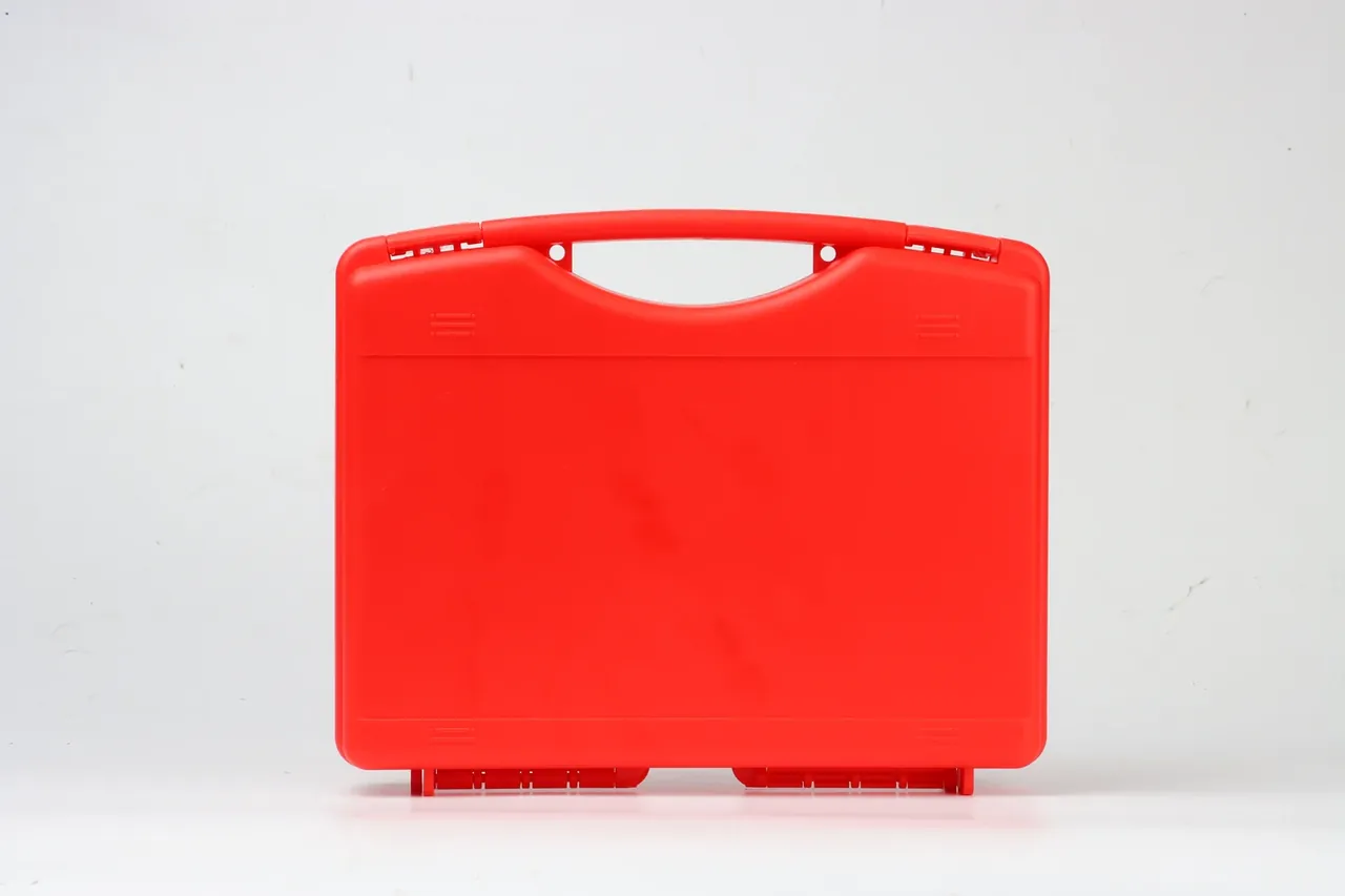
Quick answer: A MIL-STD-810H drop of 26 hits covers 8 corners, 12 edges and 6 faces once each, from the lowest point of the case to a 50 mm steel plate at 1.2 m, with cold and hot groups inserted.
Table of contents
- How the MIL-STD-810H drop sequence is distributed
- Where the height is measured and what it lands on
- Preconditioning at cold and hot extremes
- Bare case versus packaged case
- Structure and material that survive 26 hits
- What the report has to record
- FAQ
1. How the MIL-STD-810H drop sequence is distributed
The 26 hits come from Method 516.8, Procedure IV, and the logic is to strike every weak orientation once: 8 corners, 12 edges, 6 faces, which adds up to 26. A corner is where three edges meet and where wall thickness is hardest to reinforce, so corners go first; edges follow; faces come last because they tolerate impact best and will not mask an earlier corner crack.
The order is not negotiable. One specimen takes all 26 in a row, with no swap and no patch, otherwise a crack at drop 17 disappears under a repair made at drop 3. Each hit is logged and photographed only, and the case is opened after drop 26, so the sequence stays one load history rather than 26 separate tests.
| Location | Hits | Attitude | Watch |
|---|---|---|---|
| 8 corners | 8 | Corner tip down | Corner cracks |
| 12 edges | 12 | Edge leading | Dents, latch release |
| 6 faces | 6 | Face parallel | Lid sag, rib whitening |
2. Where the height is measured and what it lands on
The height of a MIL-STD-810H drop runs from the lowest point of the case to the impact surface, not from the handle or the centre of gravity, and the attitude at release decides which point is lowest. Ten millimetres of setup error is ten millimetres of lost height, and a handled case is easy to mis-measure.
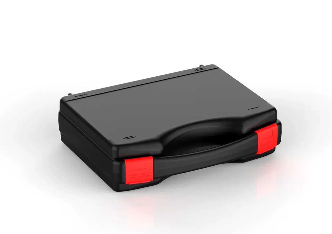
The target is not a concrete floor. It is a 50 mm steel plate on a rigid base, flat, without an elastic layer, wider than the case footprint so no corner lands off the plate. A thin plate deflects first and absorbs energy, which flatters the result.
Height to speed makes the demand concrete: 1.2 m of free fall reaches about 4.85 m/s, and a 6 kg case carries roughly 71 J into the plate. That energy has to be absorbed by plastic at the corner within milliseconds, through yielding and rib deformation. Release by hook or pneumatic rig is fine if no launch velocity is added.
3. Preconditioning at cold and hot extremes
Ambient drops alone do not close the case. The procedure calls for groups at both extremes: 4 hours at -40 °C and 4 hours at +60 °C, long enough for a 3 mm wall to soak through. A 3 mm PP section stabilises in about 2 hours, so 4 hours leaves margin.
The gap after removal decides validity. Each group is dropped within 5 minutes of leaving the chamber; beyond that the surface warms and cold behaviour is lost. The cold group still starts with corners, since notched impact strength of PP at -40 °C falls to roughly 30% of its ambient value.
The hot group fails differently. At +60 °C the modulus drops and latch engagement creeps under preload, so a tongue can slip by around drop 10, a release that ambient MIL-STD-810H drop work almost never shows.
4. Bare case versus packaged case
The two calibers measure different things. Bare-case testing treats the shell as the specimen and grades body, latches and hinges. Packaged testing drops the case inside its shipper and cushioning, grading the survival of the whole pack through a transport chain.
| Item | Bare case | Packaged |
|---|---|---|
| Specimen | Case body | Case plus cushion |
| Height | 1.2 m | Stepped by pack mass |
| Criterion | No through-crack | Cushion set intact |
The two calibers of one MIL-STD-810H drop cannot be mixed. Cushioning absorbs a large share of the energy, so bare-case corner stress can exceed twice the packaged figure, and quoting a 1.2 m pass without a caliber says nothing. Match the caliber to the shipping form, and where both are needed run the bare case first.
5. Structure and material that survive 26 hits
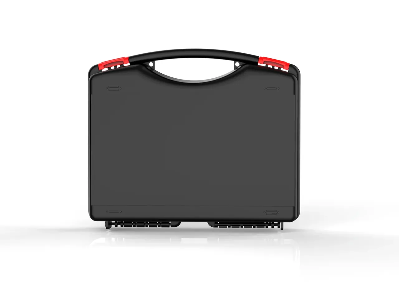
Surviving a MIL-STD-810H drop of 26 hits comes down to three dimensions: wall, radius and engagement. A 3 mm wall is the usual starting point for this class of case, and 2.5 mm tends to crack at the corner in the cold group; an R5 radius spreads stress from a line into an area; and 2.5 mm of latch engagement, a millimetre above the common 1.5 mm, cuts release visibly.
Material matters as much. Copolymer PP carries 5% to 10% ethylene blocks, giving two to three times the ambient notched impact strength of homopolymer and a wider gap at -40 °C. The weld line also has to leave the corner zone, since molecules do not entangle across it and it is the usual origin of a crack.
| Failure | Site | Answer |
|---|---|---|
| Corner crack | Base corner | R5, weld line moved out |
| Latch release | Tongue root | Engagement at 2.5 mm |
| Lid sag | Lid centre | 8 mm ribs in a grid |
Retest after any tool change, since weld line position shifts 2 mm to 3 mm between machines on the same mould.
6. What the report has to record
The first entry is the measured height, written as 1.20 m with the measurement method, never the nominal figure copied from a drawing. The second is the drop schedule: 26 rows stating which corner, edge or face, in what attitude, at what time.
The third entry covers temperature and interval, with the -40 °C and +60 °C groups listed apart. The fourth is the post-drop check within 30 minutes: through-cracks, whether latches still sit engaged, hinge looseness, then 20 open-close cycles and a pressure decay recheck inside 0.5 kPa of the pre-drop reading. The fifth is one frame per corner keyed to the schedule, plus rig number. A report with a conclusion page and no schedule counts as no test.
Conclusion
The hard part of a MIL-STD-810H drop is not the 1.2 m figure but how the 26 hits are ordered and what is inspected afterwards: 8 corners, 12 edges and 6 faces form one sequence, the -40 °C and +60 °C groups expose material limits, and the verdict rests on shell cracks, latch engagement and a pressure decay recheck. Put those into the test plan and a MIL-STD-810H drop becomes evidence rather than theatre.
This article discusses only the container (case body) side of specifications and design intent, and does not cover any handling, loading or use of the contents.
Related Reading
- Impact resistance criteria for cases
- Drop-resistant equipment case applications
- Test conditions for airdrop cases
- Injection moulding for protective cases
- Comparing case raw materials
Related Products
- 8 Series — Gun Cases; Military Equipment Cases; Camera Equipment Cases; Drone Cases; Watch Cases; Knife Cases; First Aid Cases; Electronics Equipment Cases
- WL8-2812 PP Gun Case — model WL8-2812
- All protective cases and toolboxes: 7 series, 158 models