

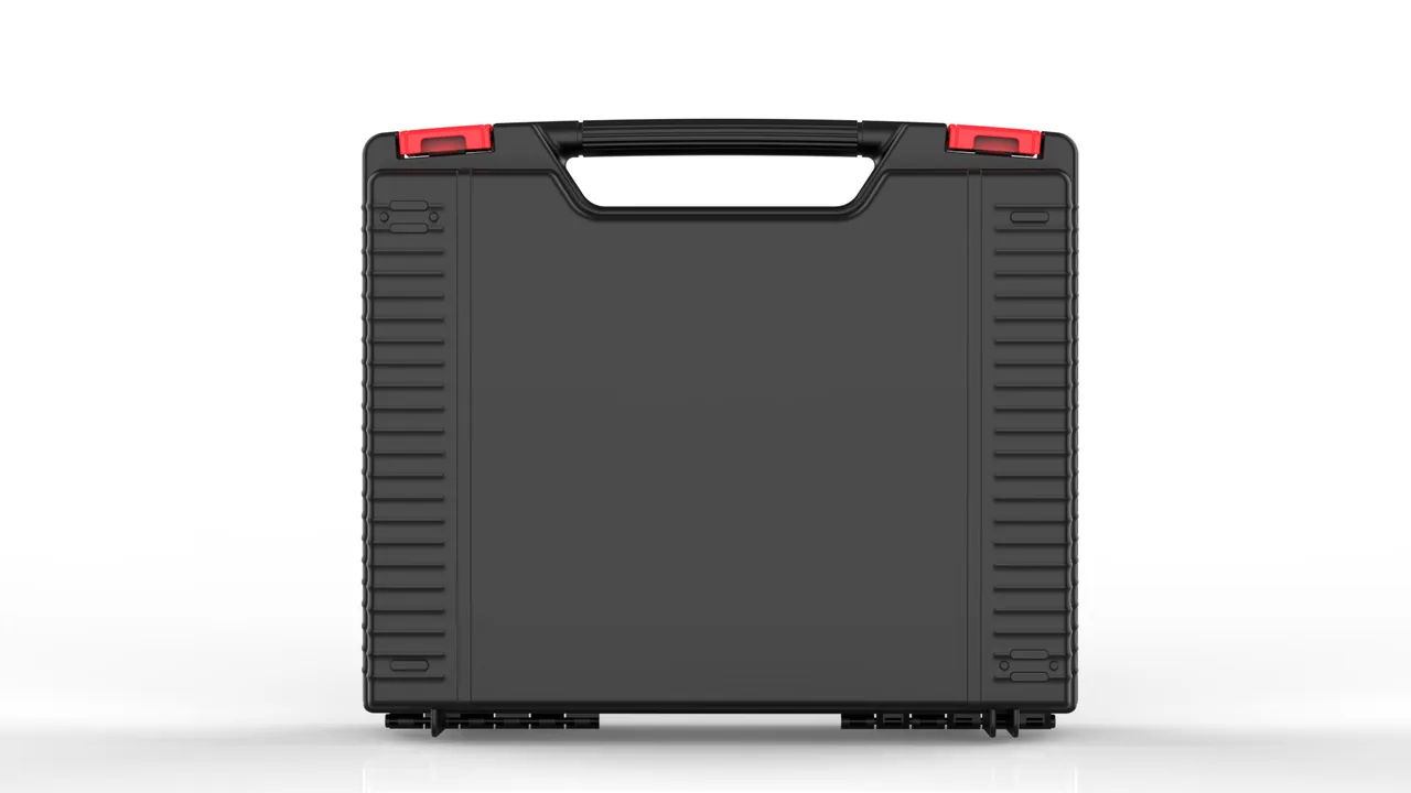
When a stator winding machine is retooled, relocated or sent back for overhaul, the hard part is never the frame. It is the small parts nobody thinks about until they are missing. A tungsten-carbide winding nozzle is barely thicker than a toothpick and its bore is a fraction of a millimetre across, so one drop onto concrete is one chipped mouth. A tensioner leaf spring works close to its elastic limit, and a cable tie cinched around the tension arm will deform it permanently. A locating dowel on a stator fixture runs with a fit clearance of one or two hundredths of a millimetre, and a single bright scratch is enough to lose that accuracy forever. These parts are usually tipped into a tote bin in the shop, yet when they fail the whole line stops for a replacement and a fresh calibration.
The protection logic for winding-machine parts is not "pack it thicker" but "cut the load path for every failure mode." Brittle parts need impact isolation, spring-loaded parts need their posture locked, precision fits need hard contact eliminated, and electrically sensitive devices need both static and moisture blocked. JUNZHIJIA starts from a part-level failure analysis, then fixes compartment dimensions, liner material, cushion stroke and sealing class, and only then designs the case structure. The sections below work through the machine part by part and can be used directly as the basis of a packing work instruction.
Table of Contents
- Brittle Fracture in Tungsten-Carbide Winding Nozzles and Compartment Design
- Preserving Tensioner Arm and Leaf-Spring Accuracy
- Preventing Damage to Stator Fixture Locating Dowels
- Mirror-Finish Protection for Ceramic Wire Eyes and Guide Rollers
- Micro-Vibration Isolation for Winding Spindles and Cam Groups
- Flatness and Hole-Position Retention on Stator Fixture Plates
- ESD and Moisture Control for Tension Sensors and Encoders
- Indexed Compartments Against Loss of Nozzles and Tensioner Small Parts
- Splitting the Stator Fixture and Weight-Grading the Load
- Isolating Enamel-Wire Debris and Grease Contamination
- Re-checking Case Sealing in a Dusty Winding Shop
- Arrival Inspection Criteria and Packing Records for Winding Parts
- Frequently Asked Questions FAQ
- Conclusion and Related Reading
Brittle Fracture in Tungsten-Carbide Winding Nozzles and Compartment Design
A winding nozzle, also called a wire guide or wire eye, is normally ground from tungsten-carbide rod with a ruby or zirconia insert at the tip, and some high-end machines use a solid carbide bore. Its hardness reaches roughly HRA 89 to 92 and its compressive strength exceeds 4000 MPa, but its transverse rupture strength is only 1500 to 2500 MPa and its fracture toughness is a mere 8 to 14 MPa·m<sup>1/2</sup>. That set of numbers describes a classic brittle material: strong in compression, weak in tension, excellent against wear, hopeless against impact.
The thinner the geometry, the worse it gets. Common shank diameters run from 0.8 to 3 mm, the wall at the exit end may be only 0.1 to 0.3 mm thick, and the bore ranges from 0.2 to 1.2 mm. Under those proportions, any combination of a point contact and a sideways force is enough to tear a corner off the mouth. A chipped edge measuring 0.02 mm sounds trivial, but it changes the wire exit angle, which shows up as pitch variation and tension spikes, and finally as poor slot fill factor and a higher rate of turn-to-turn shorts in the stator.
| Failure mode | Trigger | Packing measure |
|---|---|---|
| --- | --- | --- |
| Chipped or snapped mouth | Direct impact with hard metal or the case wall | One nozzle per compartment, wall thickness 8 mm or more, no mixed loading |
| Bore scoring or blockage | Residual enamel debris, grinding dust, fibres | Ultrasonic clean and dry, silicone cap, then a separate PE bag |
| Insert loosening | Shear load on the braze or adhesive layer | No axial compression, full circumferential wrap, bore never touching the pocket floor |
| Micro-distortion of the bore | Stacking load transferred along the case wall | At least 10 mm of free headroom above the insert, load-bearing pillars in the case |
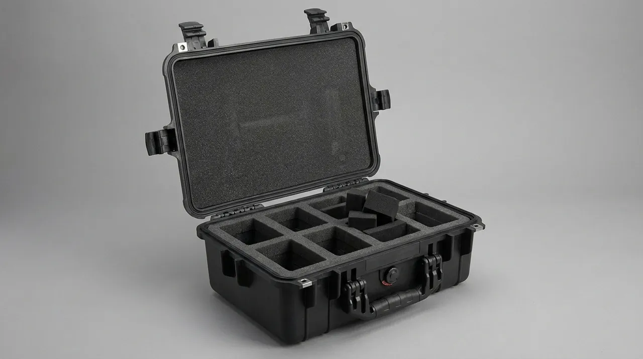
Use IXPE or thermoformed EVA for the compartment liner. The closed-cell IXPE rebounds quickly and tolerates repeated compression, which suits a returnable case, while thermoformed EVA gives an equidistant wall around the shank and a predictable cushion stroke, which suits a one-way export pack. Either way, the pocket floor should be a V or half-round cradle so the shank mid-section carries the load and the mouth stays in free air. Pointing the mouth upwards and fitting a silicone cap is the cheapest and most effective single measure available. The insert box then drops into an outer liner, giving two-stage protection, so that even a 1.2 m drop keeps local acceleration below the fracture threshold.
Posture matters as much as cushioning. Laid flat, the shank sags under its own weight and continuous micro-vibration fatigues the thinnest section. Stood vertically, the mouth takes the stacking load in the worst possible direction. The engineering compromise is a tilt of 15 to 30 degrees, which lets the liner carry most of the shank while the mouth stays clear and unloaded. That posture is easy in a thermoformed liner and needs an extra angled wedge in hand-cut foam. Comparable small-part isolation practice is described in precision instrument compartment protection.
Preserving Tensioner Arm and Leaf-Spring Accuracy
A tensioner delivers constant wire tension, typically to within 2 to 5 percent of the set value. It consists of a leaf spring or spring pack, a damper that may be magnetic hysteresis or oil type, a tension arm and a tension wheel. The leaf spring is the weak link: its working point usually sits between 60 and 80 percent of the elastic limit, and a sideways push, a mis-seated return, or the inertia of a lifting frame can all drive it past that limit.
An overloaded leaf spring does not break, it goes soft. It fails to return to zero after unloading and the whole tension curve shifts. This damage is almost impossible to spot in the shop because the spring looks intact, and only a segment-by-segment tension measurement exposes it. By then, a number of stators have usually been wound out of specification.
The fixing rule is therefore: restrain the swing of the arm, not the load on the arm. Three practices follow from it. First, use the transport block supplied with the machine, or make a POM stop, and lock the arm at the zero-tension working position so the spring sits at free length with no preload. Second, if the damper is oil-filled, confirm the reservoir orientation before locking, because a long period of tilt lets the damping oil pool on one side. Third, never strap the tension arm with a cable tie, tape or wire. A strap applies a sideways clamp that becomes a bending moment on the arm, and that moment is carried entirely by the leaf spring, which is exactly the loading that causes permanent set.
The tension wheel, whether ceramic or POM, needs the same care. Groove roughness rises with wear, and once scratched the groove acts like a file on the enamel film. Wrap the wheel so the groove touches nothing hard, and where the wheel is packaged with the arm as one module, cradle the module from below, locate it from the sides and leave at least 5 mm of free headroom above. A partition of at least 10 mm must separate adjacent modules so they cannot squeeze each other in transit.
Preventing Damage to Stator Fixture Locating Dowels
A stator fixture, also called a winding mandrel or fixture base, usually carries two to four locating dowels that mate with the fixture plate in an H7/h6 or tighter transition fit, with clearances in the 0.01 to 0.03 mm range. That clearance sets the concentricity of the stator core during winding, and therefore the uniformity of the load on the slot insulation.
Three damage patterns dominate. Mushroomed dowel heads form a small plastic lip after a knock, and the lip scores the bore during insertion, then grows into a burr within a short time. Bent dowels occur where the length-to-diameter ratio is high, typically 8 mm diameter by 60 mm long, because a side impact produces 0.05 to 0.2 mm of bend that shows up as a stiff but possible assembly. Scored bores result from copper swarf or grit entering the hole and being forced through during assembly, leaving axial scratches that destroy cylindricity.
The countermeasures are simple but must be applied to every part. Fit each dowel with a nylon or POM sleeve whose bore is 0.2 to 0.5 mm larger than the dowel, with a ball nose or chamfer at the open end, and cap the fixture-plate bores with soft plugs or protective film. Above all, pack the dowels and the plate separately rather than sliding the dowels back into their bores for transport. Re-inserting them feels safe but produces fretting corrosion between dowel and bore under vibration, which damages the mating faces more than keeping them apart.
Dressing a damaged dowel in the shop is acceptable provided the fit is recalculated. Dressing reduces the diameter and therefore changes the fit class, so a dowel that has been dressed may need to be replaced with the next oversize, or the plate may need a bush. Grinding must remove the lip around the whole circumference rather than a local high spot, and cylindricity after dressing should be held within 0.005 mm. A dowel bent by more than 0.05 mm should not be straightened, because straightening leaves residual stress that slowly relaxes in service.
Mirror-Finish Protection for Ceramic Wire Eyes and Guide Rollers
Ceramic wire eyes, made of 95 or 99 percent alumina or of zirconia, and enamel-wire guide rollers share one defining feature: the working surface is a mirror. The bore of a wire eye is typically specified at Ra 0.2 micrometre or better, and roller grooves sit in the same range. That surface runs against enamel wire travelling at 3 to 20 m/s, so any scratch becomes the starting point of three-body abrasive wear and can cut through the enamel film within a few thousand metres of wire.
The mirror-finish packing rule is absolute: never put these parts in the same compartment as metal components. Even with a foam layer between them, a metal part will migrate under vibration, thinning the foam until hard contact forms. The correct approach is as follows.
| Part | Lining method | Prohibited |
|---|---|---|
| --- | --- | --- |
| Loose ceramic eyes | Wrap in non-woven cloth, single pocket with flocked inner face | Sharing a pocket with bearings, bolts or dowels |
| Eyes already fitted to nozzles | Pack with the nozzle in one pocket, silicone cap on the exit | Exit face resting on the pocket floor |
| Guide rollers | V-groove cradle plus axle location, groove in free air | Using the groove as a locating surface |
| Traverse ceramic tubes | One tube per pocket with end collars | Long tube supported only at the ends, bowing in the middle |
Non-woven wrapping also provides a soft electrostatic barrier. Enamel wire accumulates static charge while winding, and dust near the ceramic eye becomes charged and clings to the mirror surface, creating a fresh source of abrasive particles. Clean mirror parts with ionised air or an antistatic brush before packing, and avoid wiping them with ordinary cotton cloth, because the short fibres are themselves a contaminant.
Micro-Vibration Isolation for Winding Spindles and Cam Groups
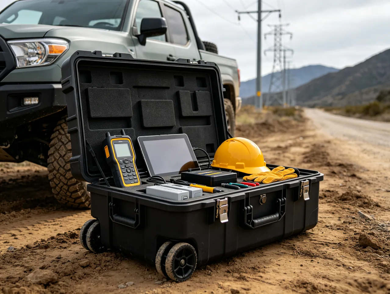
A winding spindle normally runs on precision angular-contact ball bearings in a preloaded pair, with radial runout held to 3 to 8 micrometres, while a cam group of conjugate cams and roller followers sets the traverse pitch through its phase accuracy. The risk in transit is not a single hard knock but slow accumulation of damage from low-frequency micro-vibration, which produces false brinelling, alters preload, and later appears as higher vibration and uneven traverse pattern.
Isolation works on three levels. Choose support points near the bearing journals rather than at the shaft ends, because a shorter overhang raises the natural frequency away from the low-frequency range of road vibration. Allow the shaft to remain free to rotate slowly rather than locking it rigidly, since a fully locked shaft concentrates impact on a single rolling element while slow rotation spreads the load across several. Finally, fit a mechanical shock indicator in the case, typically set at 5 g or 10 g, so the indicator can be read before the case is opened. A triggered indicator does not prove damage, but it does mean radial runout must be measured.
The cam group needs the opposite treatment. Lock the cams at a fixed phase with a stop so the roller followers cannot lift off the cam profile and hammer back onto it under vibration. Make the stop from POM or nylon and shape its contact face to follow the cam profile roughly, so the load is not applied at a single point.
Flatness and Hole-Position Retention on Stator Fixture Plates
Stator fixture plates are usually 10 to 30 mm thick, in aluminium or cast iron, with a flatness requirement often stated as 0.02 mm per 300 mm. Their characteristic failure mode is self-weight deflection. Laid horizontally on only two or three supports, the plate bows elastically at mid-span, and although nothing is visible at first, the final fit tolerances drift after a long journey.
Control the support spacing instead of adding mass. Keep the spacing below twenty times the plate thickness, and arrange any three supports so their triangle covers as much of the plate as possible. A 20 mm plate therefore wants supports no more than 400 mm apart, so a one-metre fixture plate needs at least three rows. Use an engineering plastic softer than aluminium, such as POM, nylon or polyurethane, so the plate face is not indented.
Hole retention is the other dimension. Once foreign matter enters a dowel bore, bolt hole or wire passage, assembly jams and the operator taps the part, which mushrooms the hole edge. Blow every through-hole clear and plug it before packing. Plugs on an upward-facing surface should sit below the plate face so they cannot become load points. Where plates must be stacked, separate them with equal-height blocks of at least 30 mm, positioned to avoid the holes.
Standing a plate on edge is an option, but a plate with a tight flatness callout is better supported flat at several points, because an edge-standing plate takes side squeeze. If case height forces an upright posture, lean the plate at 10 to 15 degrees from vertical on an angled cradle so it is held by its own weight rather than by clamping force.
ESD and Moisture Control for Tension Sensors and Encoders
Tension sensors are usually strain-gauge or micro-displacement types with millivolt outputs, and encoders emit pulse trains, so both are sensitive to electromagnetic interference and electrostatic discharge. Two damage paths matter at the packing stage. Electrostatic discharge can reach several thousand volts when plastic foam rubs in dry conditions, and direct contact with a signal terminal can puncture the gate of an input MOSFET. Such damage is latent, invisible at dispatch, and appears as zero drift weeks after installation. Moisture and condensation oxidise sensor connectors and encoder scale discs, and contamination of the scale disc causes dropped pulses.
The packing requirements follow directly. Use antistatic foam with a surface resistance of 10<sup>4</sup> to 10<sup>6</sup> ohm together with antistatic shielding bags. Keep the sensor body apart from its cable and coil the cable to no tighter than its minimum bend radius, usually five times the outer diameter. Add desiccant, silica gel or molecular sieve, at about 20 g per cubic metre of free space, and include a humidity indicator card with 40, 50 and 60 percent thresholds.
Where the case itself is plastic, consider a grounding terminal on the body, or a conductive-filled shell, so that an operator can discharge before opening. In dry regions where relative humidity stays below 35 percent all year, that measure is extremely valuable and costs almost nothing. Related limits for electrically sensitive assemblies are set out in ESD component case design.
Indexed Compartments Against Loss of Nozzles and Tensioner Small Parts
A multi-axis winding machine commonly uses 20 to 60 winding nozzles and 8 to 24 tensioners, plus more than a hundred small parts including leaf springs, ceramic eyes, shims and circlips. The dominant risk for this class of part is not damage but loss and mismatch. Tensioner leaf springs are used in matched sets, so mixing them corrupts the tension curve, and nozzles are grouped by wire diameter, so swapping groups raises the breakage rate immediately.
Indexed storage is the low-cost, high-return answer, and it rests on three elements. Give every part its own pocket, with the pocket number matching the machine station number, such as A1 or A2, printed on the foam surface and covered with clear tape so repeated use does not wear it away. Mark unused pockets with a high-visibility plug, red for example, so a missing part is obvious both at closing and at opening. Attach a pocket list to the inside of the lid showing part number, quantity, specification in terms of wire diameter or tension range, packer and date, laminated or sleeved so it can be replaced on a returnable case.
For very small parts such as circlips, shims and pins, cutting individual pockets is impractical. Use a two-level arrangement: place like parts in a lidded miniature compartment box, then treat that box as a single item in the main compartment layout. It costs a little volume and returns full traceability with no losses.
Splitting the Stator Fixture and Weight-Grading the Load
Stator fixture weights vary widely: a small fixture weighs 5 to 15 kg, while a fixture for a traction motor stator can reach 40 to 120 kg. Weight grading exists to fix the handling method and the stacking level, and to define the load path at the case design stage.
| Unit weight | Handling | Position in case | Case requirement |
|---|---|---|---|
| --- | --- | --- | --- |
| Under 15 kg | Manual | Upper or middle layer | Standard ribs, pallet optional |
| 15 to 40 kg | Two-person or small hoist | Middle layer over a load beam | Steel frame or heavy aluminium profile |
| 40 to 80 kg | Hoist with lifting points | Bottom layer, four-point marking | Internal lifting beams and base plate |
| Over 80 kg | Forklift or crane | Bottom layer on its own skid | Independent base, lifting beams, no-stacking label |
Splitting the assembly is an overlooked lever. Removing the detachable parts, such as clamp plates, stops, grippers and sensor brackets, and packing them separately usually lowers the centre of gravity, regularises the outline and cuts total volume by 15 to 30 percent. The trade-off is reassembly and recalibration on arrival, so decide by comparing assembly labour against transit damage risk.
Detached parts need pairing marks. Tag parts from the same fixture with the same colour label or number so that several fixtures can be packed together without cross-fitting. Where a detached part mates with its own seat, such as a gripper and its gripper base, bag the pair together and record the pairing.
Isolating Enamel-Wire Debris and Grease Contamination
The floor and equipment in a winding shop always carry copper swarf, enamel flakes and various greases. The damage these do inside a case is systematically underestimated. Copper swarf is conductive, so once it reaches an electrical chamber it can create creepage paths between terminals. Enamel flakes are insulating but hold static charge, so they cling to ceramic eye surfaces and become abrasive particles. Grease and oil mist swell foam slowly, destroy its resilience and defeat antislip surfaces.
The rule is clean first, isolate second, close last. Wash parts before packing, using anhydrous ethanol or a dedicated cleaner for metal items and ultrasonic cleaning with deionised water rinse for ceramic parts, then dry thoroughly. Keep clean parts in a separate container from uncleaned ones, and never lay liner material on the shop floor before closing the case.
Liner material must also resist oil. EPE foam is sensitive to mineral oil and grease and will shrink and collapse on prolonged contact; IXPE and EVA perform clearly better; PU foam resists oil but hydrolyses in humid conditions and crumbles. For winding-machine parts in a returnable case, specify IXPE. For a one-way export pack, EVA is acceptable. Avoid putting plain EPE foam directly against any greased or oiled part. If a part must ship with oil on it, bag it in PE first, then place it in the EVA pocket.
Case cleanliness is part of the same discipline. Foam crumbs, paper dust and cut strap ends are common free particles that bounce around in transit and strike mirror surfaces. Vacuum or blow out the case with clean compressed air after packing and before closing, then do the final count.
Re-checking Case Sealing in a Dusty Winding Shop
The winding shop is not a controlled environment. It carries dust, copper powder, enamel particles, fibre, oil mist, and summer heat with high humidity. Where a case is stored in the shop before dispatch, the sealing class should be chosen from residence time times environment severity rather than habit.
For short storage under one month before shipment, IP54 to IP55 covers dust and splash. For storage beyond three months, or for sea freight, specify IP65 or better with a pressure equalisation valve. For sea freight, or for routes crossing climate zones such as southern China to the northeast or an export shipment to Southeast Asia, a pressure equalisation valve and desiccant are mandatory, because the pressure differential from day-night temperature swings repeatedly loads the lid seal and accelerates ageing.
Sealing classes are defined by IEC 60529 and GB/T 4208. Do not accept a supplier declaration alone. Ask for a test report, or retest on a sample: a 12.5 mm/min water jet for three minutes for IPX5, and immersion at 2 m for thirty minutes for IPX7, both according to the product specification.
A pressure equalisation valve lets the case breathe as temperature and altitude change while keeping liquid water and dust out. Distinguish microporous vent membranes, which are cheap with a low flow rate, from mechanical valves with protective caps, which flow much more and suit large cases on routes with steep temperature swings. Size the valve from case free volume and expected temperature differential. An undersized valve leaves a residual differential, while an oversized one keeps the seal near its opening threshold and admits dust. The mechanism is explained further in case pressure equalization valve, and the stiffness-versus-corrosion trade-off in shell material appears in aluminium versus stainless steel toolboxes.
Arrival Inspection Criteria and Packing Records for Winding Parts
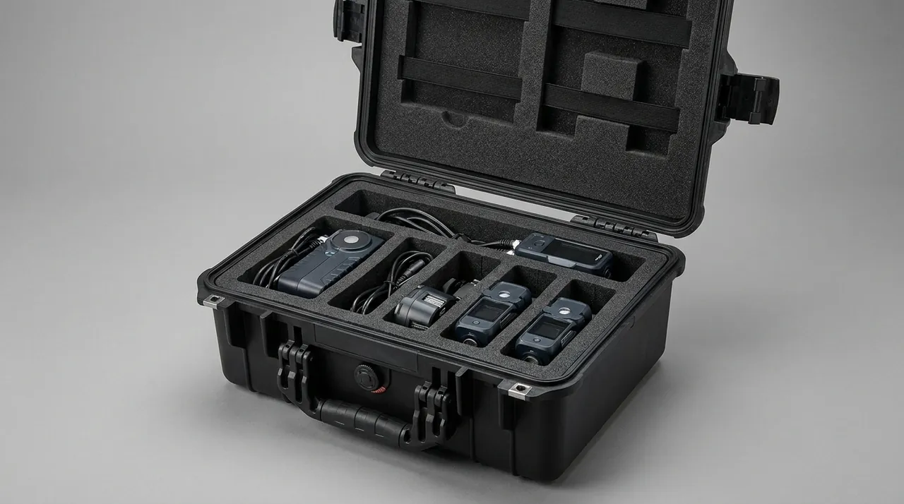
The purpose of arrival inspection is to separate transport liability from assembly liability. Without a record, every accuracy complaint becomes an argument. Work in three stages: appearance first, then accuracy, then function.
Stage one, appearance, within thirty minutes of opening: check the case for distortion, the seal for displacement, the shock indicator for triggering and the desiccant for colour change, and photograph everything with the case number and a timestamp in frame.
Stage two, accuracy, once appearance is clear: measure the critical parameters part by part. Use a profile projector or vision measuring system for nozzle bore and edge chipping, a micrometer for dowel diameter and cylindricity, a granite table with a dial gauge for plate flatness, and a tension meter for the tensioner curve and zero position.
Stage three, function, after all re-measurement passes: run ten percent of the nozzles on a machine for thirty minutes and watch the breakage rate and traverse quality, and cycle each tensioner through full travel to confirm there is no sticking.
| Part | Check item | Acceptance criterion |
|---|---|---|
| --- | --- | --- |
| Winding nozzle | Edge chipping | No visible chip, bore passes the go/no-go gauge |
| Locating dowel | Diameter, straightness | Within the h6 band, straightness 0.02 mm per 100 mm or better |
| Fixture plate | Flatness | 0.02 mm per 300 mm or better, or as drawing |
| Tensioner | Tension deviation | Within 5 percent of set value, zero drift 2 percent or less |
| Case | Seal, valve | No permanent set, valve breathes freely |
A packing record should carry the case number, packing date, packer, pocket list, serial numbers of critical parts, desiccant and indicator card batch numbers, shock indicator type and threshold, and the transport mode with expected duration. That record is both a quality trace and the input to the next packing revision. Any pocket that has produced a problem should get thicker foam or a stiffer partition next time. Broader practice for fixture-class precision parts is covered in machine toolholder transport protection.
Frequently Asked Questions FAQ
Q: Why can a winding nozzle not share a compartment with metal parts?
A: Because tungsten carbide is brittle, and its failure criterion is fracture rather than deformation. Metal parts migrate laterally under vibration, and once the foam between them has been compressed repeatedly and thinned to one or two millimetres, hard contact forms against the nozzle shank. At that point even one g of acceleration is enough to tear a corner from the mouth. The correct practice is one nozzle per compartment with at least 8 mm of wall between pockets, a V or half-round cradle at the floor so the shank mid-section carries the load, and the mouth left in free air under a silicone cap. Where volume forces a mixed load, at least separate metal parts and nozzles into upper and lower layers with a rigid partition of 10 mm or more, and locate the metal parts individually so they cannot slide inside the case. During counting, if any nozzle can move more than 2 mm within its pocket, re-measure the pocket and replace the liner instead of filling the gap with paper.
Q: How should tensioner accuracy be verified after transport?
A: Work through three steps. First check the zero position: set tension to zero and watch whether the arm returns naturally to the mechanical zero, because a slow or offset return means the leaf spring has been overloaded. Second, plot a multi-point tension curve: measure actual tension at 30, 60 and 100 percent of the set value and compare with the factory calibration curve, where a deviation beyond 5 percent is a rejection. Third, check dynamic response: run at the normal line speed for five minutes and record the tension fluctuation band, since a band more than 50 percent wider than the factory value usually means the damper or the tension wheel groove is damaged. The tension meter used must be within its calibration period, the measuring point must be fixed at the same position at the tension wheel exit, and three readings should be averaged. If any step fails, do not adjust the spring preload screw on site to force the number back into range, because that hides the defect until volume production. Send the unit back for calibration or replace the spring pack instead.
Q: Can a locating dowel that has been nicked be dressed and reused?
A: It can be dressed, but the fit must be recalculated and the dowel must not simply be pushed back into place. Dowels mate in an interference or tight transition fit, so removing 0.01 mm of diameter changes the fit class and can allow the fixture to creep after assembly, which then affects stator concentricity. Dressing should remove the lip uniformly around the circumference with an oilstone or fine abrasive paper rather than grinding one high spot, and the result should be verified with a micrometer taken in two mutually perpendicular directions at the same cross-section, holding cylindricity within 0.005 mm. After dressing, re-measure the diameter; if it falls outside the original fit band, move to the next oversize dowel or fit a bush in the plate. Do not straighten a dowel bent by more than 0.05 mm, because straightening introduces residual stress that slowly relaxes in service. Check the plate bores as well: measure cylindricity with an internal micrometer, and where axial scoring is present, ream lightly and match a new dowel to the reamed bore.
Q: Which liner should be used: IXPE, EVA or plain PE foam?
A: Choose by service pattern. For a returnable case used more than twenty times, IXPE is the first choice: it is closed-cell, rebounds strongly and resists repeated compression, typically showing less than 5 percent compression set at 25 percent compression, and its oil resistance is better than EPE. For one-way factory packing, thermoformed EVA is preferable because it can be moulded to an equidistant wall around a nozzle shank or a fixture contour, the cushion stroke can be calculated, and the insert locates parts cleanly. Plain EPE foam is the cheapest option, but it rebounds slowly, resists oil poorly and loses thickness noticeably under sustained load, so it belongs in the outer cushioning layer rather than against a precision part. If a part ships with oil or grease on it, EPE will shrink and collapse, so bag the part in PE before it goes into the pocket. Density matters too: IXPE is commonly 33 to 45 kg per cubic metre and EVA 60 to 80, and higher density carries more load but shortens the cushion stroke, so brittle parts need stroke rather than stiffness.
Q: How should nozzle bores be cleaned, and how is rust prevented afterwards?
A: Tungsten carbide itself does not rust, but the brazed copper layer, the adhesive layer and the steel nozzle seats on some models do. Clean by blowing compressed air backwards from the exit end to push debris out of the bore, then ultrasonic cleaning in anhydrous ethanol or a dedicated cleaner for three to five minutes at about 40 kHz, avoiding strong alkali or acid which attack the braze and adhesive. Rinse with deionised water, blow dry with compressed air, then dry in an oven at 60 to 80 degrees Celsius for thirty minutes so no liquid remains in the bore. For rust prevention, treat the steel seat and the braze layer only, with a thin film of rust-preventive oil or a volatile corrosion inhibitor, then cap the mouth and bag each nozzle separately. Do not oil the bore itself, because the film attracts dust and turns into sludge at high wire speed, which contaminates the enamel wire directly. After cleaning, sample the bores with the matching go/no-go gauge for wire diameter, and log the cleaning batch and oven temperature profile in the packing record.
Q: How is the temperature and humidity inside the case controlled?
A: Fix the target first, then the means. For winding-machine parts the usual target is a relative humidity of 60 percent or below with no condensation on any part. Three layers deliver it. Sealing comes first: use a case rated IP65 or better to IEC 60529 and GB/T 4208 with a pressure equalisation valve, which blocks convective moisture transfer. Desiccant comes second: allow about 20 g of silica gel or molecular sieve per cubic metre of free volume, and include a humidity indicator card, normally with 40, 50 and 60 percent thresholds. Thermal buffering is third and can be omitted for temperature-insensitive parts, though on routes with day-night swings above 20 degrees, adding 10 mm of insulating blanket to the case wall clearly reduces condensation risk. Remember that a sealed case cannot purge moisture by itself, so once packing introduces damp air, for example on a rainy day or with a part that was not fully dry, humidity rises quickly once the desiccant is exhausted. Pack indoors during the rainy season, dry every part completely, and put the desiccant in at the last moment before closing.
Q: Can the case be used repeatedly, and what must be checked each time?
A: Yes, provided the shell is sound and the liner can be renewed completely. Five checks are worth making before each reuse. Inspect the seal for permanent set, crazing or displacement from its groove, since a light press with a fingernail should spring back. Confirm the pressure equalisation valve still breathes, using a differential pressure method or a simple listening check. Examine latches and hinges for cracks, because plastic parts develop internal micro-cracks after repeated impacts that are hard to see, so replace them on a fixed cycle. Look for bulging, punctures or embedded debris on the inner walls. Finally, measure compression set on a test block of the nominal foam thickness and renew the whole liner beyond 30 percent rather than replacing it in patches. If the case has previously carried oiled or corrosive parts, clean it thoroughly and inspect the hardware for corrosion. Adding a QR asset label that links turnover count, liner replacement history and transport exceptions to one case number is the simplest way to move from judgement to data.
Q: What should be done if the case seal is found flattened or distorted on arrival?
A: First decide whether the deformation is elastic or permanent. Remove the seal, lay it on a flat surface and leave it for two hours; if the cross-section recovers, the seal can be cleaned and re-seated in its groove. If it stays flattened, compression set has occurred and the whole seal must be replaced rather than repaired locally. Three points matter when replacing it: the material and hardness should match the original, commonly silicone at 40 to 60 Shore A or EPDM; the cross-section must match the groove width and depth; and the joint should be a scarf-cut butt joint with the correct adhesive, positioned at the middle of a short side rather than at a corner. After replacement, run a simple re-test by placing a humidity indicator card inside, closing the case and subjecting it to spray or immersion, then checking whether the card changes colour. If the seal is deformed and the shell is also visibly dented or warped, the case has taken an over-limit impact, so inspect the whole structure and withdraw it from service.
Conclusion and Related Reading
Winding-part protection maps service accuracy onto transit constraints: fracture limits, elastic limits, fit clearances and static thresholds become compartment sizes, liners and sealing classes. JUNZHIJIA builds custom liner and case solutions.
Related Reading