

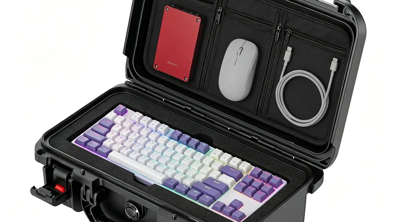
Precision instruments used in nuclear facilities rarely fail the way outsiders expect. A dose-rate meter does not stop working because radiation passed through its case, and an aerosol sampler is seldom defeated by its detector. More often the chain starts with a wipe-down in a decontamination room: the exterior coating lifts, abrasive grit carried by the cloth scores the sealing face, the compressed gasket can no longer fill the groove, and radioactive dust migrates into the cavity. Once there it settles on optical windows and connectors and slowly raises background counts.
JUNZHIJIA takes a firm position on this category: a protective case provides no shielding function and should never be marketed as a radiation barrier. Its job is to keep the instrument structurally intact, keep its surfaces cleanable, keep contamination out of the cavity, and let operators open, close and lift the case without standing next to it. Turning those four promises into measurable acceptance criteria is worth far more than any claim printed on a nameplate.
Table of Contents
- 1. Storage and Transport Constraints for Nuclear Instrumentation
- 2. How the Radiation Field Actually Affects Case Materials and Seals
- 3. Shell Selection: Stainless Steel, Polypropylene, Polyethylene and Hybrids
- 4. Sealing Classes: What IP65 and IP67 Really Require
- 5. Seal Materials and Dose-Rate-Related Aging
- 6. Decontamination-Friendly Surfaces and Contamination Control
- 7. Suppressing Ingress of Radioactive Dust and Particulate
- 8. Remote-Handling Geometry and Mechanical Interfaces
- 9. Liner Compartments and Securing Precision Instruments
- 10. Clean-Zone and Dirty-Zone Logistics with Status Marking
- 11. Transport Profiles: ISTA, GB/T 4857 and Stacking Load
- 12. Quality Control, Documentation and Acceptance Hold Points
- Frequently Asked Questions FAQ
- Conclusion and Related Reading
1. Storage and Transport Constraints for Nuclear Instrumentation
A general-purpose instrument case assumes three things: a person stands beside it, the environment is clean, and damage can be repaired later. Inside a controlled area all three assumptions collapse at once. Staff work under dose and time limits and cannot linger next to an open case. Surfaces may carry transferable contamination, so any opening action risks dragging contamination inward. And once an instrument is contaminated, cleaning it costs far more than the case itself, while the cleaning process is exactly when delicate parts are most likely to be harmed.
The failure chain generally runs like this. Repeated wiping with decontamination fluid blisters the coating locally, and the exposed substrate becomes a particle trap. Grit trapped in the cloth scores fine grooves across the sealing face, and the compressed gasket can no longer bridge them. When temperature swings or transfer through a pressure gradient make the case breathe, the equalisation valve draws outside air along with particles clinging to the exterior wall. Those particles land on connectors and optical windows and become fixed contamination that wiping cannot remove. Not one step in that sequence involves radiation penetrating the case wall; every step is mechanical or environmental, which is why the specification must translate site constraints into design responses.
| Site constraint | Case design response | Recommended verifiable criterion |
|---|---|---|
| --- | --- | --- |
| Repeated wiping with decontamination fluid | Non-porous shell, continuous welds, chemical-resistant finish | No blistering after a defined wipe cycle |
| Alpha and beta particulate on surfaces | Generous radii, minimal seams, replaceable gasket | Defined upper limit on internal roughness |
| Staff cannot work close to the case | External lifting points, extended handles, tool-free closure | Control of lifting-point offset from the centre of gravity |
| Exterior contamination is unavoidable | Separation of exterior and cavity, replaceable seals | Gasket replacement leaves the shell undamaged |
| Instruments cannot be cleaned in place | No wall contact, liner removable as one piece | Liner lifts out without tools |
Such a table converts a vague requirement such as "contamination resistant" into clauses covering material, geometry and testing. Any requirement that cannot be reduced to a criterion becomes an argument at goods-in inspection.
2. How the Radiation Field Actually Affects Case Materials and Seals
One misconception deserves clearing up first. Radiation tolerance of a case material means the ability to retain mechanical properties after absorbing a cumulative dose; it has nothing to do with whether the material attenuates gamma or neutron radiation. In polymers, cross-linking and chain scission compete. Polyethylene tends to cross-link at moderate doses, becoming stiffer and slightly more brittle. Polypropylene, with its tertiary carbon structure, is far more prone to chain scission, so tensile strength and elongation at break fall while the brittle transition temperature rises. Elastomers behave differently again: the practical symptom is increasing compression set and declining rebound, meaning a gasket under long-term compression gradually forgets the shape it should recover.
Temperature, oxygen and ozone accelerate all of these processes. A case may sit at ambient temperature for months, be sprayed in a humid decontamination bay, then be loaded outdoors in winter, so seal aging combines radiation, thermo-oxidative stress and mechanical fatigue rather than dose rate alone. A workable approach screens materials against three variables at once — cumulative dose band, service temperature and chemical exposure — and then treats the seal as a consumable.
| Elastomer or polymer | Relative radiation tolerance (qualitative) | Dominant aging symptom | Trade-off in case design |
|---|---|---|---|
| --- | --- | --- | --- |
| EPDM | Moderate to good | Rising compression set, slow rebound loss | Good value for replaceable gaskets |
| Silicone (VMQ) | Good | Deforms under long compression, stays flexible when cold | Preferred for wide temperature range |
| FKM | Good | Excellent chemical resistance, poor cold elasticity | Use where decontamination fluids are aggressive |
| Polypropylene | Fair | Chain scission, embrittlement, colour shift | Easy to mould, cumulative dose must be controlled |
| HDPE | Good | Cross-links, hardens yet keeps toughness | Common for rotomoulded shells |
These ratings are a screening aid only; two compounds of the same family can behave very differently depending on filler loading, antioxidant package and cure system.
3. Shell Selection: Stainless Steel, Polypropylene, Polyethylene and Hybrids
The shell decides whether a case can be decontaminated repeatedly and whether it can be repaired after impact. The most underestimated cost in controlled areas is not the purchase price but how much labour one decontamination consumes and how many cycles the shell survives. Stainless steel wins on that measure: its surface tolerates solvents, alkaline cleaners and low-pressure steam, and after grinding and passivation the welds present no adsorptive micro-porosity. The penalties are mass and thermal conductivity, since a cold outdoor transfer condenses moisture on the interior wall.
Polypropylene and polyethylene take the opposite route. They mould easily, cost less per unit and absorb impact well, and they can be formed with integral ribs and compartments. Against them sit surface adsorption and static charge, both of which encourage particulate to cling, plus a tendency to acquire hazy scratches during mechanical wiping. A hybrid design captures the strengths of both: a structural frame or rotomoulded outer shell carries impact and stacking loads, while a thin stainless or dense-plastic inner liner provides the cleanable surface.
| Option | Typical wall thickness | Decontamination suitability | Impact resistance | Mass | Repairability | Typical use |
|---|---|---|---|---|---|---|
| --- | --- | --- | --- | --- | --- | --- |
| 304/316L folded and welded steel | 1.2–2.0 mm | Excellent | Moderate (dents easily) | High | Local weld repair | High-frequency decontamination |
| Rotomoulded LLDPE monocoque | 4–8 mm | Moderate | Excellent | Medium | Difficult; usually replaced whole | Frequent transfer, lifting impacts |
| Injection-moulded PP with ribs | 2.5–4 mm | Fair to poor | Fair to poor | Low | Difficult | Light instruments, indoor use |
| Frame plus stainless inner liner | Structure-dependent | Excellent | Excellent | High | Liner replaceable separately | High-value, long-life instruments |
Three questions normally settle the choice before any datasheet is consulted. How many decontamination cycles will the case see over its life? What is the largest single drop height and the maximum stacking tier count? If the liner is contaminated, is the whole case scrapped or is the liner replaceable?
4. Sealing Classes: What IP65 and IP67 Really Require
Ingress protection is defined by IEC 60529 and the equivalent GB/T 4208, with the first digit covering solid objects and the second covering water; the logic behind the scale is explained in this comparison of IP65, IP66 and IP67 ratings. IP65 pairs level 6 dust protection with level 5 protection against water jets. IP67 pairs level 6 with level 7 protection against short-term immersion. For nuclear instrument cases the first digit matters most, because radioactive particulate is typically fine and level 6 demands complete dust-tightness; that is the floor for cavity contamination control. Water rating depends on whether the site actually washes equipment down. Where a case only faces rain, snow and damp air, a level 5 jet rating is sufficient. Where a low-pressure hose or brief immersion is possible, level 7 must cover it.
IP67 does not mean unlimited depth or duration. The standard immersion test specifies a defined depth and time, and anything beyond those conditions needs separate verification. A second detail is easily missed: on a case fitted with a pressure equalisation valve, dust-tightness depends on the filtration rating of the hydrophobic membrane inside that valve. The valve must be specified and verified as its own component, because it does not inherit the enclosure rating automatically.
| Rating | Dust | Water | Standard test condition | Suitable site conditions |
|---|---|---|---|---|
| --- | --- | --- | --- | --- |
| IP54 | Level 5, limited ingress | Level 4, splashing | Splash from all directions | Dry indoor zones, short handling |
| IP65 | Level 6, dust-tight | Level 5, water jets | Nozzle jet at defined flow and duration | Rain and snow during loading |
| IP66 | Level 6 | Level 6, powerful jets | Pressurised jets | Washdown, open storage |
| IP67 | Level 6 | Level 7, short immersion | Defined depth and time | Wash bays, brief flooding risk |
| IP68 | Level 6 | Level 8, continuous immersion | Agreed between maker and user | Must be explicitly agreed, never assumed |
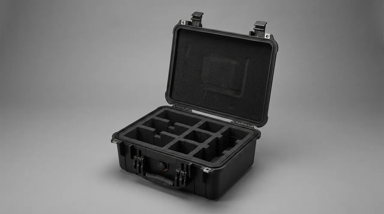
Three methods dominate: negative-pressure decay, tracer gas and direct immersion. Pressure decay suits batch release because it is fast and produces a recordable curve. Tracer gas is more sensitive and belongs in first-article and type testing. Immersion is intuitive but creates a drying burden on cases with non-removable liners. The cleanest specification names tracer gas for type testing and pressure decay for routine release, and states the pass threshold and hold time.
5. Seal Materials and Dose-Rate-Related Aging
Gaskets usually outlive neither the case nor the instrument, and it is better to admit that at the design stage by making the seal a replaceable part. Compression set is the most direct indicator of seal condition and can be measured by holding a specimen at a defined compression ratio and temperature, then recording recovery. A widely used service criterion is to replace the gasket once compression set exceeds 30 percent of the initial compression, or when the free section height recovers to less than 85 percent of nominal. Different base polymers tolerate this differently, as this guide to case seal materials explains.
A practical design window keeps the compression ratio between 20 and 30 percent. Below that range the seal cannot fill surface micro-grooves; above it, permanent set accelerates and opening force climbs. Groove width should slightly exceed the seal cross-section so the material can expand laterally, while groove depth sets the compression and must carry a drawing tolerance rather than a nominal figure. For sites with prolonged humidity or immersion in decontamination fluid, silicone is preferred for low-temperature flexibility, or FKM where chemical resistance dominates, though FKM noticeably increases opening force in cold weather.
| Seal style | Section and compression | Replacement criterion | Notes during replacement |
|---|---|---|---|
| --- | --- | --- | --- |
| Rectangular cord in groove | 20–30 percent compression | Section recovers below 85 percent | Clean the groove; grind out scores first |
| O-ring | 20–25 percent compression | Surface cracking, marked hardening | Avoid stretch installation, allow to settle |
| Foamed silicone cord | 30–40 percent compression | Slow rebound, surface chalking | Suits wide-tolerance faces |
| Foamed-in-place seal | Set by tooling | Local debonding or adhesion loss | Poor serviceability; reface completely |
Dose rate influences seals gradually. A low dose rate sustained over a long period, combined with temperatures above ambient, often accumulates more oxidative aging than a short high-dose exposure, because oxygen has time to diffuse into the material. Seal life should therefore be estimated from long-duration data close to the real duty rather than extrapolated from a short high-rate test.
6. Decontamination-Friendly Surfaces and Contamination Control
Surface engineering is the most practically valuable part of this exercise. Machined or rolled surfaces should be held to a roughness of Ra 1.6 micrometres or better. Welds must be continuous, dressed flush and passivated, with internal corner radii of at least 3 mm so that no sharp transition sits beyond the reach of a wipe. Blasted, brushed and porous powder-coated finishes look attractive but measurably raise the chance that particulate remains behind; they do not belong in controlled areas. On coatings, a thin dense epoxy or polyurethane system outperforms a thick powder film, because dense beats thick.
Labels and nameplates belong to the same discipline. Paper, fabric and foam-backed labels absorb water, lift at the edges and leave adhesive residue, and that residue is itself a particle trap. An etched stainless nameplate in a recessed holder, with a separate slotted card for variable data, lets the operator update information without touching the plate. Anything that must remain legible should survive a full immersion wash.
| Location | Recommended practice | Practice to avoid | Reason |
|---|---|---|---|
| --- | --- | --- | --- |
| Cavity wall | Ra 1.6 micrometres or finer, radiused transitions | Blasting, brushing, coarse cast finish | Rough surfaces hold particulate |
| Welds | Continuous, dressed, passivated | Stitch welding, lap joints, spatter | Crevices become fixed contamination |
| Coating | Thin and dense, adhesion first | Thick porous films | Blistering exposes a particle trap |
| Marking | Etched plate plus replaceable card | Paper labels, foam adhesive | Lifting edges leave residue |
| Drains and blind holes | No blind holes; sealable drain if needed | Upward-facing counterbores | Trapped liquid and dust cannot escape |
Chemical compatibility should be listed in the specification. Neutral detergents, mildly alkaline cleaners and alcohols are the normal set. Strong acids and chlorinated solvents are not advisable for long-term use because they attack both the passive film on stainless steel and the elastomer. Where unavoidable, neutralisation and rinsing must be defined, and verification should include a check for seal swelling.
7. Suppressing Ingress of Radioactive Dust and Particulate
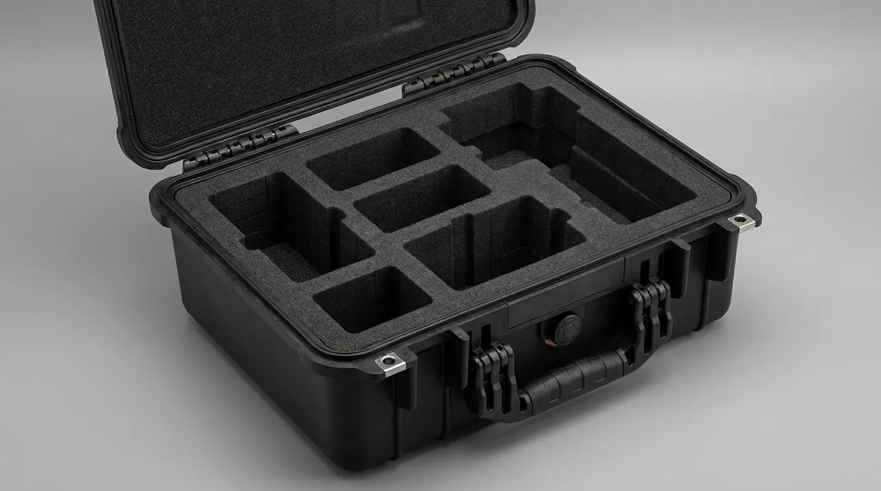
Particulate control is best organised as three barriers. The first is the shell seal and surface quality, which stop particles from settling and from passing through. The second is the liner envelope, which fills the gap between instrument and wall so that anything entering the cavity stops at the liner surface, which can be withdrawn, washed or replaced as a whole. The third is the instrument's own soft wrap, acting as final isolation and cushioning. With all three in place, a single barrier failure still leaves a usable operating window rather than an immediate contamination event.
The pressure equalisation valve is the weakest link in that chain. Cases in controlled areas constantly experience temperature swings and transfers, so air must move in and out through some path. If the valve uses plain foam or an unfiltered construction, inhaling air also draws in particles clinging to the exterior wall. The correct choice is a waterproof breather valve with a hydrophobic and oleophobic membrane, typically with pore sizes below a micrometre, which blocks liquid and particulate while allowing air to pass. The membrane should be replaceable on its own, as detailed in this guide to pressure equalisation valve selection.
| Ingress path | Typical cause | Control measure | Verification method |
|---|---|---|---|
| --- | --- | --- | --- |
| Micro-grooves in the sealing face | Grit carried by wiping cloth | Replaceable gasket, chamfered groove mouth | Repeat pressure decay after replacement |
| Pressure equalisation valve | No membrane or no valve fitted | Specify a waterproof breather valve | Test the valve separately for air and dust |
| Moment of opening | Cavity under slight negative pressure | Equalise first, then open, in a fixed sequence | Validate the opening procedure with staff |
| Liner gap | Liner not matched to the cavity | Liner matched to measured cavity dimensions | Feeler gauge check and withdrawal force |
| Floor accumulation | Flat floor with no drain | Sealable drain port or raised inner base | Visual and wipe sampling after wash |
8. Remote-Handling Geometry and Mechanical Interfaces
How the site operates the case determines its external shape. When manipulators or long-reach tools are used, handles need enough opening height and width for a gripper or hook to hold securely without slipping. Lifting lug bores and positions must match the site's lifting gear, and the horizontal offset between the lifting points and the loaded centre of gravity should be kept small, ideally within 30 mm, otherwise the case tilts in the air and the liner and instrument absorb side loads they were never designed for. The centre of gravity should be permanently marked on the outside so crews can pick the right points.
External geometry should also avoid small protrusions. Zip pulls, clip loops, standing screw heads and raised logo bosses catch on thick gloves, hoses and airlock fabric, so flush or recessed treatment pays back immediately. Closure design follows the same logic: a single-action, generously sized latch is easier to operate remotely than a mechanism requiring two hands pressing simultaneously. Hinges should hold position well enough that a lid does not swing back and trap a tool during handling.
| Mechanical interface | Recommended size or requirement | Design purpose |
|---|---|---|
| --- | --- | --- |
| Side handles | Opening height at least 40 mm for gripping | Compatible with gloves and grippers |
| Top lifting lugs | Bore matched to site gear, fitted in pairs | Stable lifting without tilt |
| Centre-of-gravity marking | Permanent external mark, controlled offset | Guides the crew at the lift point |
| Latches | Single-action, moderate operating force | Reduces time spent close to the case |
| External protrusions | Flush or recessed, radiused | Avoids snagging protective equipment |
9. Liner Compartments and Securing Precision Instruments
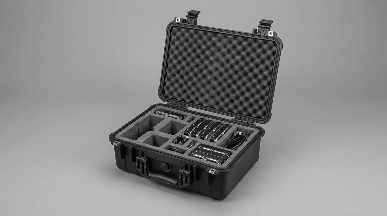
The liner's task is to locate the instrument and absorb shock, and location must come first. Every time an instrument shifts inside a case it transfers load into a connector or moves an optical element, so a compartment layout should have exactly one correct orientation for loading and unloading. The usual arrangement gives separate pockets to the instrument body, the probe, the cable and spares. The probe should be located independently rather than sharing a pocket with the body, so the two cannot strike each other. Cables belong in a dedicated channel coiled to a radius of at least ten times the cable diameter, avoiding the small-radius bends that eventually fatigue a shield or an insulation layer.
Cushioning materials are selected on hardness, resilience, energy absorption and mass. EPE is light, springy and inexpensive, which makes it the natural bulk energy absorber. EVA is denser and dimensionally stable, so it machines into accurate locating blocks. IXPE is thinner and tougher, suited to linings and surface protection layers. PE foam has a higher modulus and carries static loads well. For heavier instruments the sound combination is a rigid locating block plus a soft cushioning layer.
| Material | Density range | Rebound behaviour | Dimensional stability | Recommended role in the case |
|---|---|---|---|---|
| --- | --- | --- | --- | --- |
| EPE | roughly 20–35 kg/m³ | Good rebound, smooth energy absorption | Fair | Bulk cushioning, large pads |
| EVA | roughly 40–90 kg/m³ | Slower rebound, low deformation | Good | Precision-machined locating blocks |
| IXPE | roughly 30–60 kg/m³ | Stiff in thin sections | Good | Thin linings and surface layers |
| PE foam | roughly 25–60 kg/m³ | Rigid, good load bearing | Good | Structural supports and pads |
| Foamed silicone | Formulation-dependent | Stable over a wide temperature range | Good | Wide-temperature sealing and cushioning |
How the liner meets the shell must agree with the contamination-control objective. A removable liner should include a grab handle usable with gloves, and its outer profile should fit the cavity closely enough that particles cannot slip behind it. A fixed liner demands a cleaning route for the day contamination occurs, so that no inaccessible sandwich layer is created.
10. Clean-Zone and Dirty-Zone Logistics with Status Marking
The governing principle is one-way flow: dirty cases never enter clean areas, and instruments are never unpacked in contaminated areas. A common arrangement is dual-case transfer, in which the outer transport case stays outside and a clean inner case carries the instrument across the boundary, with both cases stored and decontaminated in their own zones. Even if the outer shell is contaminated, the transfer never exposes the instrument to an opening action. Across boundary movements the exterior must stay wipeable; soft wrapping and stretch film cannot be fully decontaminated and generate waste.
Status marking is how management requirements reach the physical case. Three markings are usually enough: a unique case number for asset and history tracking, the date and operator of the most recent decontamination so staff can judge whether another pass is due, and a recording position for the surface contamination reading taken before the case leaves the controlled area. The marking must survive washing, and updating the information must not damage the surface.
| Zone | Actions permitted | Required case condition | Record kept |
|---|---|---|---|
| --- | --- | --- | --- |
| Contaminated area | Load instrument, close case, wipe exterior | Seal intact, lifting points serviceable | Loading list and survey readings |
| Buffer room | Re-wipe exterior, change liner, open case | Exterior survey must pass before entry | Decontamination result, opening time |
| Clean area | Unload instrument, inspect liner | Cavity visibly free of particulate | Cavity inspection conclusion |
| Transport leg | Lift, stack, restrain | Latches closed, markings legible | Lifting method and stacking tiers |
11. Transport Profiles: ISTA, GB/T 4857 and Stacking Load
Transport verification should never be reduced to a single drop test. A complete profile covers vibration, shock, stacking and drop, with the ISTA series addressing packed-product performance and the GB/T 4857 series supplying the underlying test methods, while export programmes often reference an ASTM D4169 distribution cycle. Sequence and acceptance criteria are set out in this description of ISTA transport testing procedures. Two points deserve extra attention here. First, vibration accumulates over long journeys and may not cause immediate failure, yet it can slowly walk a locating block out of position. Second, stacking load matters because cases in storage are rarely placed the way the designer intended.
Stacking capacity should be assessed as maximum tier count multiplied by single-case mass, then multiplied by a safety factor of at least three, with warehouse temperature taken into account because plastics creep faster when warm. A summer store should therefore be stacked more conservatively than a winter one. Drop height is normally banded by case mass: the heavier the case, the lower the required drop height, a relationship set out in standard drop test methods. The specification should state the drop height for the applicable mass band rather than a vague requirement to pass a drop test.
| Test | Reference basis | Key parameters | Acceptance criterion |
|---|---|---|---|
| --- | --- | --- | --- |
| Random vibration | ISTA series, GB/T 4857 | Frequency range and spectrum set by route | No cracking, no liner displacement |
| Shock | GB/T 4857, ASTM D4169 | Half-sine peak acceleration and duration | Latches closed, instrument does not shift |
| Stacking | Stacking load test method | Load, duration, ambient temperature | Deformation within allowance |
| Drop | Drop test method | Height by mass band, edges, corners, faces | Sealing face intact, no through cracks |
| Low pressure | Air transport test methods | Simulated cabin pressure with differential monitoring | Seals neither collapse nor blow out |
12. Quality Control, Documentation and Acceptance Hold Points
Acceptance in a controlled area should deliberately separate front-end checks that have nothing to do with nuclear safety. The hold points at delivery include dimensional agreement with drawings, sealing-face roughness and score inspection, visual and penetrant examination of welds, liner fit and withdrawal force, latch and hinge cycle counts, and marking legibility. None involves a nuclear safety assessment; they are ordinary mechanical confirmations, and a checklist removes most disputes on site.
The document package should include material certificates with batch traceability, batch numbers of gaskets and relief valves, factory airtightness records with curves, measured liner fit dimensions, a packing list and an operating instruction. Users managing long service histories may also want a reserved marking position and a record slot on the case so that every decontamination, opening and repair leaves a trace. JUNZHIJIA supports custom liners and compartment layouts, dedicated tooling and OEM or ODM programmes, with cases manufactured by the company named in the Chinese specification, and documentation issued against the customer's template covering dimensional reports, airtightness records and packing lists.
| Hold point | Inspection method | Sampling guidance | Handling of nonconformance |
|---|---|---|---|
| --- | --- | --- | --- |
| External and fit dimensions | Tape, callipers, dedicated gauges | Full first article, AQL sampling thereafter | Quarantine the batch for review |
| Sealing face quality | Visual plus roughness gauge | 100 percent | Polish or scrap beyond the limit |
| Weld integrity | Visual plus penetrant testing | Sample structural welds | Re-weld and re-inspect |
| Liner fit | Feeler gauge plus withdrawal force | Full first article | Refit or remake the liner |
| Latches and hinges | Cycle operation test | Sampling | Replace the hardware |
| Factory airtightness | Pressure decay | 100 percent, curves retained | Retest; repair on failure |
Defining minor, major and critical defects in advance is far more reliable than judgement calls on the day of delivery.
Frequently Asked Questions FAQ
Q: Can a protective case shield gamma rays or neutrons?
A: No, and it should not be advertised that way. Effective gamma shielding requires high-atomic-number material in substantial thickness and mass, while neutron shielding needs hydrogenous or boron-loaded material, and neither is achievable in a portable case. Wrapping an instrument in steel or plastic attenuates radiation by an amount that is negligible in engineering terms. What the case can genuinely do is separate the instrument from the working environment: prevent mechanical damage, keep radioactive dust out of the cavity, remain cleanable, and let an operator open, close and lift the case with tools so that time spent close to it is shortened. That is a mechanical and environmental brief, not a radiological one. Dose control comes from time, distance, source management and personal protection, never from the box. If a purchase document contains the phrase radiation-shielding case, it should be deleted and replaced with verifiable sealing, cushioning and decontamination criteria. The correction protects both parties and removes a claim that cannot be substantiated.
Q: If a case is rated IP67, will a hose-down in the decontamination bay let water in?
A: It depends on whether the washing conditions exceed what that rating defines. The second digit of IP67 refers to short-term immersion under a specified depth and time. High-pressure washing is more severe in both pressure and dynamic impact, and normally falls under IP66 or IP69K instead. The practical route is to define what the site actually does. If washing means wiping and low-pressure rinsing, IP65 is usually sufficient. If a low-pressure hose is used, choose IP66. Only where brief immersion is realistic is IP67 needed. A case fitted with a pressure equalisation valve is additionally limited by the membrane inside that valve, so the valve must be specified and verified as a separate component rather than assumed to inherit the enclosure rating. Buying a higher rating than the site needs raises cost and opening force without adding real protection. Rating selection should follow the washing method the site will really use, not the harshest method it can imagine. That choice belongs in the purchase tender.
Q: Why is radioactive dust harder to deal with than water ingress?
A: Water entering a cavity usually announces itself as pooling or condensation, and the case can generally be dried and returned to service. Radioactive particulate behaves differently. It arrives in trace amounts and deposits on connectors, keypad gaps, optical window edges and liner sandwich layers, where it is invisible to the eye yet steadily raises background counts and contaminates anyone who touches the surface. Worse, once particulate becomes fixed contamination, wiping cannot remove it, and the remedy is usually to replace the liner or scrap the case outright. Design priority should therefore favour dust protection over water protection. The sealing face, the valve membrane and the liner fit should be judged against the scale of particles rather than the scale of droplets. Acceptance should also rely on wipe sampling with a surface contamination survey rather than a visual check of the cavity. That is why the liner, rather than the case wall, is often the part designed to be discarded, and it should be budgeted that way.
Q: How should I choose between a stainless steel case and a polypropylene case?
A: Start from decontamination frequency and intensity, not from unit price. If the case will undergo frequent chemical decontamination with traceable results, stainless steel is the better answer, because its surface tolerates solvents and mechanical wiping, and after treatment its welds present almost no adsorptive porosity. The drawbacks are mass, rapid heat conduction and condensation on the inner wall during cold transfers, which needs deliberate mitigation. If the case is mainly lifted and transferred, if decontamination means wiping with a neutral detergent, and if impact resistance and low mass matter more, rotomoulded polyethylene is the better fit, at the cost of surface scratching and slightly stronger adsorption. Where the instrument is valuable and budget allows, a hybrid of structural frame plus stainless inner liner is the strongest option: the liner provides the contamination-controlled face and the shell carries mechanical load, and a contaminated liner can be exchanged on its own. Cost comparisons should therefore cover the whole service life rather than the invoice alone.
Q: How often should the gasket be replaced?
A: A fixed calendar interval is of limited use; replacement should follow a condition criterion. There are two readily measured triggers. The first is compression set exceeding 30 percent of the initial compression. The second is recovery to less than 85 percent of nominal section height when the seal is free. In service, the trend in factory airtightness records is the most practical indicator: if pressure decay values for a given model rise steadily across successive tests, the sealing face or the gasket is deteriorating. Replacement must begin with cleaning the groove and inspecting the metal sealing face for grit scores. Where a score exceeds the permitted depth it must be dressed before a new seal is fitted, otherwise the new gasket leaks along the same line. Confirm that no cleaning agent residue remains in the groove, and allow the new seal to settle before closing the case. A written replacement record for each case turns this from guesswork into routine maintenance.
Q: Does the inside of the case need desiccant?
A: That depends on the humidity profile of the transport route. For shipments from a dry region into a humid one, or on routes where day and night temperatures cause condensation on the inner wall, a desiccant charge with a humidity indicator card is worthwhile. The card window should be readable without opening the case, and the reading should be taken before the case is opened so that the decision to dry the contents is informed rather than assumed. Desiccant cannot compensate for poor sealing or a badly fitted liner: if the sealing face leaks, the desiccant saturates quickly and merely disguises the real fault. Structurally, closed dead spaces should be avoided and air should be able to circulate from the cavity to the desiccant, otherwise local pockets can still condense moisture even when the average cavity humidity looks acceptable. Desiccant is a consumable, so the quantity should be calculated from cavity volume, route duration and sealing class, then written into the packing procedure.
Q: What geometry does remote handling actually demand?
A: At least four requirements. First, the relationship between lifting points and centre of gravity: paired lifting points should sit as close as possible to the loaded centre of gravity, ideally within 30 mm horizontally, because a large offset makes the case tilt in the air and loads the liner and instrument sideways. Second, handle opening dimensions must accept a gloved hand or a manipulator jaw, generally at least 40 mm of clear height, with a retaining lip to stop slipping. Third, external protrusions must be controlled: zip pulls, clip loops and standing screw heads snag gloves, hoses and airlock fabric, so they should be flush or recessed. Fourth, closure operations should be simplified, with a single-action latch preferred over a mechanism needing both hands at once, so an operator can complete the task and step away quickly. These four points cost little at the design stage and save real time in service, so they should be confirmed on a mock-up before tooling is cut.
Q: What information is needed to order a custom liner and compartment layout?
A: A three-dimensional model of the instrument, or at minimum accurate overall dimensions and the position of its centre of gravity, is the starting point. The team also needs to know which areas are most fragile, such as optical windows, probe connectors, displays and electrical interfaces, because those define where the liner must not apply pressure. Second come transport conditions: maximum drop height, stacking tiers and transport mode, which together set cushion thickness and locating-block stiffness. Third are operating requirements: how the instrument is removed, whether gloves are worn, whether tools are used, and whether the action must be possible one-handed. Fourth are decontamination requirements, which decide whether the liner must lift out as one piece and whether it may be washed or only wiped. With this information a first-article case is normally built to confirm the loading posture before batch production.
Conclusion and Related Reading
Nuclear instrument cases are not improved by extra thickness. They improve when two constraints become material, geometry and test clauses: never imply shielding, and never become a new contamination source. JUNZHIJIA designs from the instrument's real route between zones.
Related Reading