

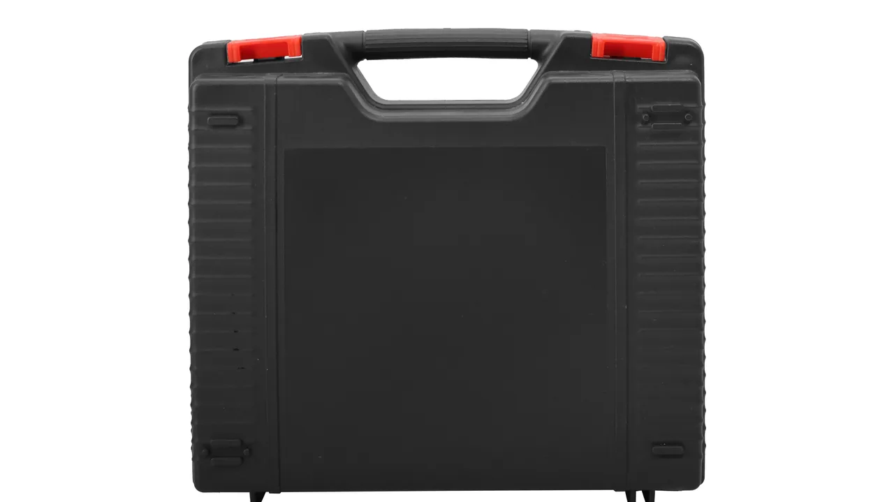
The critical parts of a pipe extrusion line share one profile: long, slender, precision-finished, and effectively impossible to repair on site. An extrusion screw is often 1.5–3 m long with a nitrided case only 0.3–0.5 mm deep; knock a chip off a flight crest and the feed-zone conveying efficiency and melt-temperature uniformity change permanently. A sizing sleeve is bored to H7 or tighter; press an oval into that bore or drag an axial score along it and the pipe outside diameter and roundness go out of tolerance. A breaker plate is polished, sometimes chrome-plated; any indentation creates a stagnation cell in the melt path that later produces degraded resin and periodic black specks. What road transport delivers to these parts is precisely the impact and local pressure that cause irreversible damage.
JUNZHIJIA builds its protection principle for pipe extrusion components on three commitments: continuous cradle support along the full length of the screw to eliminate unsupported bow, end-face guards and soft overlays to protect the mating faces of sizing sleeves and breaker plates, and separated compartments to block galvanic corrosion between nitrided and stainless parts. A case is not judged by how many parts it holds, but by whether the longest free span inside it is held below the safe value and whether every mating face rests on its own soft support. This article works through screws, sizing sleeves, breaker plates and accessories, and gives support spacings, corrosion parameters and acceptance values that can go straight into a technical agreement.
Table of Contents
- Nitrided Screw Surfaces: Brittle Failure at Flight Crests and Thread Flanks
- Screw Length-to-Diameter Ratio and Internal Support Spacing
- Sizing Sleeve Bore Tolerance and Cylindricity Preservation
- Vacuum Grooves and Chamfered End Faces: Preventing Local Collapse
- Breaker Plate Flow-Channel Faces: Scuffing and Indentation Control
- Keeping Core and Die Matched Sets Together
- Long-Part Cradles: V-Grooves, Soft Overlays and Strap Tension
- Separating Nitrided Parts from Stainless Steel to Block Galvanic Corrosion
- Compartment Storage for Heater Bands and Thermocouples
- Residual Resin Removal and Anti-Stick Isolation on Screws
- Horizontal, Vertical or Lifted: Case Orientation and Lifting-Point Design
- Unpacking Verification and Screw Runout Re-Measurement
- Frequently Asked Questions FAQ
- Conclusion and Related Reading
Nitrided Screw Surfaces: Brittle Failure at Flight Crests and Thread Flanks
Screw surface hardening is normally done by gas or plasma nitriding, producing a hardened case 0.3–0.5 mm deep with a surface hardness of HV 900–1100. The premium on hardness is paid in toughness: the nitrided layer behaves as a thin brittle shell. Under point impact it does not yield like quenched and tempered steel; it spalls in shell-shaped flakes and starts micro-cracks. Once that shell is broken, the soft substrate beneath wears rapidly in compounds containing glass fibre, calcium carbonate or metal powder, and a local crater forms that changes conveying behaviour along the whole screw.
Three locations carry the highest risk in transit. The flight crest is first, because the crest-to-barrel clearance is the tightest dimension on the screw; a chip there opens the clearance. The screw-head face that mates with the non-return ring is second, because the fit is precise and the sealing function depends on it. The spline or keyway at the drive end is third, because it transmits torque and any dent makes assembly difficult. Treat all three separately in the packing design: cradle the crest in symmetrical half-round soft supports so it sees distributed pressure rather than shear; fit a soft end cap with a flock inner face over the head; slide a non-woven sleeve over the spline before it goes into its locating block.
Two rules belong in the work instruction as well. First, never handle a nitrided screw with bare hands — chloride in perspiration degrades the passive state of the nitrided surface, which shows up as pitting weeks later in storage rather than immediately. Second, never sling a screw with wire rope, because the strand crowns abrade a bright band into the nitrided layer under vibration; use nylon slings with soft sleeves and pad the lift points.
| Screw location | Failure mode | Consequence | Packing measure |
|---|---|---|---|
| --- | --- | --- | --- |
| Flight crest | Nitrided-layer spalling | Lower conveying efficiency, opened clearance | Half-round soft supports, even pressure |
| Head mating face | Indentation and galling | Non-return ring no longer seals | End cap with flock liner |
| Drive spline | Crushed key teeth | Hard assembly, irregular torque transfer | Sleeve plus locating block |
| Full length | Unsupported bow | Straightness out of tolerance | Multi-point support, limited free span |
| Bore and flights | Coked resin | Black specks at start-up, long purge | Resin removal plus anti-stick isolation |
Screw Length-to-Diameter Ratio and Internal Support Spacing
The classic failure inside a case is a slender bar carried at two ends with nothing in the middle. Take a nitrided screw of 90 mm diameter, 2400 mm long and 95 kg. Supported only at its ends, with a 2000 mm free span, the deflection produced by self-weight and transport vibration clearly exceeds the allowance. Worse, most of that deflection is elastic: nothing looks wrong at unpacking, yet on the machine the screw rubs the barrel on one side, and melting becomes uneven.
The parameter to control is therefore the maximum free span, not the number of supports. Shop practice is to hold the maximum free span within 15–20 times the screw diameter and to verify with a three-point check. For the 90 mm screw above, the free span should stay between about 1350 mm and 1800 mm, so a 2400 mm screw needs at least three support groups — both ends and the middle. Longer screws need an extra group every 800–1000 mm, and the height difference between support points must stay within 0.5 mm, otherwise the packing itself introduces a pre-bend.
Prefer V-blocks or half-round cradles over flat pads. Contact length should be 0.5–0.8 times the screw diameter, faced with 20–25 Shore 00 EVA or IXPE. A flat pad contacts a cylinder along a line, which produces high local stress and indents the crest. Once supported, fit a removable top bar or elastic strap over the screw; a strap that sinks 3–5 mm under finger pressure is about right, while an over-tensioned strap adds a pre-bending load of its own.
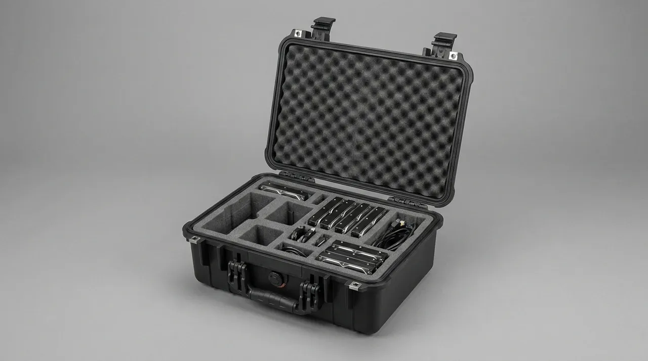
Sizing Sleeve Bore Tolerance and Cylindricity Preservation
Sizing sleeves — vacuum types and water-ring types alike — are bored to H7 or even H6 with an internal roughness of Ra 0.2–0.4 μm, and the wall is thin. A 250 mm outside diameter sleeve may have a wall of only 12–18 mm. Carried at two points, such a thin-walled cylinder sags into an oval under its own weight; squeezed laterally, it dents locally. Once cylindricity is lost, pipe outside diameter fluctuates periodically and circumferential cooling is no longer uniform.
Handle sizing sleeves in one of two ways: stand them vertically, or lay them down with full circumferential support. Standing, the base needs a complete soft ring, nothing may be stacked on top, and at least 20 mm of headroom should remain in the case. Laying down requires a half-round cradle matched to the bore with a contact arc of at least 120°, repeated every 300–400 mm along the axis. The practice to rule out entirely is a single wooden batten pushed through the bore as support: under vibration it scores the bore axially, and an axial score is a direct source of surface defects on the pipe.
Internal cleanliness matters just as much. After removal from the line, a sizing sleeve usually carries scale and dust drawn in by the vacuum system, and that residue behaves like an abrasive during transport, fretting back and forth across the bore. Wash with warm water and a neutral cleaner, rinse with deionised water, dry with compressed air, then apply a very thin volatile corrosion inhibitor. If the sleeve will not return to a line for a while, insert a PE film liner, wrap the outside in non-woven, and plug both ends with soft caps.
Vacuum Grooves and Chamfered End Faces: Preventing Local Collapse
Vacuum sizing sleeves carry annular vacuum grooves and closely spaced extraction holes on the outer or inner wall. Grooves are typically 2–4 mm wide and 3–6 mm deep, and the groove edge is a stress raiser. Two damage modes dominate: rolled groove edges and crushed extraction holes. When the sleeve is loaded by other parts, or a support point lands exactly on a groove band, the edge deforms locally, vacuum distribution becomes uneven and pipe wall thickness drifts in a repeating pattern.
Move the supports clear of the groove bands. Leave a 50–80 mm support band at each end of the sleeve and load only there. If the grooves run the full length, spread the load over the whole circumference with a continuous soft ring and never use a local pad. The chamfered entry angle is a second weak point: the sharp edge chips readily under lateral impact, so fit a soft end ring matched to the bore, with an outside diameter slightly smaller than the sleeve so the ring itself never becomes a load path.
Protect the extraction holes the way you would protect small parts: plug or tape them with matched soft bungs to keep dust out of the vacuum chamber. The closure must peel off cleanly without adhesive residue, and the removal step must appear on the packing list so nobody powers up with a sleeve still sealed. Where the sleeve has a water jacket, the protruding inlet and outlet fittings need foam collars and a clearance pocket in the case wall. Comparable end-face plugging and full-ring support practice for tube-bodied parts is set out in Heat Pipe Equipment Cases: Transport Protection for Tube Bodies and End Caps.
Breaker Plate Flow-Channel Faces: Scuffing and Indentation Control
Breaker plates and filter plates are polished, sometimes chrome-plated, with flared lead-ins at every hole. Once the flow face carries an indentation, melt forms a stagnation eddy there, degrades over a long run, and then travels downstream as periodic black specks on the pipe bore. The defect usually surfaces only after product contamination, and tracing it means stripping the die head section by section — an expense far beyond the packaging budget.
The protection rule has three parts: faces never touch, edges never carry load, holes never collect dust. Faces never touch means two breaker plates must never be stacked face to face; interleave each with non-woven or PE foam sheet and keep at least 5 mm of margin all round. Edges never carry load means a plate must never stand on its rim with the flow face in bending; lay it flat on a full-surfaced soft pad, or stand it between two full-face clamping boards. Holes never collect dust means every flow channel is blown clean with filtered compressed air and taped before packing.
A breaker plate weighs 20–80 kg and invites single-handed lifting by one edge, which rolls the rim. Fit removable handles, use a dedicated carrying board, or cut two hand recesses into the liner so the operator must support the underside with both hands. The same discipline — large contact area, soft contact material, never loading a mating face — governs precision taper fits and is described in Machine Tool Holder Cases: Transport Protection for Taper Faces and Pull Studs.
| Breaker plate risk | Cause | Effect | Measure |
|---|---|---|---|
| --- | --- | --- | --- |
| Flow-face indentation | Contact with hard objects or stacking | Coked resin, periodic black specks | Flat single-layer packing plus interleaf |
| Flared hole distortion | Squeezed hole edges | Altered melt velocity profile | Hole taping plus flat support |
| Rim rolling | One-edge lifting | Poor seating after assembly | Two-hand support or carrying board |
| Seal-face corrosion | Humidity plus perspiration | Joint leakage | VCI film plus coated gloves |
| Chrome-layer lifting | Cleaning residue | Rough surface, resin adhesion | Neutral cleaning plus full drying |
Keeping Core and Die Matched Sets Together
The core and die of a pipe head set the inner and outer diameter and the wall-thickness distribution, and they normally leave the factory with a matched pair marking or a lapped fit. Packing them in separate cases is a common mistake: the assembly then has to be re-aligned on site, and if the marking has been rubbed off in handling, matching must be redone by measurement — slow and open to error. The correct approach keeps core, die, adjusting ring and locking ring as one set, fixed in the same case in the relative positions they occupy when assembled.
Two methods work. The first is shipping in the assembled state: build the head up in the factory exactly as it runs, drop the assembly into a shaped liner cut to its outline with a soft contact layer, and add elastic hold-down blocks in the lid to stop axial movement. The second is shipping in separated but indexed positions: cut an individual pocket for each part, lay the pockets out in the same left-to-right order as the assembly drawing, and print the pair number and orientation mark beside each pocket. The assembled method suits small and medium head sizes; the indexed method suits large heads and shipments where parts must be weighed separately for customs.
Either way, adjustment bolts and locking nuts must not float loose. These fasteners are often non-standard and cannot be replaced locally, and a lost bolt delays start-up directly. Provide a divided fastener tray inside the case, segregated by size, with the standard tightening torque printed on the tray label.
Long-Part Cradles: V-Grooves, Soft Overlays and Strap Tension
The long-part cradle is the structural heart of pipe extrusion packaging: its stiffness fixes the attitude of screws, sizing sleeves and long cores throughout the journey. Cut cradles from high-density EVA at 60–90 kg/m³; where spans are long, embed an aluminium or plywood skeleton to raise stiffness. Low-density EPE belongs in the void-filling role only, never as a load-bearing structure.
Open the V-groove to 90–120°. A narrower angle gives too small a contact band and high local stress; a wider angle weakens lateral location and the part can roll. Face both flanks and the bottom of the groove with 2–3 mm IXPE, and keep butt joints out of the load zone, because a joint edge becomes an indentation line under vibration. Set the cradle height so the centre of gravity of the long part sits in the lower third of the case, which lowers the overall centre of gravity.
Strap choice and tension are equally decisive. Nylon webbing is safer than wire rope and more stable than rubber; use 25–50 mm widths, metal buckles, and soft covers over the buckles. Judge tension by pressing the webbing, which should sink 3–5 mm. Place straps over support points rather than mid-span, or they will bend the part locally. Any part longer than 2 m needs at least two straps, symmetrically placed. Where one case must hold bars of very different lengths, use a Removable Divider Systems for Protective Cases: Compartment Layout and Installation approach to segment the interior by length so shorter parts cannot slide freely beside longer ones.
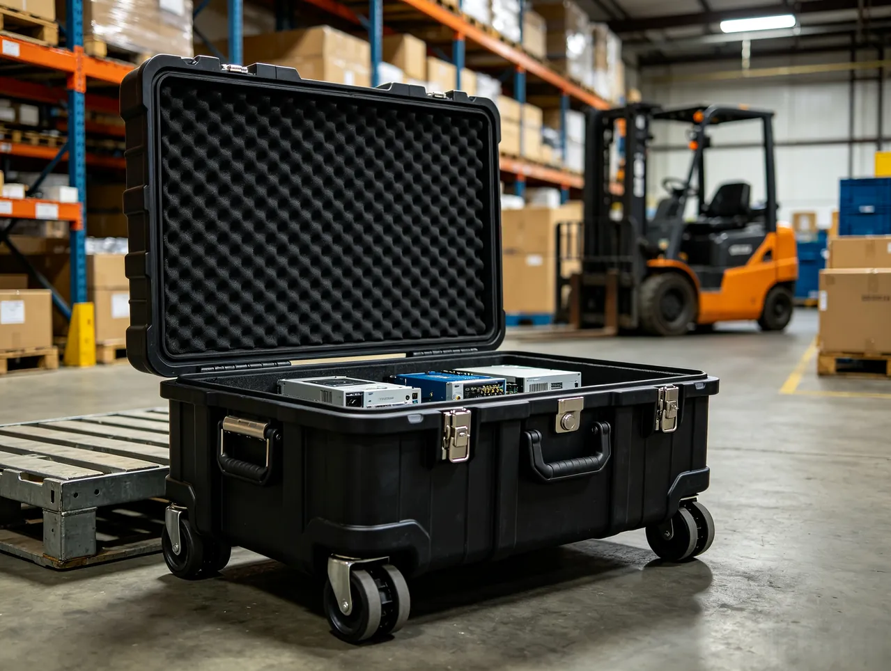
Separating Nitrided Parts from Stainless Steel to Block Galvanic Corrosion
Nitrided screws and nitrided cores are surface-modified steel, while breaker plates, sizing sleeves and fittings are often stainless or chrome-plated. Put the two families in direct contact in a humid environment and a galvanic couple forms. Once the nitrided layer develops a micro-crack or a spall, the exposed substrate sits at a different potential from the stainless part and corrodes several times faster than it would alone. Add condensation inside a trailer and perspiration from handling, and visible rust appears within months.
Three routes block the couple, and they work best in combination. Physical isolation separates the dissimilar metals completely with non-woven, PE film or IXPE sheet. Environmental control holds relative humidity inside the case below 40 %RH with desiccant and a humidity indicator card on the inside of the lid. Chemical protection applies a volatile corrosion inhibitor that adsorbs as a molecular film on the metal surface. Used alone, each route delays rather than stops the process.
Calculate the desiccant charge from the free internal volume rather than the external footprint; a common starting point is two to three grams of silica gel per litre of free space, with molecular sieve dosed at a slightly lower mass per litre. If the case has a gasket and is intended for repeat use, replace the desiccant after every opening and record the replacement date. Surfaces must be fully degreased and free of perspiration before treatment, so place a wash point and a supply of powder-free nitrile gloves beside the packing station; otherwise oil from the previous operation simply travels into the packing step.
Compartment Storage for Heater Bands and Thermocouples
Among pipe extrusion accessories, heater bands and thermocouples are the most consistently underestimated. Ceramic and mica heater bands contain brittle internal insulation; a drop or a local squeeze can crack them internally while the shell still looks perfect, and the band then heats unevenly on power-up. A thermocouple with a sheathed probe does not break when bent, but its measuring junction shifts, and the whole temperature curve drifts with it.
Two rules govern band storage: the bore must never carry load, and the lead must never be pulled. Support each band on a cylindrical mandrel matched to its bore diameter so it sits on the mandrel rather than being laid flat and flattened, and coil the lead separately, secured with hook-and-loop tape at a bend radius of at least ten times the cable diameter. Label each band with size, wattage and voltage to prevent mix-ups on site. Ceramic and mica bands belong on the upper layer of the case, separated from heavy metal parts by a rigid divider so a dropped part cannot strike them.
Store thermocouples and compensating cable in their own compartment. Cap the connectors, seal the terminals in a moisture-barrier bag, and where several calibration types share one case, label each compartment with the type letter and cable length. Mixing types at the terminal block silences or skews the whole line's temperature control, and that kind of fault typically costs hours to find.
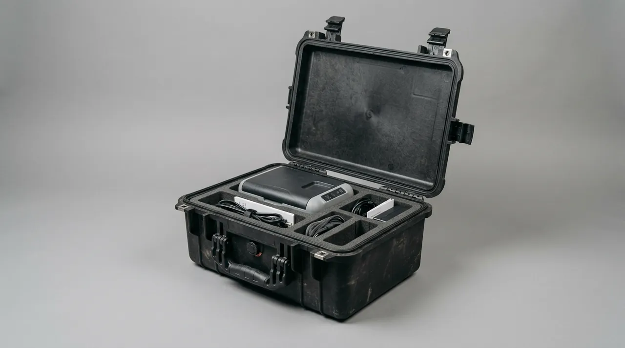
Residual Resin Removal and Anti-Stick Isolation on Screws
A screw pulled straight off a running line usually carries a layer of resin, thickest at the flight roots and around the non-return ring. In transit that residue absorbs moisture, and some polymers — PVC, PA and PC in particular — slowly decompose under warm humid conditions and release acidic species that attack the steel directly. The residue also glues dust into the flights, creating an abrasive layer that frets the screw surface for the whole journey.
Clean in three steps. First, while the screw is still hot, remove bulk resin with a copper scraper or a dedicated purging compound; steel scrapers, abrasive paper and wire brushes are prohibited because they scratch the nitrided layer. Second, if the screw has already cooled, either purge it at low speed with a suitable purging compound or pyrolyse it in a cleaning oven at 400–450 °C, then blow out the ash completely. Third, immediately after cleaning, spray a thin anti-rust grease or volatile corrosion inhibitor and cover with PE film.
For the flights themselves, wrap in non-woven and overwrap with PE film, winding along the flight direction so that no non-woven edge becomes trapped between flight root and crest. Screws with an internal bore for cooling water or a core rod need the same drain-and-dry treatment as any water circuit: purge, dry, plug both ends, and label each plug "drained" with the date.
Horizontal, Vertical or Lifted: Case Orientation and Lifting-Point Design
Case orientation decides the load path. Screws and long cores travel horizontally, because horizontal packing makes it easy to add support points, keeps the centre of gravity low and resists tipping. Sizing sleeves and short cores travel vertically, because a vertical stance allows full-ring support and avoids ovalisation. Breaker plates always travel flat, never stacked directly on one another. Where one shipping unit contains all three families, put heavy and long parts on the lower layer and precision accessories on the upper layer, separated by a rigid divider.
Align lifting points with the centre of gravity. Place them at the quarter and three-quarter points along the case length, using removable lifting eyes or recessed lifting slots, and print three markings on the outside: centre of gravity, no single-side lifting, and do not invert. For cases longer than 2.5 m, fit bottom skids with forklift entry markings, and match the skid spacing to the fork spacing so a forklift cannot be driven in from the side and dent the wall.
For stacking, ship long-part cases in a single layer or at most two, with the upper case no more than 60 % of the lower case's rated capacity. Where multiple layers are unavoidable, run corner posts so the load travels down through the posts rather than through the lid and walls. This matters most in warehousing, where long-term static load produces creep that cannot be reversed. Stacking layer calculations and pallet layouts are covered in Protective Case Stacking and Pallet Planning: Load Calculations and Container Layout. On the vehicle, long cases should run along the trailer axis with fore-and-aft restraints; a crosswise case surges forward under emergency braking.
Unpacking Verification and Screw Runout Re-Measurement
Unpacking verification is the final verdict on transport quality. Work in this order: inspect the case exterior for dents, punctures and moisture traces, and download the logger data and read the humidity indicator card; open the lid and check the packing list against part numbers, looking for shifted parts, slack straps and deformed pockets; then re-measure three geometric indicators — screw straightness or runout, sizing sleeve bore cylindricity, and breaker plate flow-face flatness.
For the screw, use V-blocks and a dial indicator to read radial runout at three points — both ends and the middle — and compare with the dispatch record; a deviation above 0.05 mm needs investigation. For the sleeve bore, use an internal micrometer or CMM to sample four cross-sections in two directions each, and treat an ovality above 50 % of the tolerance as an anomaly. For the breaker plate, check the flow face with a straight edge and feeler gauge; a 0.05 mm feeler must not enter. Record every reading in an arrival inspection record and file it with the dispatch data.
If something is wrong, photograph it at the unpacking site and notify the carrier and supplier while the goods are still in place and the packaging intact. Many claims fail simply because the parts were moved into the workshop and the packaging discarded before the objection was raised, destroying the evidence chain for transport liability.
Frequently Asked Questions FAQ
Q: A small piece of the nitrided layer has chipped off the screw. Can it still be used?
A: That depends on where the spall sits. If it is on a flight crest in the feed zone and covers only a small area, first measure the clearance to the barrel at that point. Where the increase is no more than 20 % of the design value, the screw can run short term, but the measurement must be logged and a replacement scheduled. If the spall is on a crest in the metering or compression zone, it changes melt conveying and pressure build-up directly, and the screw should be taken out of service. What matters even more is stopping the damage from spreading: the exposed soft substrate wears rapidly in compounds containing glass fibre or calcium carbonate and opens into a crater that traps resin and generates black specks. A high-temperature repair compound can be used as a stopgap and sanded flush with the crest, but its life is limited. The lasting fix belongs in the packing design, where crests rest on half-round soft cradles instead of wire slings.
Q: How many support points does a screw need inside a case, and is there a rule of thumb?
A: The governing parameter is the maximum free span, and shop practice holds it within 15–20 times the screw diameter. For a 90 mm screw, that means a free span of roughly 1350–1800 mm, so a 2400 mm screw needs at least three support groups; beyond 3000 mm, add one group every 800–1000 mm. The height difference between neighbouring supports must stay within 0.5 mm, because a larger step applies a pre-bending load that the screw will carry for the whole journey. Choose V-blocks or half-round cradles with a contact arc of 0.5–0.8 times the diameter and a facing of 20–25 Shore 00 EVA or IXPE; flat pads contact along a line and indent the crest. Place straps over support points rather than mid-span, and use at least two symmetrically for anything over 2 m. For screws carrying a worn crest or an existing repair, add one extra support group and reduce the free span by roughly 20 %, because a locally thinner section bends more readily than the original profile.
Q: The sizing sleeve bore is held to a very tight tolerance. How do we stop it deforming in transit?
A: Remove both local squeeze and self-weight bending. Standing vertically, the sleeve needs a complete soft support ring underneath, nothing stacked on top, and at least 20 mm of headroom. Laid horizontally, it needs a half-round cradle matched to the bore with a contact arc of at least 120°, repeated every 300–400 mm along the axis. The practice to avoid completely is a single wooden batten through the bore as a support: under vibration it scores the bore axially, and an axial score transfers directly to the pipe surface. Vacuum groove bands should not serve as support points; keep a 50–80 mm support band at each end, and where the grooves run full length, spread load over the whole circumference. On arrival, measure four cross-sections in two directions each with an internal micrometer and treat ovality above 50 % of the bore tolerance as an anomaly. Measure with the sleeve resting on its shipping cradle, since the support condition itself changes the reading, and record ambient temperature alongside the figures so warm and cold measurements are never compared directly.
Q: What does an indentation on a breaker plate flow face actually cause, and how is it prevented?
A: The indentation creates a stagnation eddy in the melt path, material dwells there long enough to degrade, and the degraded resin travels downstream as periodic black specks on the pipe bore. Tracing the source normally means stripping the die head section by section, at a cost far above the price of proper packaging. Prevention follows three rules: faces never touch, edges never carry load, and holes never collect dust. Never stack two plates face to face; interleave with non-woven or PE foam and keep 5 mm margins. Always lay a plate flat on a full-surfaced soft pad, or stand it between two full-face clamping boards rather than on its rim. Blow every flow channel clean with filtered compressed air and tape it before packing. Carry plates with both hands supporting the underside, or with a dedicated carrying board, never by grabbing one edge. Where a plate must stand vertically, use two full-face clamping boards and tighten them evenly, because a single clamp at the centre loads the plate like a simply supported beam.
Q: Nitrided screws and stainless breaker plates in one case — will they really corrode each other?
A: They can, but three conditions must coincide: direct contact between dissimilar metals, an electrolyte such as condensation or perspiration, and a micro-crack or spall in the nitrided layer. Once the layer is broken, the exposed substrate forms a galvanic couple with the stainless part and corrodes several times faster than it would alone, with visible rust appearing within months. Block it with three measures used together. Separate the two material families physically with non-woven or IXPE sheet. Control the environment by holding relative humidity below 40 %RH with silica gel or molecular sieve and monitoring it with an indicator card on the lid. Apply a volatile corrosion inhibitor to form an adsorbed molecular film. Degrease and de-sweat every surface before treatment, and keep powder-free nitrile gloves at the packing station so oil from the previous operation is not carried in. Check the indicator card weekly during long storage, because a case opened even briefly resets the humidity inside and shortens the remaining life of the desiccant.
Q: The heater band looks perfect, so why does it heat unevenly after installation?
A: Ceramic and mica heater bands contain brittle internal insulation. A drop or a local squeeze can crack that insulation while the outer shell shows no mark at all, leaving the resistance wire partly shorted or poorly contacted; on power-up the band heats slowly, overheats locally, or oscillates in temperature. Two rules govern transport. The bore must never carry load, so support each band on a cylindrical mandrel matched to its bore instead of laying it flat and flattening it. The lead must never be pulled, so coil it separately, secure it with hook-and-loop tape, and keep the bend radius at least ten times the cable diameter. Label each band with size, wattage and voltage to prevent mix-ups. Store ceramic and mica bands on the upper layer with a rigid divider between them and any heavy metal part. Before installation, check each band's resistance and insulation with a megohmmeter, because that is the only reliable way to find insulation damage that leaves no external mark. Replace the desiccant whenever the indicator card shows a rise, since a soft band that has absorbed moisture is far more likely to fail on first heat.
Q: How thoroughly must residual resin be removed from a screw taken straight off the line?
A: Thoroughly enough that no residue is visible and nothing has accumulated at the flight roots. Residual resin absorbs moisture in transit, and polymers such as PVC, PA and PC decompose slowly under warm humid conditions and release acidic species that attack the substrate directly. The residue also glues dust into the flights, forming an abrasive layer that keeps fretting the screw for the whole journey. Clean in three steps: while hot, remove bulk resin with a copper scraper or purging compound, never with steel scrapers, abrasive paper or wire brushes, which scratch the nitrided layer; once cool, either purge with a suitable compound or pyrolyse at 400–450 °C and blow out all ash; then immediately apply a thin anti-rust grease or volatile corrosion inhibitor and cover with PE film. Screws with an internal bore also need drain-and-dry and dated plugs. Photograph the cleaned screw before it is wrapped, because a dated image settles most disputes about whether residue was left behind at dispatch. Log the cleaning date on the case label as well, so the interval between cleaning and first start-up can be checked later.
Q: Which geometric indicators should be re-measured on arrival, and what are the acceptance criteria?
A: Re-measure three. For the screw, read radial runout at three points with V-blocks and a dial indicator, and investigate if the reading deviates from the dispatch record by more than 0.05 mm. For the sizing sleeve bore, sample four cross-sections in two directions each with an internal micrometer or CMM, and treat ovality above half the bore tolerance as an anomaly. For the breaker plate, check the flow face with a straight edge and feeler gauge; a 0.05 mm feeler must not enter the gap. Alongside these, download the logger data, read the indicator card and check the packing list against part numbers. If anything is wrong, photograph it on site with the packaging intact and notify the carrier and supplier before the goods move.
Conclusion and Related Reading
Screw free span, sleeve ovality and breaker plate feeler readings decide whether a pipe line restarts on schedule. JUNZHIJIA builds high-density long-part cradles, full-ring soft supports, separated compartments and VCI protection, with OEM/ODM tooling.
Related Reading