

In the secondary systems of 110 kV and above substations, relay protection equipment is the most sensitive link in the entire safety chain. A single protection panel is densely packed with relay modules, terminal blocks, test links, optocoupler isolation boards and bundled secondary wiring, while current transformers and voltage transformers scale primary current and voltage down into signals the protection device can actually process. Between leaving the factory, entering a warehouse, being transferred between provinces and being swapped out during an overhaul, this equipment almost always passes through long road hauls, multi-stage transshipment, open-air short-term storage and on-site lifting. A significant share of field-reported maloperation, sampling drift and missing remote signals does not trace back to assembly error at all, but to one unremarkable jolt in transit, one rainy season of moisture ingress, or one fingertip-level electrostatic discharge.
The real value of protection equipment is not the steel thickness of the cabinet but the integrity of every signal behind it; JUNZHIJIA treats the protective case as a "movable panel environment" for secondary systems, where anti-vibration, moisture, ESD and accidental-contact defenses must all hold at once so the equipment is effectively already in its substation operating condition the moment the lid opens.
Table of Contents
- Why Relay Protection Equipment Needs a Dedicated Protective Case
- Six Typical Risks in Panel Storage and Transport
- Protection Requirements for Current and Voltage Transformers
- Securing Terminal Blocks, Test Links and Secondary Wiring
- Optocoupler Modules and ESD Protection
- Case Material and Structural Selection Compared
- Sealing Ratings: IP65 versus IP67 Criteria
- Cushioning Liners and Compartment Design
- Latches, Hinges and Pressure Equalization Valves
- Stacking Load and Transport Test Verification
- Temperature, Humidity, Condensation and Salt Spray Control
- Commissioning, Calibration and Unpacking Acceptance
- Customization, Tooling and OEM/ODM Services
- Frequently Asked Questions FAQ
- Conclusion and Related Reading
Why Relay Protection Equipment Needs a Dedicated Protective Case
The weak points of relay protection equipment do not align with the intuitive rule that only heavy things fear a drop. Its modules are plug-in assemblies packed with surface-mount components, electrolytic capacitors, relay coils and transformer windings, all of which are unusually sensitive to high-frequency vibration and resonance. Its terminal blocks rely on thin-plated copper alloy spring contacts, so once moisture tracking or oxidation begins, contact resistance drifts. Its optocouplers and communication interface chips have gate oxide breakdown voltages of only tens of volts, meaning ordinary human static can cause invisible damage.
What ties these failure modes together is that none of them announce themselves on arrival. They surface during the first fault recording event after commissioning. A dedicated protective case exists precisely to defeat that delayed emergence. It has to deliver four capabilities simultaneously: a rigid shell that isolates stacking and impact loads, an elastic liner that attenuates random vibration to a level the modules tolerate, a sealed construction that blocks moisture and dust, and a conductive or dissipative path that drains static charge to ground.
| Failure Mode | Root Cause | Case Countermeasure |
|---|---|---|
| --- | --- | --- |
| Solder joint cracking in modules | Road-transport random vibration and resonance | Low-density foam multi-point support tuned away from 20-80 Hz |
| Rising terminal contact resistance | Moisture ingress and condensation | IP65/IP67 sealing plus desiccant and humidity indicator |
| Optocoupler or comms chip breakdown | Human or plastic-friction static | ESD foam (surface resistivity 10^6-10^9 ohm) plus ground stud |
| Transformer core rust and moisture | Open-air storage in the rainy season | Vacuum foil bag, sealed shell, pressure equalization valve |
| Shell deformation and panel scuffing | Over-stacking and unpackaged handling | Reinforcement ribs, separate compartments, corner guards |
| Lost nameplates and wiring diagrams | Reopening and shuffling on site | Dedicated document pocket fixed inside the liner |
The table makes clear that a protective case is not a simple shipping container but an engineered answer to specific failure mechanisms. For the wider picture see Substation Equipment Protective Cases; this article focuses on the secondary side, namely relays, transformers and panel accessories.
Six Typical Risks in Panel Storage and Transport
A protection panel usually leaves the factory already partially commissioned, with modules, test links and wiring all in place. The six transport risks below are ordered from most to least frequent.
The first is vibration and shock. The panel frame itself is rigid enough, so the parts that actually take load are the cantilever-mounted modules and cables. On a national highway, a flatbed floor can sustain peak accelerations above 0.5 g for extended periods, and bridge expansion joints produce transient shocks of 1-2 g.
The second is tilting and inversion. A protection panel has a high center of gravity, and transporting it on its back lets module weight press down on the guide rails, which can deform them over a long journey. Upright orientation throughout is mandatory, and the case should enforce this structurally rather than merely printing an arrow.
The third is dust and metal swarf. Once cutting or grinding dust enters module gaps and then absorbs moisture, it forms conductive paths, a common trigger for protection maloperation.
The fourth is rain and condensation. In environments with a large day-night temperature swing, the inner wall of a sealed case condenses, and droplets run down onto the terminal blocks.
The fifth is crushing from stacking. Sites routinely stack cases two or three high to save floor space, and if the case does not declare its stacking tier, the lower lids are crushed.
The sixth is accidental human contact. After opening, a test link is nudged, or a wire is snagged, and this invisible accident is often only found during commissioning verification.
What these six risks share is invisibility at the moment of arrival. Acceptance of a protective case therefore cannot rely on appearance alone; it must confirm that the internal structures match the actual failure mechanisms.
Protection Requirements for Current and Voltage Transformers
The sensitivity profile of instrument transformers during storage and transport is completely different from that of a protection panel. Current transformers are usually epoxy-cast or oil-immersed, and their bodies tolerate compression reasonably well, but an open secondary winding generates a dangerously high voltage, so secondary terminals must be confirmed short-circuited with a shorting link before any movement. Voltage transformers are more sensitive to core moisture and insulation contamination, and long storage depresses insulation resistance.
Case design for instrument transformers typically works across three layers. The outer layer resists compression: single units often weigh 15-80 kg, so the case floor needs load-bearing timber beams or a metal pallet so weight transfers directly rather than through the walls and corners. The middle layer isolates vibration: EVA or IXPE molded liners wrap the unit, with foam at least 30 mm thick underneath and about 10 mm of compression allowance on top, so that once the lid is latched the liner sits under slight preload and the unit cannot shift. The inner layer manages moisture: the unit is wrapped in a vacuum foil bag or VCI anti-rust film with silica gel desiccant, and a humidity indicator card inside the case reveals whether drying is needed when the reading exceeds 40 percent relative humidity.
One point deserves emphasis: the transport attitude of oil-immersed transformers is tied to oil level, so the case must include clearance pockets for flanges, oil gauges and the oil-fill valve rather than a single generic rectangular cavity. When a batch mixes current and voltage transformers, separate cases are strongly preferred over mixed loading, because their sealing and cushioning requirements differ.
Securing Terminal Blocks, Test Links and Secondary Wiring
The most easily overlooked and most consequential panel accessories are the terminal blocks, test links and secondary wiring bundles. Their failure mode in transit is quiet: a link shifts by one position, a terminal screw backs off half a turn, or a wire insulation layer is abraded by a metal edge. None of these triggers an alarm, yet any of them can alter protection logic.
Four points govern the fixing design. First, test links should be placed in a transport position rather than an operating position, with foam spacer strips on both sides to stop them flipping under vibration, and the case should provide a confirmation window or an unpacking checkpoint. Second, terminal blocks should carry an overall protective cover with ESD sponge inside so that a screwdriver or loose metal part cannot strike the terminals during vibration. Third, secondary wiring bundles should be gathered along the panel's built-in routing ducts and secured with removable hook-and-loop straps rather than metal ties that cut insulation. Fourth, every exposed metal edge, such as mounting angle steel or rail ends, needs protective edge trim, which is the cheapest and most effective anti-abrasion measure available.
For medium-voltage equipment shipped as a complete cabinet, see Switchgear Transport Cases, where the anti-tip and anti-crush structures share design language with the secondary-side protection described here.
Optocoupler Modules and ESD Protection
Almost all digital inputs on relay protection devices pass through optocoupler isolation, with one optocoupler per input channel on the binary input board. The emitting diode and the photosensitive element inside an optocoupler are separated by an extremely thin insulating layer, and human electrostatic discharge in the 2-15 kV range is enough to cause gate oxide soft breakdown, which shows up as threshold current drift rather than immediate failure. This latent failure is the most concealed quality hazard in secondary equipment.
ESD design cannot rely on operating rules alone; it has to be built into the materials of the case and liner.
| Location | Conventional Practice | ESD-Safe Practice | Target Specification |
|---|---|---|---|
| --- | --- | --- | --- |
| Cushion foam | EPE pearl foam | Conductive EVA or IXPE | Surface resistivity 10^6-10^9 ohm |
| Module tray | Plain ABS thermoform | Conductive modified PP or metallized tray | Surface resistivity 10^3-10^6 ohm |
| Case shell | Ordinary engineering plastic | Conductive masterbatch or external ground stud | Discharge path at or below 1 ohm |
| Packaging bag | Plain PE bag | Metallized shielding ESD bag | Shielding attenuation at least 30 dB |
| Operator protection | Bare-hand contact | ESD gloves and wrist strap | Human body potential below 100 V |
It is worth stressing that ESD safety is not a case of the more conductive the better. A conductive tray touching module pins directly can create an instantaneous discharge during live insertion or removal. The correct arrangement lets the module contact a dissipative layer first, then drains charge slowly through that layer. For more on materials and structures see ESD Anti-Static Protective Cases.
Case Material and Structural Selection Compared
Case material determines how much mechanical and climatic load the case can take. Three material families dominate secondary-equipment protection, and each has clear boundaries. Selection should be driven by unit weight, transport mode and storage environment rather than by simply choosing the most expensive option.
| Material | Forming Process | Typical Wall | Impact Resistance | Self Weight | Best Application | Limitation |
|---|---|---|---|---|---|---|
| --- | --- | --- | --- | --- | --- | --- |
| Modified PP | Injection or rotational molding | 3-6 mm | Medium | Light | Module trays, accessory cases, volume programs | Low-temperature brittleness, UV aging |
| ABS | Injection molding | 2.5-4 mm | Medium-high | Medium | Instrument cases, document and spare-part cases | Solvent sensitivity, moderate weathering |
| Aluminum alloy | Extrusion plus sheet metal | 1.5-3 mm | High | Medium | Precision transformers, standards | Higher cost, needs corrosion treatment |
| Rotomolded LLDPE | Rotational molding | 4-8 mm | Very high | Heavier | Heavy panel accessories, field transfer | Lower dimensional accuracy, plainer finish |
Several structural details are routinely underestimated. The cross-section of a reinforcement rib matters more than the number of ribs, and a trapezoidal or box section delivers noticeably higher bending stiffness than a flat rib of equal thickness. Corner guards should be independently molded soft-hard composites, where the hard element takes the impact and the soft element absorbs residual energy. Floor load beams must run through to the base bearing surface rather than being suspended as local reinforcement. Buyers with a defined tooling program can read more in Case Wall Thickness and Strength Design.
Sealing Ratings: IP65 versus IP67 Criteria
The sealing rating of a protective case is often loosely written as waterproof, but in secondary-equipment logistics IP65 and IP67 represent two fundamentally different protection philosophies. Under IEC 60529 and GB/T 4208, IP65 is verified with a 6.3 mm nozzle at 12.5 L/min from 3 m, while IP67 requires immersion under 1 m of water for 30 minutes with no internal ingress.
For relay protection equipment the choice depends on the logistics route rather than the equipment itself:
- For covered trucks, short transfers and warehouse storage, IP65 is sufficient, since the real threats are rain spray and dust.
- For open yards, rainy-season transfer, sea containers or humid southern warehouses, IP67 is required, because the enemy is long-term moisture permeation rather than momentary spray.
- If the equipment is already vacuum-bagged, the case rating can be relaxed slightly, but the case must still resist splashing to keep the outer packaging intact.
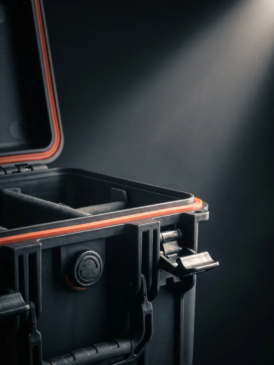
Seal reliability depends on the gasket rather than shell stiffness. Silicone gaskets stay elastic from minus 40 to plus 200 degrees Celsius and are the first choice outdoors. EPDM weathers well but stiffens in cold, and nitrile resists oil but weathers only moderately. Groove compression should sit between 20 and 30 percent: too little leaks, too much accelerates permanent set. Incoming inspection can use pressure decay or immersion sampling; see Airtight Leak Testing for methods.
Cushioning Liners and Compartment Design
If the shell carries external load, the liner carries the last ten centimeters of survival margin. The core of liner design is converting the maximum acceleration the equipment tolerates into a combination of foam thickness and density. The relationship can be simplified as required thickness roughly equal to drop height divided by the cushioning stroke derived from the allowable deceleration.
Three foam families dominate engineering practice, with clearly different characteristics:
| Foam | Density (kg/m3) | Rebound | Behavior After Repeated Shock | Secondary Processing | Typical Location |
|---|---|---|---|---|---|
| --- | --- | --- | --- | --- | --- |
| EPE pearl foam | 20-35 | High rebound | Fast attenuation | Easy hot-cutting and bonding | Large-part wrap, cushion layer |
| EVA | 40-90 | Medium rebound, firmer | Stable | Die-cuttable, thermoformable | Molded liner, module locating |
| IXPE | 30-60 | Low rebound, high energy absorption | Extremely stable | Laminatable, bondable | Precision equipment, repeated transit |
For relay protection modules that are sensitive to mid and high frequency vibration, a three-layer composite is recommended: IXPE as the energy-absorbing base, EVA thermoformed for locating, and EPE as gap filling and leveling. Compartment design should follow one part per cavity with independent cavities, avoiding shared chambers where units collide. Cavity walls should be at least 15 mm thick, and transitions between floor and wall should be radiused to avoid stress concentration and tearing.
One frequently missed issue is foam moisture uptake. EPE and EVA are closed-cell and absorb little, but open-cell foam or flocked fabric liners become moisture reservoirs in prolonged humid exposure. On humid routes the liner should therefore be faced with a PE barrier film.
Latches, Hinges and Pressure Equalization Valves
The three moving parts of a case, namely latches, hinges and the pressure equalization valve, determine whether the protection is actually available. Even a perfect seal means nothing if a latch releases itself under vibration.
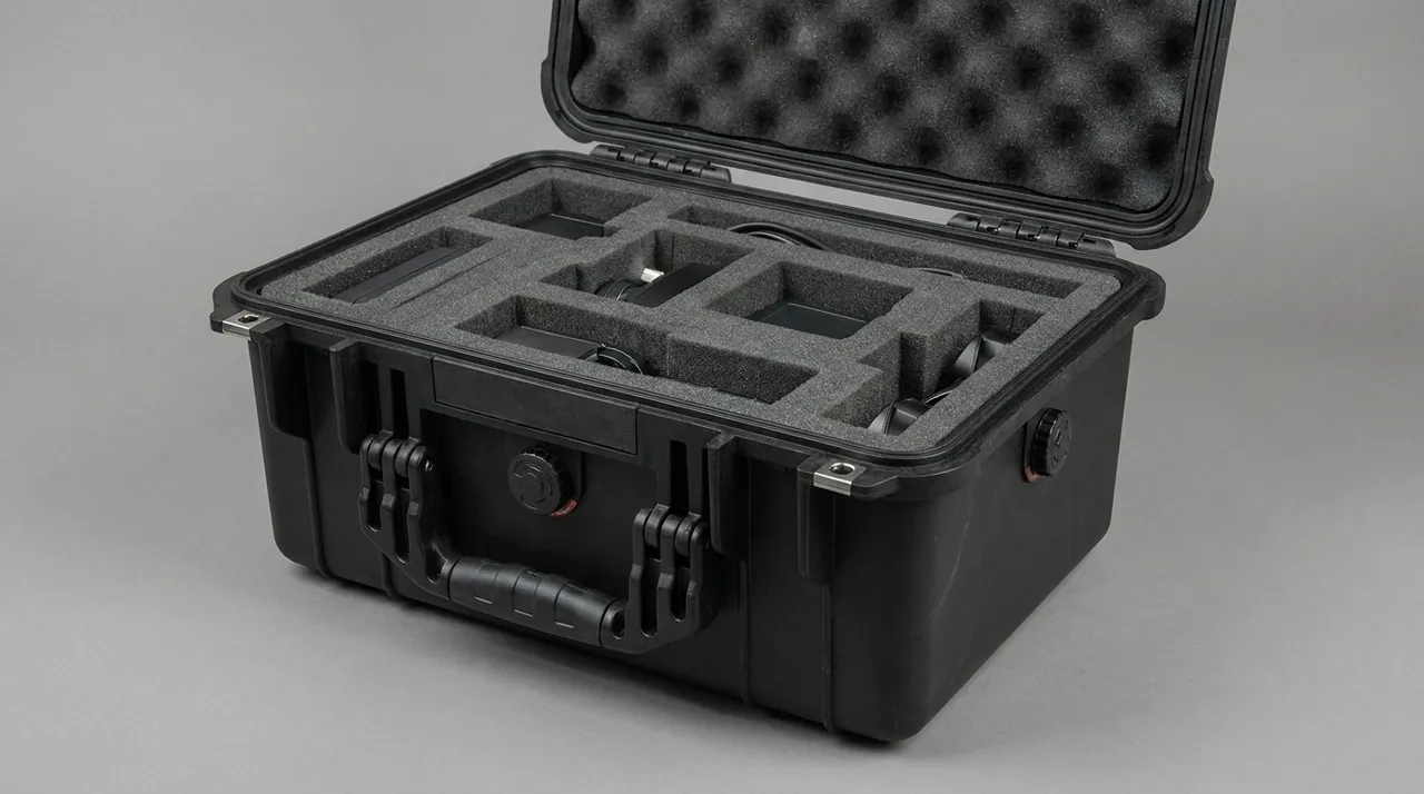
For latches, secondary-equipment cases should use draw latches with a self-locking anti-release feature, and critical models should add spring preload so the lid always presses the gasket with constant force. Latch count should scale with edge length: two per side is enough below 600 mm, three per side is advised from 600 to 1000 mm, and four or more per side above 1000 mm, supported by a cycle life test that typically requires 5,000 open-close cycles without failure.
For hinges, all-metal types beat plastic, but the pin material and lubrication matter: a stainless steel pin with a nylon bushing balances corrosion resistance and low friction, preventing a rusted lid from becoming impossible to open. Heavier cases should use removable hinges so the lid can be taken off on site.
The pressure equalization valve is the breathing valve of a sealed case. When altitude changes, as on a shipment from lowland to plateau, or when temperature swings, the pressure differential can exceed 20 kPa, enough to suck the gasket out of shape or force the lid open. A waterproof breathable valve balances that differential without changing the IP rating and is essential for high-altitude and long-haul routes. Valve airflow and cracking pressure must be matched to case volume; see Pressure Equalization Valve Guide for selection detail.
Stacking Load and Transport Test Verification
Stacking load and transport testing are where every earlier design assumption gets falsified. Stacking load has two distinct cases: long-term static storage and dynamic load in transit. Static stacking should be checked against a one-year storage period with a top load of 300-500 kg, and if lid deflection exceeds 1/200 of the span, load beams must be added. Dynamic load must be checked against the actual number of tiers loaded onto the vehicle.
On the test side, the available procedures and their purposes are summarized below. Note that these are laboratory simulations, not direct field-life predictions, so testing should be treated as a ranking tool between competing designs.
| Test Item | Common Method | Simulated Scenario | Meaning for Secondary Equipment |
|---|---|---|---|
| --- | --- | --- | --- |
| Random vibration | ISTA 3E / ASTM D4169 | Long-haul road transport | Verifies module and terminal fatigue resistance |
| Shock and drop | ISTA 1A / GB/T 4857.5 | Handling drops, sorting impacts | Verifies corner and liner energy absorption |
| Static stacking | GB/T 4857.3 | Multi-tier warehouse storage | Verifies long-term load capacity without collapse |
| Low pressure | ASTM D4169 DC13 | High altitude, air freight | Verifies seal and valve matching |
| Rain and immersion | IEC 60529 | Rainy transport, open storage | Verifies the actual IP rating achieved |
The value of a test report is converting "we believe the protection is good" into "we verified it by a stated method." The full testing path is described in ISTA Transport Testing Procedure.
Temperature, Humidity, Condensation and Salt Spray Control
The three environmental enemies of secondary equipment are heat, moisture and salt spray. High temperature shortens electrolytic capacitor life on a rough rule of halving for every 10 degrees Celsius rise. Humidity lowers insulation resistance and drives metal corrosion. Salt spray mainly attacks terminal plating and fasteners. Coastal substations and sea-export routes must address all three together.
Control works in three layers. The first is structural: avoid enclosed dead spaces inside the case and leave vent channels in the liner so moisture is absorbed by desiccant instead of pooling in a cavity. The second is adsorptive: size silica gel desiccant to case volume and transport duration, with a working estimate of about 20 g per cubic meter, doubled for sea or tropical routes, plus a humidity indicator card. The third is surface-based: metal parts receive zinc plating with passivation or a zinc-flake coating, and fasteners should be 316 stainless steel wherever possible.
Condensation is driven by temperature difference rather than absolute humidity. The case absorbs heat by day and sheds it quickly at night, so once the inner wall drops below the dew point, water condenses. The remedies are reducing the day-night swing through insulation or a light-colored exterior and making the inner wall hydrophilic so droplets do not merge into running streams. For salt spray, neutral salt spray testing can rank schemes, but the mapping from test hours to corrosion grade must be understood properly; see Salt Spray Corrosion Testing.
Commissioning, Calibration and Unpacking Acceptance
Unpacking on arrival is the final link in the protection chain and the one most often done carelessly. A fixed sequence is recommended: check the outer case condition first, then read the humidity indicator card, then open and inspect internal restraint, and only then allow power-up verification. The point of the order is that problems found before power-up make responsibility and resolution far clearer.
Acceptance criteria fall into three groups.
- Appearance: no cracks or through-wall deformation in the case, no twisted or age-cracked gasket, smooth latch and hinge operation.
- Environment: humidity indicator below threshold, no visible water marks, no white or red rust on metal parts.
- Function: normal module insertion force, tight terminals, test links matching the factory state, and intact transformer secondary shorting.
On calibration, transformer ratio and polarity should be rechecked after transport, especially for batches that experienced severe vibration, and protection sampling accuracy should be verified after a warm-up stabilization period so that cold-start deviation is not misread as transport damage. All unpacking records, photographs and calibration data should be archived as input for improving the next packaging batch.
Customization, Tooling and OEM/ODM Services
A standard generic case rarely satisfies module dimensions, transformer weight and lifting method at the same time, so secondary-equipment protection almost always starts with a custom liner and only moves to tooling once volume justifies it. A typical path is: confirm the equipment list and three-view drawings, produce a liner 3D concept with cavity layout, build samples and run initial drop and vibration screening, then move to volume production.
Whether a shell mold is warranted depends on annual volume and structural differentiation rather than on a single order size. Below 500 units per year the combination of a standard shell with a custom liner is usually the right call, since it ships fast and carries low risk. Above 2,000 units per year with stable dimensions, a dedicated mold significantly reduces unit cost and improves consistency.
On the OEM/ODM side, common commissions include brand silk-screen or laser marking, nameplates and accompanying documents such as packing lists, certificates of conformity, humidity indicator cards and desiccant replacement instructions, printed equipment numbers and storage position maps on the liner, and case color matched to a customer swatch. For projects delivered together with the panel, a QR asset label on the outside enables one-code-per-case traceability.
Frequently Asked Questions FAQ
Q: Why not simply use a wooden crate with foam for relay protection equipment?
A: Wooden crates are adequate for short routes and low-value goods, but for relay protection equipment they have four hard limitations. First, timber absorbs moisture and becomes a water source in the rainy season or in sea freight, which actually worsens condensation inside the panel. Second, a crate cannot be reused, and since secondary equipment is transferred frequently, the labor and material cost of re-nailing a crate every time is high, while opening it releases wood dust that contaminates modules. Third, the crate is rigid without being cushioning, so almost all drop energy passes straight into the equipment, which is unfriendly to module solder joints and relay coils. Fourth, a crate cannot deliver a stable IP seal and has no provision for desiccant management or humidity indication. A protective case turns sealing, cushioning, reuse and asset traceability into one reusable system, so its lifetime cost is not higher than timber. It also fits the returnable loop that utilities and EPC contractors increasingly require in their procurement terms.
Q: Should a protection panel be shipped upright or laid flat, and how does the case enforce this?
A: Upright should be the only permitted attitude, because panel modules are cantilever-mounted on guide rails; when the panel lies flat, module weight rests entirely on the rails and sockets, and a long journey deforms rails and sockets. The case enforces upright transport in three ways. Vertical retaining bars inside the case constrain the panel front, back, left and right. The case floor uses load beams and the center-of-gravity line is projected inside the beam footprint to prevent tipping. A resilient pad on the inside of the lid applies light pressure to the panel top once latched, suppressing vertical movement. The case exterior should also mark the center of gravity and lifting points, because on site the panel must be lifted with a sling passed under the base; pulling with a rope on one side very easily causes tilt and internal displacement. A further advantage of a molded retaining geometry is that it stays identical on every trip, so restraint quality no longer depends on how carefully an individual loader stacks the load onto the vehicle.
Q: Why must current transformer secondary terminals be shorted before transport, and how does the case support this?
A: In service a current transformer operates with its secondary nearly short-circuited. If the secondary circuit opens, the entire primary current is used for excitation and the secondary induces thousands of volts, which can both puncture insulation and endanger personnel. Whether at the factory, in storage or during on-site handling, the secondary terminals must therefore be confirmed reliably shorted. The case supports this by reserving a clearance pocket at the transformer terminal box so the shorting bar or link is never crushed by the lid. A locating channel under the transformer prevents the body from rolling, and a shorting status check card inside the case requires confirmation at both unpacking and repacking. For batches stored long term, the shorting terminals should additionally receive anti-oxidation grease so that oxidation cannot defeat the short. Where a batch is stored for more than six months, the transformer should also be checked periodically for insulation resistance and for any oil seepage at the flange, because a shorted secondary protects the winding but does nothing about a slowly leaking gasket.
Q: Is IP67 sealing and internal desiccant an either-or choice?
A: They complement each other and cannot substitute for each other. IP67 addresses liquid water and dust, but its barrier to water vapor is limited, so residual moisture and temperature cycling still cause condensation inside. Desiccant addresses water vapor already inside the case but cannot stop rain from entering directly. The correct approach is to use the seal to keep liquid water outside first, then use desiccant to absorb the initial moisture content plus the small amount permeating during transport, while a humidity indicator card monitors status. Sealing without desiccant still leaves condensation risk on long routes and in hot humid conditions. Desiccant without a working seal saturates within days and then masks the underlying problem. Both together form a complete moisture control system. It is also worth noting that sealing and desiccant work on different timescales: the gasket acts continuously against liquid water, while desiccant capacity is finite and is consumed over the journey, so any route longer than about thirty days usually needs either a larger desiccant charge or an interim inspection.
Q: How should ESD liner material be chosen, and is higher conductivity always better?
A: No, higher conductivity is not better. ESD materials are classified by surface resistivity into conductive, dissipative and insulative types, and plug-in equipment should use the dissipative type, typically 10^6 to 10^9 ohm. The reason is that a conductive material touching module pins or a circuit board directly can produce an instantaneous high-current discharge during live insertion or when a potential difference exists, destroying exactly the components the design intends to protect. A dissipative material instead bleeds charge slowly through a high-resistance path and never produces a damaging discharge current. The recommended structure is a dissipative EVA or modified PP tray, a ground stud inside the case wired to the tray, and metallized shielding bags for outer packaging. Operators should also wear ESD wrist straps and gloves, because the human body is usually the dominant static source. For high-value panel batches, some utilities now specify an ESD audit as part of incoming inspection, measuring surface resistivity on the liner and verifying the grounding path, since latent damage cannot be exposed by ordinary functional testing at the receiving dock.
Q: Which transport tests should a protective case undergo, and what counts as passing?
A: Test items should map to the actual logistics route rather than aiming for a long checklist. Where long road haulage dominates, prioritize random vibration and drop shock, using ISTA 3E or ASTM D4169 for vibration and the ISTA 1A weight-to-height table for drop. Where sea freight and multi-stage transshipment are involved, add static stacking and low pressure. Where open-air storage occurs, rain or immersion verification of the IP rating is mandatory. Passing does not mean the case survived; it means the equipment's functional parameters stayed consistent before and after testing, including module insertion force, terminal contact resistance, transformer insulation resistance and protection sampling accuracy. Pre-test and post-test photographs and data should be retained in the batch quality file. Laboratory testing ranks schemes and cannot be converted directly into field service years. A practical rule is to write the test protocol into the purchase specification together with the acceptance criteria, so that both the case supplier and the receiving inspection team work from the same measurements rather than from a verbal description of the route.
Q: For small-volume purchasing, how should a buyer choose between a custom liner and a mold?
A: The decision rests mainly on annual volume and structural stability, not on the size of a single order. Below roughly 500 units per year, or where the equipment model may change within a year, the standard shell with a custom liner is preferable: the liner can be die-cut or thermoformed into samples quickly, lead time is short, mold investment is low, and a model change only requires a new liner. Where annual volume consistently exceeds 2,000 units and dimensions and cavity layout have stabilized, a dedicated shell mold pays back better, reducing unit cost, improving dimensional consistency and seal stability, and enabling automated fixtures later. A middle path is to tool the liner first while reusing a standard shell, then decide on a shell mold once volume is confirmed, which minimizes early risk. It also helps to freeze the equipment interface drawing before tooling begins, since a late change to connector positions or cable exit direction can invalidate the cavity layout and force a partially re-cut liner.
Q: How long can a protective case be reused, and when should it be retired?
A: Service life is governed by seals and structural parts rather than appearance. An engineering plastic case is typically designed for about five to eight years under normal use, but the real determinants are three conditions: whether the gasket still has elasticity, recovering after compression without permanent set; whether latches still hold closing force, checkable with a feeler gauge on the lid-to-shell gap; and whether the shell has through cracks or creep-induced deformation. Any single failed condition calls for replacing that component rather than scrapping the whole case. A visual and seal inspection every six months and an unpacking record after every shipment are good practice, and coastal or high-UV environments warrant shorter intervals. Recording the date each case enters service also lets a fleet manager retire units by batch rather than by surprise failure in the field. Retired cases should be sorted by material for recycling, separating engineering plastics from metal parts.
Conclusion and Related Reading
Relay protection transport defends against failure that stays invisible on arrival. Building anti-vibration, moisture, ESD and contact defenses into one reusable, traceable case system is worth more than any repair afterward. JUNZHIJIA supports that goal end to end.
Related Reading